Hugo Müller TS 30.00 mod User manual

Hugo Müller GmbH & Co KG, Karlstraße 90, DE-78054 VS-Schwenningen
TS 30.00 mod / pro
GS 30.00 mod / pro
GS 40.00 mod / pro
Allgemeine technische Daten
Bedienungsanleitung
BA TS3000 GS3000 GS4000 mod-pro Hardware HM; de, en -23876- 2022.08V02
de
Vor Montage- und Installationsarbeiten Spannung
freischalten und Spannungsfreiheit prüfen!
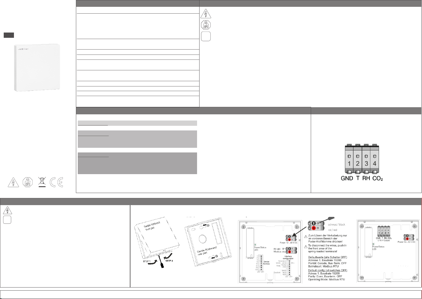
Schritt 1:
Schritt 2:
Schritt 3:
Schritt 4:
Beachten Sie unbedingt die weiteren, oben aufgeführten
Sicherheitshinweise!
Montage
!
www.hugo-mueller.de
WARNUNG! ES BESTEHT GEFAHR DURCH EINEN ELEKTRISCHEN SCHLAG ODER BRANDGEFAHR!
!! Einbau, Anschluss und Montage dürfen ausschließlich von einer Elektrofachkraft durchgeführt werden !!
Nur an die auf dem Gerät angegebene Spannung und Frequenz anschließen! [12-40 V DC]
§
§Bei Eingriffen oder Änderungen am Gerät erlischt die Garantie!
§Das Gerät ist so zu installieren, dass auch außergewöhnlich hohe Störstrahlung die Funktion nicht beeinträchtigen kann!
§Installation und Anschluss dürfen nur entsprechend den nationalen Bau- und Elektrovorschriften / Sicherheitsbestimmungen
durchgeführt werden!
§Beschädigte Geräte dürfen nicht in Betrieb bzw. müssen sofort außer Betrieb genommen werden!
§Beachten Sie die Vorschriften und Hinweise aus dem Handbuch „Haus- und Gebäudesystemtechnik" des ZVEI/ZVEH.
Dies gilt insbesondere für die fachgerechte Verlegung der Busleitungen und die Inbetriebnahme des KNX Gerätes.
Das Gerät kann in folgenden Anwendungen eingesetzt werden: Überwachung der Luftgüte in der Gebäudesystemtechnik
§
(Schule, Büro, Hotel, Tagungsstätte etc.), Datenübertragung und Regelung per Bus-System.
Das Gerät ist für den Betrieb gemäß den aufgeführten technischen Daten geeignet.
§
Das Gerät ist nicht geeignet für sicherheitsrelevante Aufgaben, wie z.B. Fluchttüren, Brandschutzeinrichtungen, Gärkeller
§
etc.
Die bestimmungswidrige Verwendung des Gerätes kann zu Sach- und Personenschäden führen
§
Das Gerät ist nicht für eigenmächtige bauliche Veränderungen, Reparaturen und sicherheitsrelevante Aufgaben
§
vorgesehen.
Das Gerät ist nicht für den Einsatz im Außenbereich und in Nasszellen vorgesehen.
§
Das Gerät ist umweltgerecht und entsprechend den Elektrovorschriften zu entsorgen.
§
!
Öffnen Sie das Gehäuse an der Unterseite durch Eindrücken
der Lasche mittels Schraubendreher und nehmen das
Geräte-Vorderteil ab.
Verschrauben Sie die Geräte-Rückwand mit einer
Unterputzdose bzw. direkt auf die Wand.
Gerät mit der RS485 Schnittstelle verbinden und gemäß der
vor Ort notwendigen Parameter konfigurieren.
Spannungsversorgung anschließen.
Setzen Sie das Geräte-Vorderteil wieder auf.
Das Gerät ist für die Montage auf einer Unterputzdose oder für die
§
Wandmontage geeignet.
Bitte achten Sie darauf, dass kein Staub in das Gerät gelangt.
§
Nach Inbetriebnahme benötigt das Gerät ca. 5 Minuten bis die ersten
§
Sensorwerte zur Verfügung stehen.
Sicherheitshinweise / Bestimmungsgemäße und bestimmungswidrige Verwendung / Entsorgung
Anschlussspannung
Mod-Geräte:
Busstrom
Protokoll / Schnittstelle
Baudraten
Einstellbare Parität
Pro-Geräte:
Analogausgänge
zul. Umgebungstemp.
Gehäuse
Gehäusefarbe
Montage
Anschlussart
Schutzart
Schutzklasse
12-40 V DC
< 20 mA
Modbus ASCII, Modbus RTU / RS 485
4800, 9600, 19200 (default), 38400
Keine, Gerade, Ungerade
3x 0-10V (je nach Ausführung)
0...+50 °C
selbstverlöschendes Thermoplast
Studioweiß (ähnlich RAL 9016)
Tiefschwarz (ähnlich RAL 9005)
Wandmontage Aufputz
(empfohlen: Montage auf Unterputzdose)
Push-in Klemme
IP 20 (DIN EN 60529)
III bei bestimmungsgemäßer Montage
Produktbezogene technische Daten
Sensorik
Co2 (Messbereich: 390...5.000 ppm)
relative Luftfeuchtigkeit (Messbereich: 0...100 %)
Temperatur (Messbereich: 0...+50 °C)
Luftdruck (Messbereich: 300...1.100 hPa)
GS 30.00 mod/pro relative Luftfeuchtigkeit (Messbereich: 0...100 %)
Temperatur (Messbereich: 0...+50 °C)
Luftdruck (Messbereich: 300...1.100 hPa)
TS 30.00 mod/pro
Temperatur (Messbereich: 0...+50 °C)
Störquellen
Die Messergebnisse des Gerätes können durch äußere
Einflüsse negativ beeinflusst werden, wie z.B.
Zugluft und Luftbewegung: z.B. durch Fenster, Türen,
§
Konvektion, Heizung oder Personen.
Erwärmung oder Abkühlung: z.B. Sonnenbestrahlung oder der
§
Montage an einer Außenwand.
Wärmequellen: In direkter Nähe zu elektrischen Verbrauchern,
§
z.B. Dimmer
Erschütterungen oder Schläge, denen das Gerät ausgesetzt
§
wird oder wurde.
Verschmutzung durch Farbe, Tapetenkleister, Staub, etc.:
§
z.B. bei Renovierungsarbeiten
Organische Lösemittel oder deren Dämpfe
§
z.B. Reinigungsmittel
Weichmacher aus Aufklebern und Verpackungen:
§
z.B. Luftpolsterfolie oder Styropor
Schritt 1: Schritt 2: Mod - Geräte Pro - Geräte
GS 40.00 mod/pro
Steuerausgang Messwertausgabe
Temperatur 0 - 50 °C (0 - 10 Volt)
Relative Luftfeuchtigkeit 0 - 100% rH (0 - 10 Volt)
Kohlenstoffdioxid CO2 0 - 2000 ppm (0 - 10 Volt)
Pro - Geräte: Analoge Steuerausgänge

Hugo Müller GmbH & Co KG, Karlstraße 90, DE-78054 VS-Schwenningen
TS 30.00 mod / pro
GS 30.00 mod / pro
GS 40.00 mod / pro
General technical data
Instruction manual
BA TS3000 GS3000 GS4000 mod-pro Hardware HM; de, en -23876- 2022.08V02
en
Disconnect device from power supply for wiring and
installation purposes! Check power supply is disconnected!
Step 1:
Step 2:
Step 3:
Step 4:
Attention! You have to check and consider the
safety instructions above!
Montage
!
www.hugo-mueller.de/en/
CAUTION! DANGER OF FIRE AND ELECTRIC SHOCK!
!! Installation and assembly of electrical equipment must be carried out only by a skilled person !!
Connect only to suitable supply voltage [KNX bus voltage (nominal voltage 29V)].
§
§Warranty void if housing opened by unauthorized person!
§The electronic circuit is protected against a wide range of external influences. Incorrect operating may occur if external in
fluences exceed certain limits!
§Installation and assembly of electrical equipment must be in accordance with national building, electrical and safety codes!
§Defective devices / sensors have to be put out of service immediately!
§Observe the regulations and instructions in the ZVEI/ZVEH handbook (building system technology). Especially the
professional installation of the bus lines and the professional installation and start-up of KNX devices must be observed!
The device can be used in following applications: monitoring of the air quality in building systems technology
§
(schools, offices, hotels, conference venue etc.), data transfer and regulation via bus system.
The device is intended for use in accordance with the defined technical data.
§
The device is not qualified for security relevant tasks such as emergency doors, fire protection equipment, fermenting
§
cellars etc.
The inappropriate use of the device can cause damage to property and persons.
§
The device is not intended for use of unauthorized constructional alterations, repairs and security relevant tasks
§
The device is not intended for use in outdoor areas and wet rooms
§
The device has to be disposed in an environmentally friendly manner according to the current electrical codes!
§
!
Open the device with a small screw driver by pushing in the
lever at the bottom of the housing and gently remove the
front part.
Fix the rear part, either directly to the wall or on a
flush-mounting box.
Connect the device to the RS485 interface and configure it
according to the configure according to the parameters required
on site. Connect the power supply.
Reattach the front part.
This device is suitable for wall mounting or for mounting on a
§
flush-mounting box.
Ensure that no dust gets inside the device.
§
After initial startup, the device requires up to 5 minutes until the sensor
§
sends the first values.
Safety instructions / Intended use and inappropriate use / Disposal
Power supply
Mod - Devices:
Bus current
Protocol / Interface
Baud rates
Parity settings available
Pro - Devices:
Analogue outputs
permitted ambient
temperature
Housing
Housing colour
Mounting
Type of connection
Type of protection
Class of protection
12-40 V DC
< 20 mA
Modbus ASCII, Modbus RTU / RS 485
4800, 9600, 19200 (default), 38400
None, even, odd
3x 0-10V (depend on model)
0...+50 °C
self-extinguishing thermoplastic
studio white (similar to RAL 9016)
jet black (similar to RAL 9005)
wall mounting
(preferrably combined with flush-mounting box)
push-in connector
IP 20 (DIN EN 60529)
III when installed according to regulations
Product specific technical data
Sensors
Co2 (Measuring range: 390...5.000 ppm)
Relative humidity (Measuring range: 0...100 %)
Temperature (Measuring range: 0...+50 °C)
Atmospheric pressure (Measuring range: 300...1.100 hPa)
GS 30.00 mod/pro Relative humidity (Measuring range: 0...100 %)
Temperature (Measuring range: 0...+50 °C)
Atmospheric pressure (Measuring range: 300...1.100 hPa)
TS 30.00 mod/pro
Temperature (Measuring range: 0...+50 °C)
Source of interference
The sensor values of the device can be negatively influenced by
external impacts as e.g.:
Draught and air movement: e.g. through windows, doors,
§
convection, heating and people
Warming and cooling:
§
e.g. sunlight or mounting on an outside wall
Heat sources: close to installed electrical consumers
§
e.g. dimmers
Vibrations or shocks, which the unites are or were subjected to
§
Pollution due to colors, wallpaper paste, dust
§
e.g. at renovation work
Organic solvents or their vapours: e.g. detergents
§
Plasticizers from stickers and packaging
§
e.g. bubble wrap or polystyrene
Step 1: Step 2: Mod - Devices Pro - Devices
GS 40.00 mod/pro
Output Measurement output
Temperature 0 - 50 °C (0 - 10 Volt)
Relative humidity 0 - 100% rH (0 - 10 Volt)
Carbon dioxide CO2 0 - 2000 ppm (0 - 10 Volt)
Pro - Devices: Analogue Outputs
This manual suits for next models
5
Table of contents
Languages:
Other Hugo Müller Accessories manuals