Humphree HCS-5 User guide

SETUP MANUAL
FIN AND INTERCEPTOR
HCS-5
HCS-5
For software versions 5.7.x

SAFETY INFORMATION . . . . . . . . . . . . . . . . . . . . . . . 3
General . . . . . . . . . . . . . . . . . . . . . . . . . . . . 3
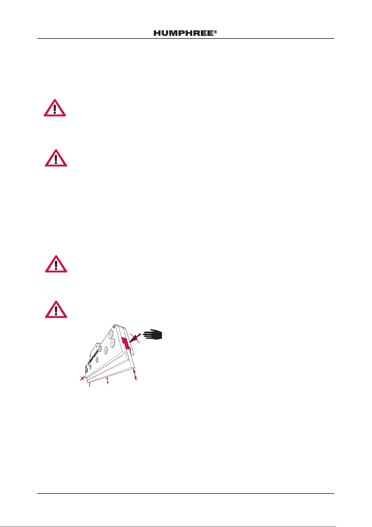
Interceptor Safety Information . . . . . . . . . . . . . . . . . . . . 3
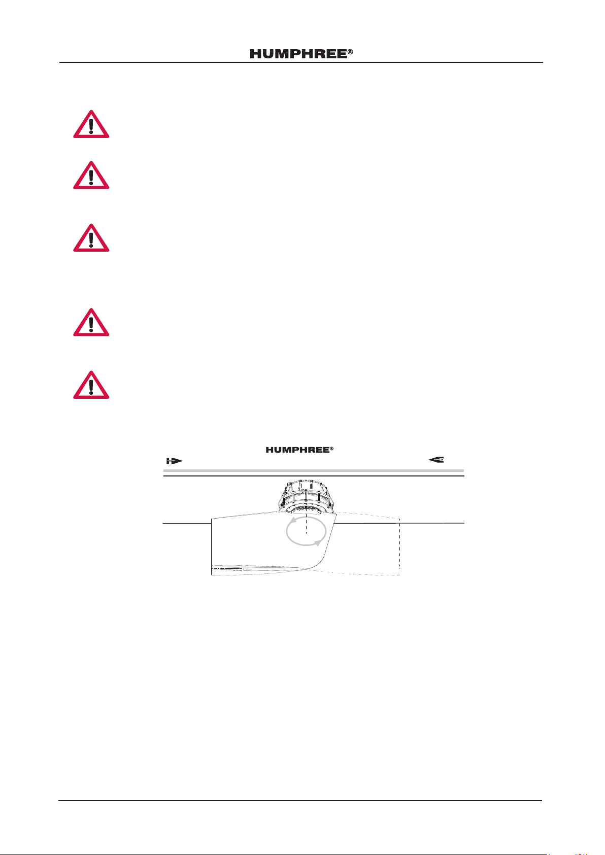
Fin Safety Information . . . . . . . . . . . . . . . . . . . . . . . 4
IMPORTANT NOTICES . . . . . . . . . . . . . . . . . . . . . . . 5
FUNCTIONS OVERVIEW . . . . . . . . . . . . . . . . . . . . . . 6
REQUIRED SETUP . . . . . . . . . . . . . . . . . . . . . . . . . 7
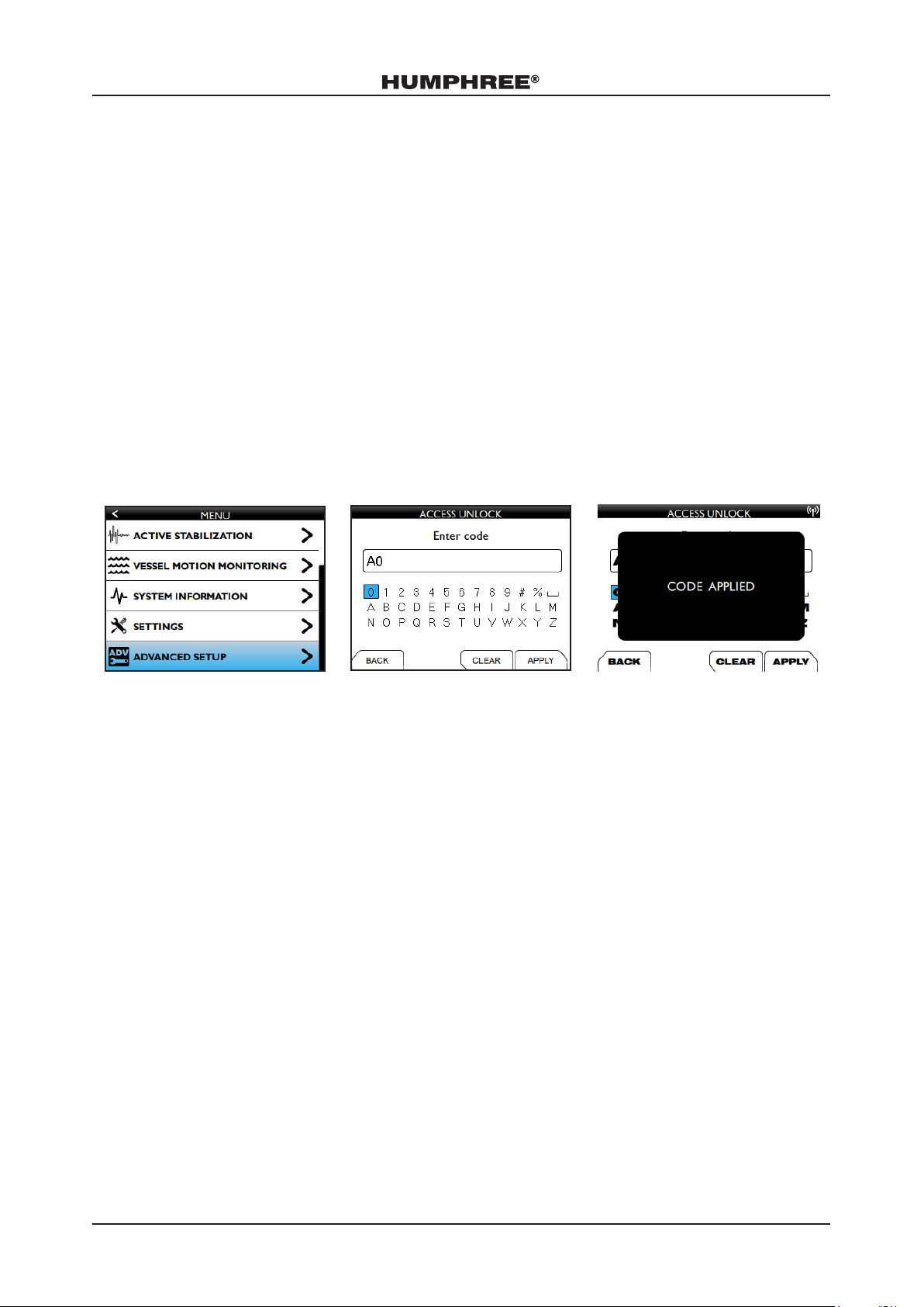
1.Access to Advanced Setup. . . . . . . . . . . . . . . . . . . . . 7
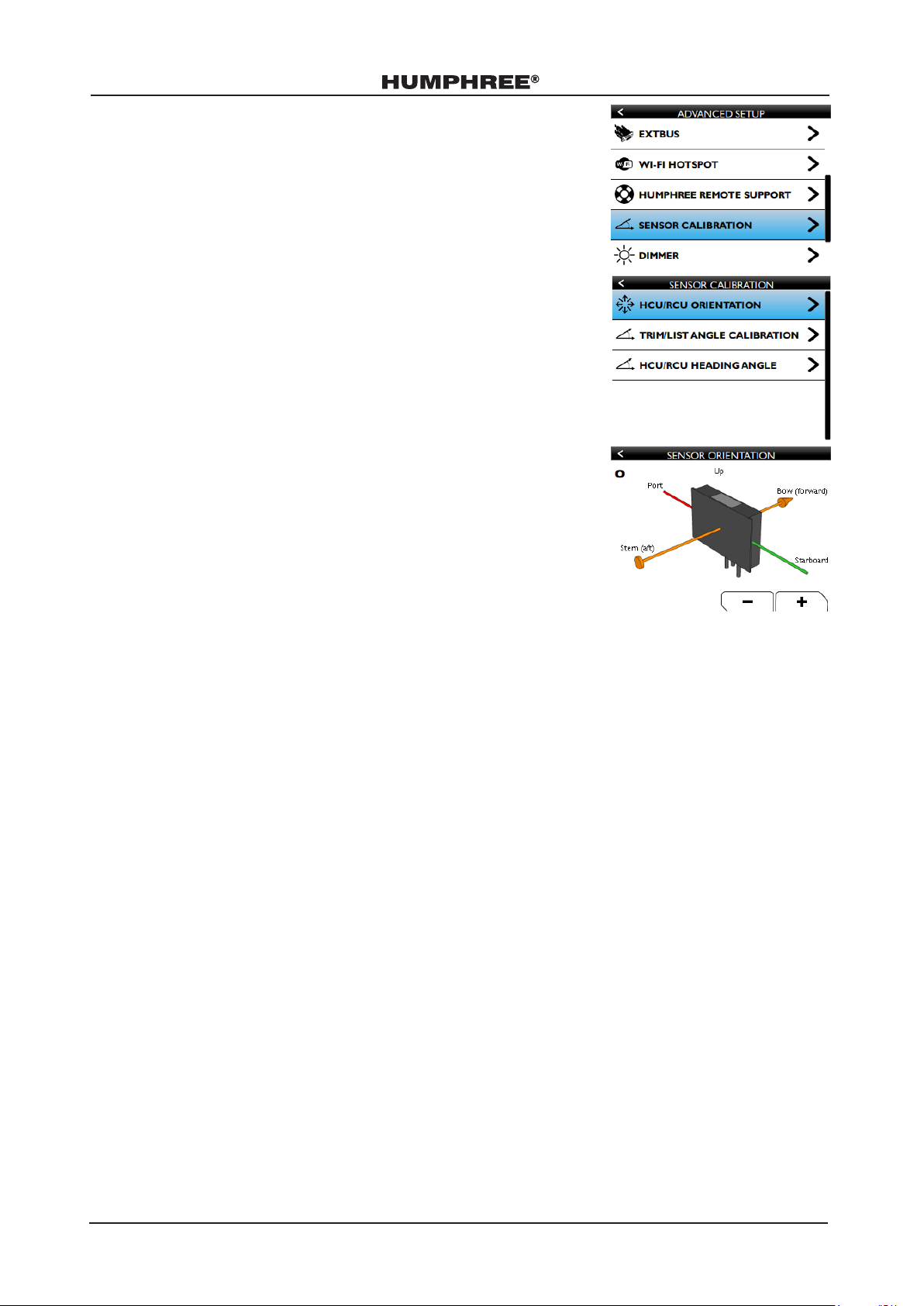
2. RCU Orientation . . . . . . . . . . . . . . . . . . . . . . . . 8
3.Trim/List Angle Calibration . . . . . . . . . . . . . . . . . . . . 9
4. GPS Selection . . . . . . . . . . . . . . . . . . . . . . . . . 9
5. Interceptor Calibration . . . . . . . . . . . . . . . . . . . . . . 11
6.Align Fins and Set Fin Zero Positions. . . . . . . . . . . . . . . . . 12
RUDDER INPUT SIGNAL . . . . . . . . . . . . . . . . . . . . . . 17
Install Rudder Input Sources . . . . . . . . . . . . . . . . . . . . . 17
Calibrate the Rudder Input Signal . . . . . . . . . . . . . . . . . . . 21
AUTOMATIC TRIM CONTROL . . . . . . . . . . . . . . . . . . . . 23
AUTOMATIC LIST CONTROL . . . . . . . . . . . . . . . . . . . . 25
Advanced Settings . . . . . . . . . . . . . . . . . . . . . . . . 26
COORDINATED TURN . . . . . . . . . . . . . . . . . . . . . . . 28
STABILIZATION . . . . . . . . . . . . . . . . . . . . . . . . . . 31
INTERCEPTOR STEERING . . . . . . . . . . . . . . . . . . . . . . 32
VESSEL MOTION MONITORING . . . . . . . . . . . . . . . . . . . 36
ADVANCED SETUP MENU . . . . . . . . . . . . . . . . . . . . . . 38
Alarm History . . . . . . . . . . . . . . . . . . . . . . . . . . 38
EXTBUS . . . . . . . . . . . . . . . . . . . . . . . . . . . . 38
Wi-Fi Hotspot . . . . . . . . . . . . . . . . . . . . . . . . . . 38
Humphree Remote Support . . . . . . . . . . . . . . . . . . . . 39
Sensor Calibration . . . . . . . . . . . . . . . . . . . . . . . . 39
Fin Settings . . . . . . . . . . . . . . . . . . . . . . . . . . . 40
Dimmer . . . . . . . . . . . . . . . . . . . . . . . . . . . . 40
Measurement . . . . . . . . . . . . . . . . . . . . . . . . . . 42
Simulation. . . . . . . . . . . . . . . . . . . . . . . . . . . . 45
Contents

3
SETUP MANUAL HCS-5 020312 5.7.x 02
SAFETY INFORMATION
General
Please read the manual carefully before operating the Humphree system and pay extra attention to the following
safety notices:
WARNING!
●Make sure to read all Warnings thoroughly as they contain important safety information.The Humphree
system can cause serious injuries or death if not used properly.
IMPORTANT!
●The Important notices contain important instructions to avoid damage or malfunctions on the Humphree
system or other property.
NOTE!
●A note contains information that facilitates the work when operating the Humphree system.
Interceptor Safety Information
WARNING!
When installing the interceptors, make sure that there is no electrical current connected to them.
Isolate shore electrical current to the engine block, battery charger, or accessories mounted on the
engine.
WARNING!
Sharp edges, watch your fingers.

4
SETUP MANUAL HCS-5 020312 5.7.x 02
Fin Safety Information
WARNING!
Before docking, make sure the Humphree system is turned off by the main switch.
WARNING!
Before installation or service, the electrical power to the servo units with dedicated power supply must
be switched off.
WARNING!
Fins must be in neutral position before the boat is lifted out of the water.The lifting device and/or
struts must be placed in such a way that the fins are not damaged.To create a safe workplace in the
area around the ns, it is recommended to have an enclosed area of at least 1.5 x n length 360°
around the n.
WARNING!
There is a risk of being squeezed between the fin and the hull when working in the area of the fin.
Work with caution in the area around the fins.
WARNING!
The fins are rotating when enabled in ZERO SPEED STABILIZATION mode. Swimmers must stay away
from the fins due to the risk of injury. For safety around the vessel, make sure the installer has applied
appropriate warning signs prominently on the hull above the waterline above each fin.
NO SLINGS NO SWIMMING

5
SETUP MANUAL HCS-5 020312 5.7.x 02
IMPORTANT NOTICES
●The following manual is provided for Humphree service workshops, ship-builders, machine manufacturers,
and other authorized workshops that have personnel with qualied professional training. The installation
instructions are only for professionals. If the installation instructions are not followed or if the work is carried
out by non-professional personnel, Humphree will not assume any liability for damage that may incur to
materials or personal injury.
●The information in this document is the property of Humphree and may not be copied or communicated to
a third party, or used for any purpose other than that for which it is supplied, without the express written
consent of Humphree.This information is given in good faith based upon the latest information available to
Humphree, no warranty or representation is given concerning such information, which must not be taken
as establishing any contractual or other commitment binding upon Humphree or any of it subsidiary or
associated companies.
●If the manual is lost or worn, see www.humphree.com or contact your local Humphree dealer.
●The contents of the manual and equipment specications are subject to change without notice.
●All illustrations in the manual are schematically correct but may not be exact copies of the corresponding
equipment on your vessel.
●The screens shown in the manual may not match in detail the screens you see on the display.The screens you
see depends on software versions, system conguration and system settings.
●Humphree will assume no responsibility for damage caused by improper use or modication of the
interceptor system parts, or claims of loss of prot by a third party.
●The interceptor system is protected by patent.
●Inspect the parts at arrival for damage occurred during transportation.

6
SETUP MANUAL HCS-5 020312 5.7.x 02
FUNCTIONS OVERVIEW
The following table lists all the available Humphree functions and the required features that must be set up before
using the functions.
HUMPHREE FUNCTION REQUIRED SETUP
AUTO TRIM ●RCU Orientation
●Trim/List Angle
●GPS
AUTO LIST ●RCU Orientation
●Trim/List Angle
●GPS
COORDINATED TURN ●RCU Orientation
●Trim/List Angle
●GPS
●Rudder Input Signal
ACTIVE STABILIZATION ●RCU Orientation
●Trim/List Angle
●GPS
INTERCEPTOR STEERING ●RCU Orientation
●Trim/List Angle
●GPS
●Rudder Input Signal
●Handshaking Signals
ZERO SPEED STABILIZATION ●RCU Orientation
●Trim/List Angle
●GPS
FISH HUNTING MODE ●RCU Orientation
●Trim/List Angle
●GPS
VESSEL MOTION MONITORING ●RCU Orientation
●Trim/List Angle
●GPS
●Red and Yellow Impact Levels

7
SETUP MANUAL HCS-5 020312 5.7.x 02
REQUIRED SETUP
The following are required steps that must be done before using any of the Humphree functions:
1. Access to Advanced Setup
2. RCU Orientation
3. Trim/List Angle Calibration
4. GPS Selection
5. Interceptor Calibration
6. Align Fins and Set Fin Zero Position
1.Access to Advanced Setup
To be able to access some of the required setup for the Humphree functions, the user must rst get access to the
ADVANCED SETUP.
7. Enter the main menu and navigate to ADVANCED SETUP.
8. Enter A0.
9. Press APPLY to proceed.

8
SETUP MANUAL HCS-5 020312 5.7.x 02
2. RCU Orientation
NOTE!
Incorrect RCU orientation will lead to sensor malfunctions in the Humphree
system.
It is always RCU-1 that must correspond to the RCU orientation in the control
panel.The default orientation is 0 but the RCU-1 can also be installed in a
different orientation than default.
The following steps must be performed before using any of the Humphree
functions:
1. Find the location of the RCU-1 in the vessel. Make sure its in eyesight when
doing the following setup.
2. Go to MENU/ADVANCED SETUP.
3. Navigate to SENSOR CALIBRATION.
4. Select RCU ORIENTATION.
5. Adjust the image on the screen and make sure it corresponds to the physical
RCU-1 that is installed in the vessel.
6. Wait two minutes before proceeding with the required setup.

9
SETUP MANUAL HCS-5 020312 5.7.x 02
3.Trim/List Angle Calibration
NOTE!
Incorrect calibration of trim/list angles will lead to malfunctions in the
Humphree system.
Make sure the vessel is at dock at zero speed and has 0° list before proceeding
with the steps.
1. Load the vessel so that the vessel is on an even keel.
2. Navigate to ADVANCED SETUP/SENSOR CALIBRATION.
3. Select TRIM/LIST ANGLE CALIBRATION.
4. Press RESET for the TRIM and LIST angles to be set to 0.
5. The TRIM and LIST angles can also be ne tuned using the PLUS or MINUS
function keys.
4. GPS Selection
There are several ways to setup a GPS that corresponds with the Humphree Control System (HCS).
●Humphree GPS
●NMEA 2000
●EXTBUS
HUMPHREE GPS
The Humphree GPS will function as soon as it is installed by cable.
Instructions on how to install the Humphree GPS cable can be found in the Installation
Manual.
NMEA 2000
With NMEA 2000, selections of available sources for boat speed, are made.
Settings for NMEA 2000 can be found in MENU/SETTINGS/NMEA 2000 SETUP.
AUTOMATIC GPS SELECTION is ticked by default.
The system automatically selects a GPS source.
If the automatic selection has picked a GPS that does not work properly:
1. Note the address of the GPS unit to avoid selecting the same in the manual
procedure.
2. Untick the AUTOMATIC GPS SELECTION box.
3. Enter MANUAL GPS SELECTION.
4. The system will search for available GPS units and present a list.
5. Select GPS unit.
6. If no GPS units are found, check the electrical connections.

10
SETUP MANUAL HCS-5 020312 5.7.x 02
WATER SPEED
Tick the USE WATER SPEED box to use water speed as primary speed source,
with fallback to the GPS signal if the water speed sensor drops out.
As a default, the HCS-5 uses GPS as the primary speed source, with fallback to
water speed if the GPS signal drops out and a water speed sensor is available.
EXTBUS
If the use of other interfaces than the Humphree GPS or NMEA 2000 is required, GPS through EXTBUS is the
solution. See the chapter RUDDER INPUT SIGNAL for further instructions.

11
SETUP MANUAL HCS-5 020312 5.7.x 02
5. Interceptor Calibration
Depending on the system that is installed, the Humphree functions must be calibrated before usage.
IMPORTANT!
The vessel must be at zero speed when performing a calibration.
1. Go to MENU/SETTINGS/INTERCEPTOR CALIBRATION.
2. Tick the ENABLE CALIBRATION OPTION box.
3. CALIBRATE SERVOS will be visible on the screen.
4. Navigate to CALIBRATE SERVOS.
5. Press RUN.
6. Wait for the STATUS to say Calibration OK.
NOTE!
If the calibration fails, the solution can be found in the alarm list.
Go to MENU/SYSTEM INFORMATION/ALARMS.

12
SETUP MANUAL HCS-5 020312 5.7.x 02
6.Align Fins and Set Fin Zero Positions
NOTE!
●The vessel must be on land for the following instructions.
●It is recommended to be 2-3 people to perform the following steps smoothly.
MARK THE FINS
The following steps must be performed on all ns.
1. Mark the trailing edge at a level similar to the image.
2. Measure the distance from the hull to the mark.

13
SETUP MANUAL HCS-5 020312 5.7.x 02
3. Mark the bow of the n at the same height from the hull surface.
Mark at the center of the bow.
4. Measure the distance between the trailing edge at the mark position and the keel center line.
5. Measure the distance between the n bow mark position and the keel center line.

14
SETUP MANUAL HCS-5 020312 5.7.x 02
SET FIN ZERO POSITION
6. Go to MENU/SETTINGS/SERVO CONFIGURATION.
7. Select a servo unit in the list.
8. If there is a servo that the system does not recognize, the SERVO
CONFIGURATION description field will say Servo assignment mismatch.
9. Press ASSIGN SERVO.
NOTE!
As a safety precaution, the system will automatically assign n limits to their
current position.
The serial number for the assigned servo will from now on be logged in the memory of the system.
10. Navigate to SERVO CONFIGURATION and press ON.
11. Go to FIN ZERO POSITION.
12. For this step, it is recommended to have one person at the control panel
and two people that measures.
Always be cautious as the n will rotate.
Use the function buttons to rotate the n clockwise and
counterclockwise until the two distances of the n (bow and trailing edge)
is equal within 0-5mm. Be as precise as possible.

15
SETUP MANUAL HCS-5 020312 5.7.x 02
Press SET ZERO to set the n zero position.
13. The following pop-up will be present.
If the vessel is still on land, press NO.
Press YES to remove the n limits.
NOTE!
Do not remove the fin limits until the vessel is placed in water.
14. Navigate to SERVO CONFIGURATION and press OFF.
NOTE!
Turning off the servo configuration is mandatory.
If the user tries to exit the servo configuration without
turning it off, the following pop-up will be visible.
15. Repeat the steps 1 to 14 for all ns.
16. Once all ns are done, the n zero positions have been set.
NOTE!
The fin zero positions are permanently stored in the memory
of the servo unit and will not be affected by loss of power supply.

16
SETUP MANUAL HCS-5 020312 5.7.x 02
FIN LIMITS
Fin limits are used when the hull of the vessel prevents the n to move freely.
When the vessel is on land, it is recommended to have n limits to prevent the ns from rotating freely.
1. Navigate to SERVO CONFIGURATION and press ON.
2. Enter LIMITS.
3. Go to FIN LIMITS and press ON.
4. Use the CCW function button to rotate the n counter clockwise.
5. Press SET CCW to set the n limit.
6. Use the CW function button to rotate the n clockwise.
7. Press SET CW to set the n limit.
8. Navigate to SERVO CONFIGURATION and press OFF.
NOTE!
Turning off the servo configuration is mandatory.
If the user tries to exit the servo configuration without
turning it off, the following pop-up will be visible.

17
SETUP MANUAL HCS-5 020312 5.7.x 02
RUDDER INPUT SIGNAL
NOTE!
Calibration of rudder input signal is necessary for the following Humphree functions:
●Interceptor Steering
●Coordinated Turn
Install Rudder Input Sources
Table x is an overview of the different rudder input sources.
Electrical
interface
Connection
Position
Signal Calibration
needed
Other
VP1100 Control Panel NMEA 0183 YES
Rudder Angle Sender
(Ampere)
RCU562 4-20mA YES
Rudder Angle Sender
(Volt)
RCU562 0-5V YES
EXTBUS Control Panel
RCU562
RSA YES See Extbus Manual
for signal info.
NMEA 2000 Drop
Cable
Control Panel NMEA 2000 YES
SIMRAD RF25 &
NMR501
RCU NMEA 2000 YES
EXTBUS Control Panel
RCU562
STC NO See Extbus Manual
for signal info.
NMEA 2000
The NMEA 2000 Drop Cable is pre-tted with the standardized NMEA 2000 connector and is compatible with a
NMEA 2000 T-Connector or a Network Hub.The NMEA 2000 Drop Cable is part of the Main Control Panel Kit that
is delivered with all Humphree systems.
Connect the NMEA 2000 Drop Cable to the Control Panel according to the image.

18
SETUP MANUAL HCS-5 020312 5.7.x 02
Volvo Penta Interface
The Volvo Penta Interface (VPI100) is used for reading the rudder position fromVolvo Penta engines. The VPI100 shall
be installed close to the Humphree control panel to avoid long cable extensions. Mount the VPI100 with four M5
bolts or equivalent.
1. Fasten theVPI100 onto a stable bulkhead or equivalent, close to the
control panel.
2. Connect CABLE (A) to the Volvo Penta Multilink HUB or the Volvo
Penta Multilink Breakout Y-split Cable.
3. Connect CABLE (B) using MOLEX to the backside of the CP.
4. Perform a Volvo Penta Auto Conguration. See the Volvo Penta Manuals.
5. Navigate to ADVANCED SETUP/EXTBUS in the HCS.
6. Select EXTBUS ON THIS PANEL.
7. Set BAUDRATE of the bus to 4800.
8. Untick the RS-422 box.
9. Perform the steps in chapter RUDDER INPUT SIGNAL.
CP
VPI100
CABLE (A)
CABLE (B)

19
SETUP MANUAL HCS-5 020312 5.7.x 02
RS-232/RS-422
1. Determine the connection type between HCS-5 and the external system. HCS-5 supports RS-232 and RS-
422.
NOTE!
Only one input source can be connected.
2. Use one of the following to connect RS-232/RS-422 to HCS-5.
a. EXTBUS cable
b. Interface cable from a RCU
NOTE!
The interface cable from a RCU is only compatible with RS-422.
3. Navigate to MENU/ADVANCED SETUP/EXTBUS.
4. Select EXTBUS ON THIS PANEL or EXTBUS ON RCU.
5. Do the steps described under EXTBUS ON THIS PANEL or EXTBUS ON
RCU.
6. Setup the external system and select a signal.The communication standard is
NMEA 0183.
a. Rudder Sensor Angle (RSA)
b. Steering Control Signal (STC)
7. Make sure that the transmitting unit is sending the RSA or STC sentence.
8. If STC is selected, no rudder calibration is needed.
NOTE!
The signals for RSA are described in the EXTBUS Manual.
9. If STC is selected, perform the steps described in chapter RUDDER INPUT SIGNAL..
NOTE!
The signals for STC are described in the EXTBUS Manual.
EXTBUS ONTHIS PANEL
1. Press ON to enable EXTBUS.
2. Set BAUDRATE. Default is 4800 but it is possible to select 4800, 9600,
19200, 38400, 57600, and 115200.
3. RS-232 is the default setting, press ON to select RS-422.
4. Go to NMEA RECEIVE STATUS to make sure that there is NMEA trafc.
5. Setup the external system and select a signal.The communication standard is
NMEA 0183.
a. Rudder Sensor Angle (RSA)
b. Steering Control Signal (STC)

20
SETUP MANUAL HCS-5 020312 5.7.x 02
EXTBUS ON RCU
NOTE!
The RCU is only compatible with RS-422.
6. Press the PLUS or MINUS function keys to select BAUDRATE. Default is 4800 but it is possible to select 4800,
9600, 19200, 38400, 57600, and 115200.
Simrad RF25 and NMR501
1. Mount the NMR501 with four screws onto a stable bulkhead.
2. Use CABLE A to connect NMR501 to the RCU.
a. Remove the termination plug in the RCU and replace it with CABLE A.The NMR501 has a termination
built in.
3. Use CABLE B to connect RF25 to NMR501.
Analog 0-5V or 4-20mA Signal
As a safety precaution to reduce the risk of unwanted Interceptor movements caused by a malfunctioning rudder
position sensor, the Humphree Control System constantly performs a Signal Range Check (SRC) of the sensor value.
The SRC detects if there is a short circuit or cable breakdown on the sensor. If a fault is detected, the Rudder
Position is set to 0%, and an ALARM is displayed.
1. Connect the interface cable of a RCU to a 0-5V or a 4-20mA signal as described in the wiring diagram.
See Installation Manual.
2. In the Advanced Setup menu, navigate to Rudder Input Signal.
3. Navigate to Select Source and use “- +” buttons to
select 0-5V or 4-20mA.
Requirements on analog sensor signals for the SRC to
function properly:
●0-5 Volt sensor: The sensor resistance must be
between 200 Ω [raw 40] to 4.9 kΩ [raw 1000]
●4-20mA sensor: Sensor output range between 4.0 and 20.0 mA.
RCU
RF25
CABLE A (2.5m) CABLE B (5m)
Other manuals for HCS-5
3
Table of contents
Other Humphree Boating Equipment manuals
Popular Boating Equipment manuals by other brands

Scott Aerator
Scott Aerator De-Icer Dock Mount Aassembly Instructions

Harken
Harken Carbo Ratchamatic Series Online instructions

Jula
Jula 326-003 operating instructions

OCEANSOUTH
OCEANSOUTH T-TOP instructions

bamar
bamar MEJ 2.02 Use and maintenance instruction manual

MINN KOTA
MINN KOTA TALON installation instructions