3
CHAPTER NUMBER AND CHAPTER TITLE
COPYRIGHT
© HUMPHREE 2023. All rights reserved. No part of this document may be
reproduced in any form without permission from the publisher.
DISCLAIMER
The contents of this document are subject to revision without notice due to
continuous product improvement. Humphree shall have no liability for any
inaccuracies or omissions contained in this document or any dierences
between the product and the document.
TABLE OF CONTENTS
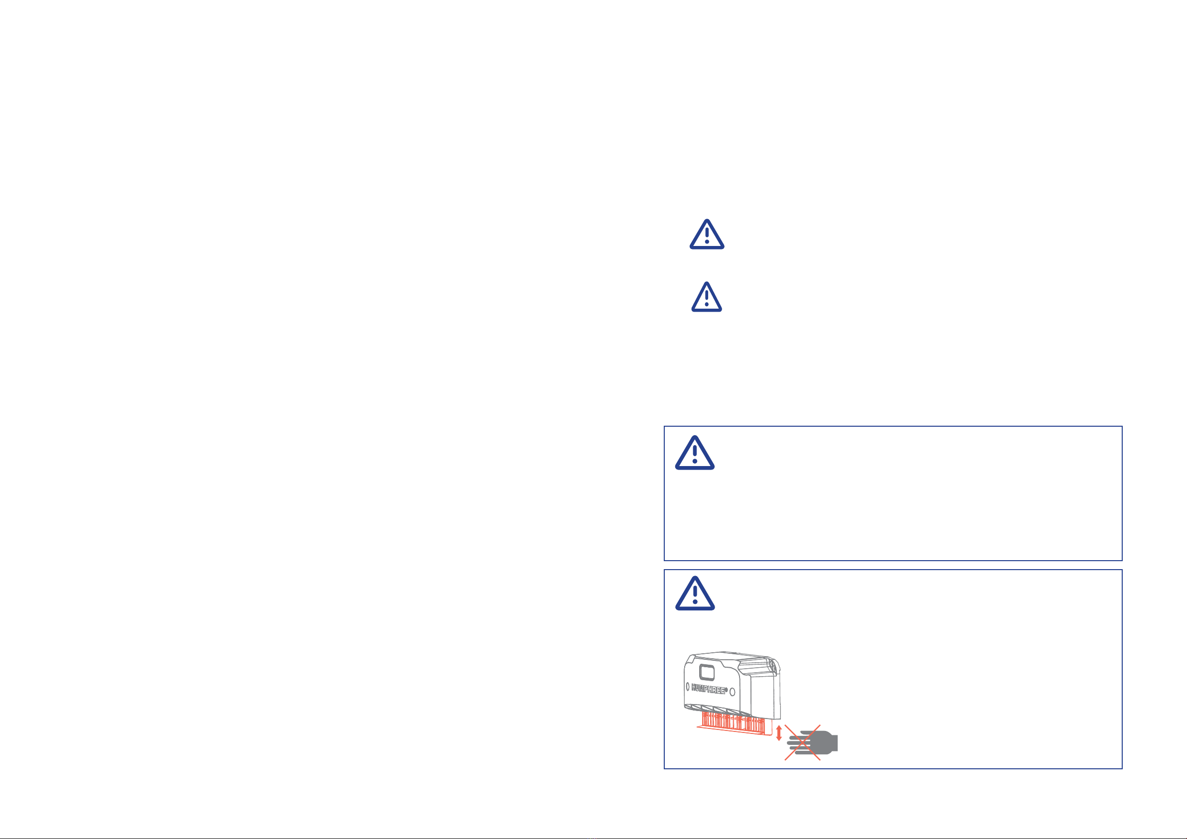
1 SAFETY INFORMATION
1.1 WARNINGS AND IMPORTANT NOTICES
1.2 INTERCEPTOR SAFEY PRECAUTIONS
2 ABOUT THIS MANUAL
2.1 INTENDED PRODUCT USAGE
2.2 INTENDED AUDIENCE
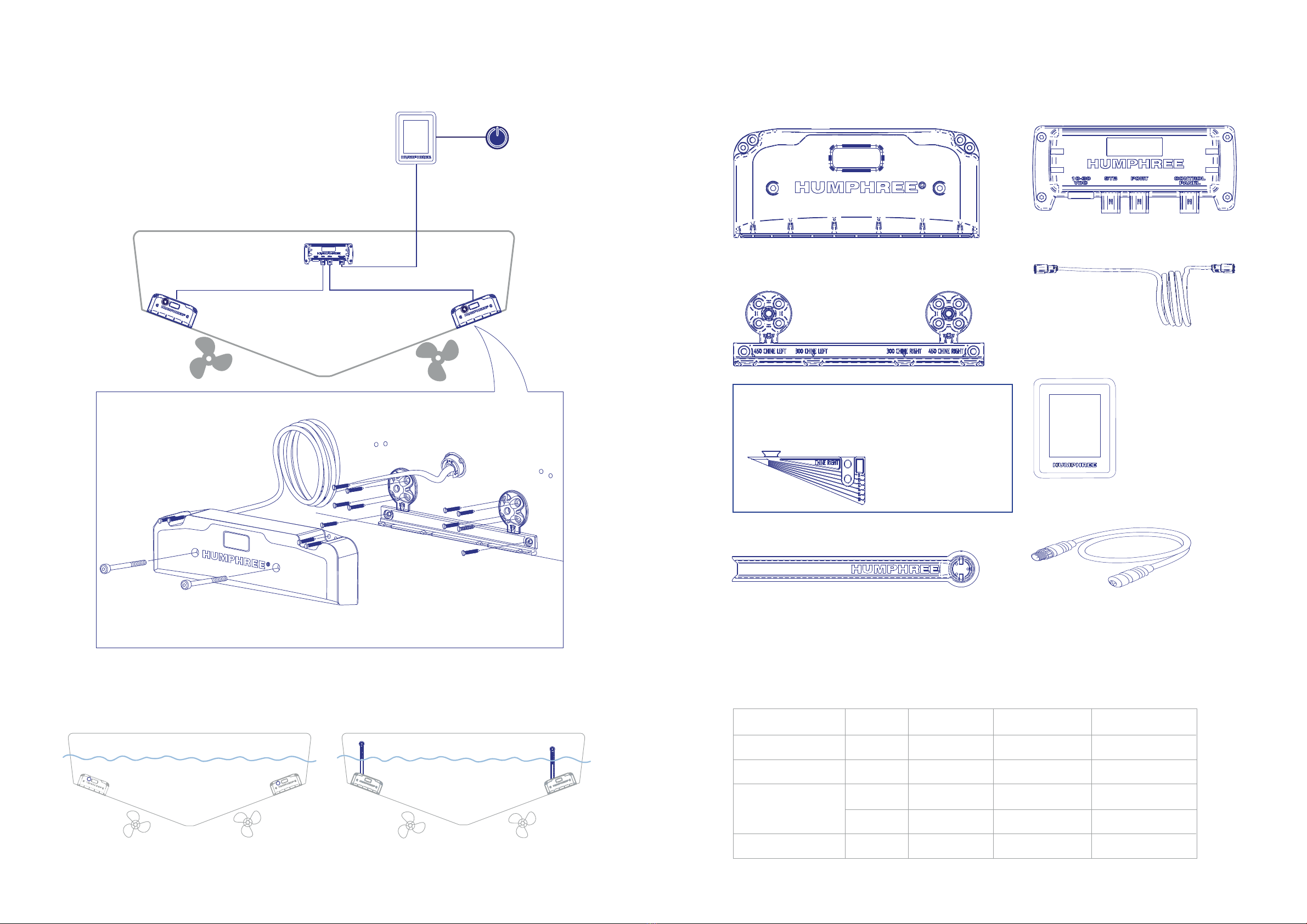
3 PRODUCT OVERVIEW
3.1 INTERCEPTOR MODELS
3.2 SYSTEM OVERVIEW
3.3 COMPONENTS
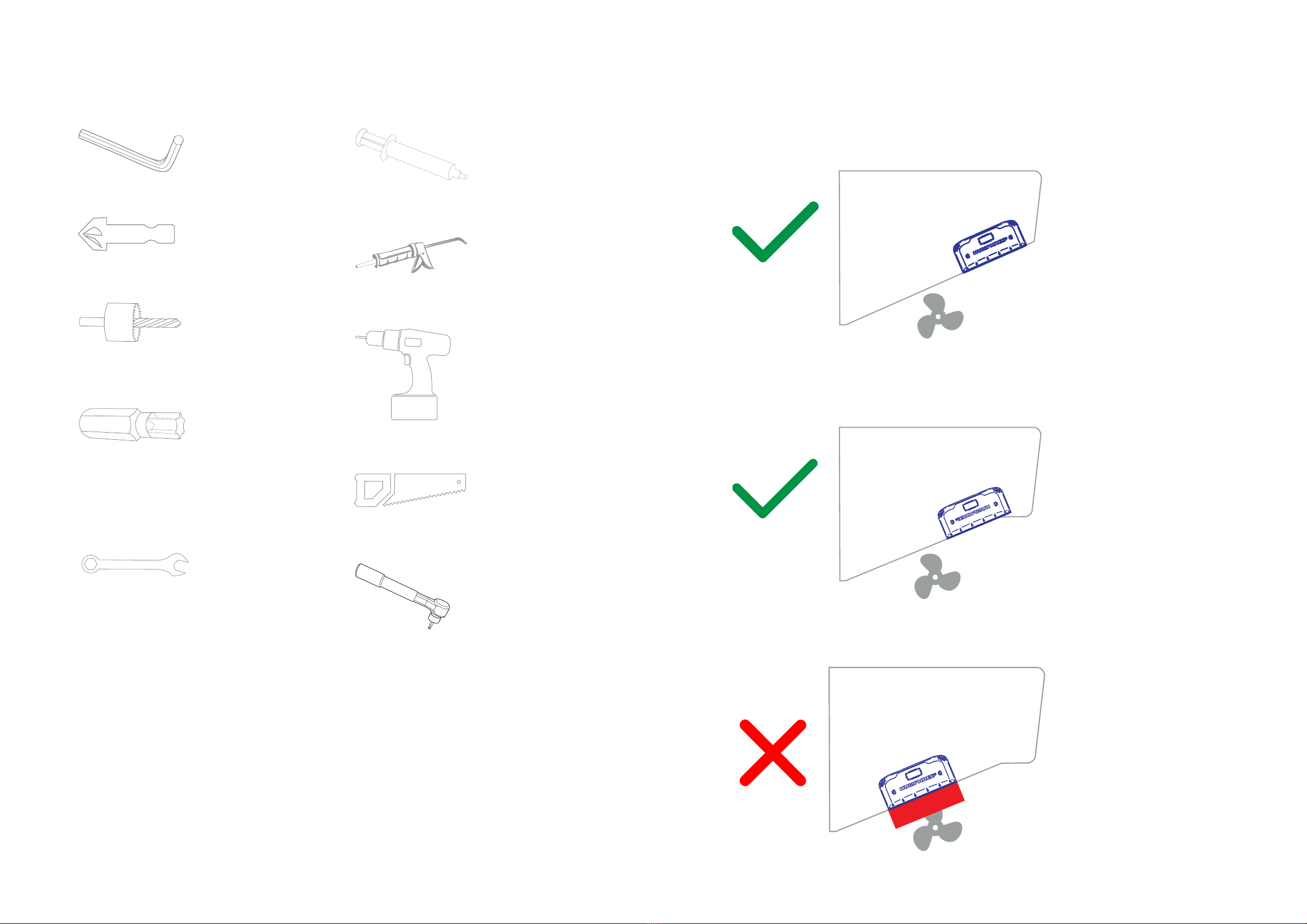
3.4 REQUIRED TOOLS
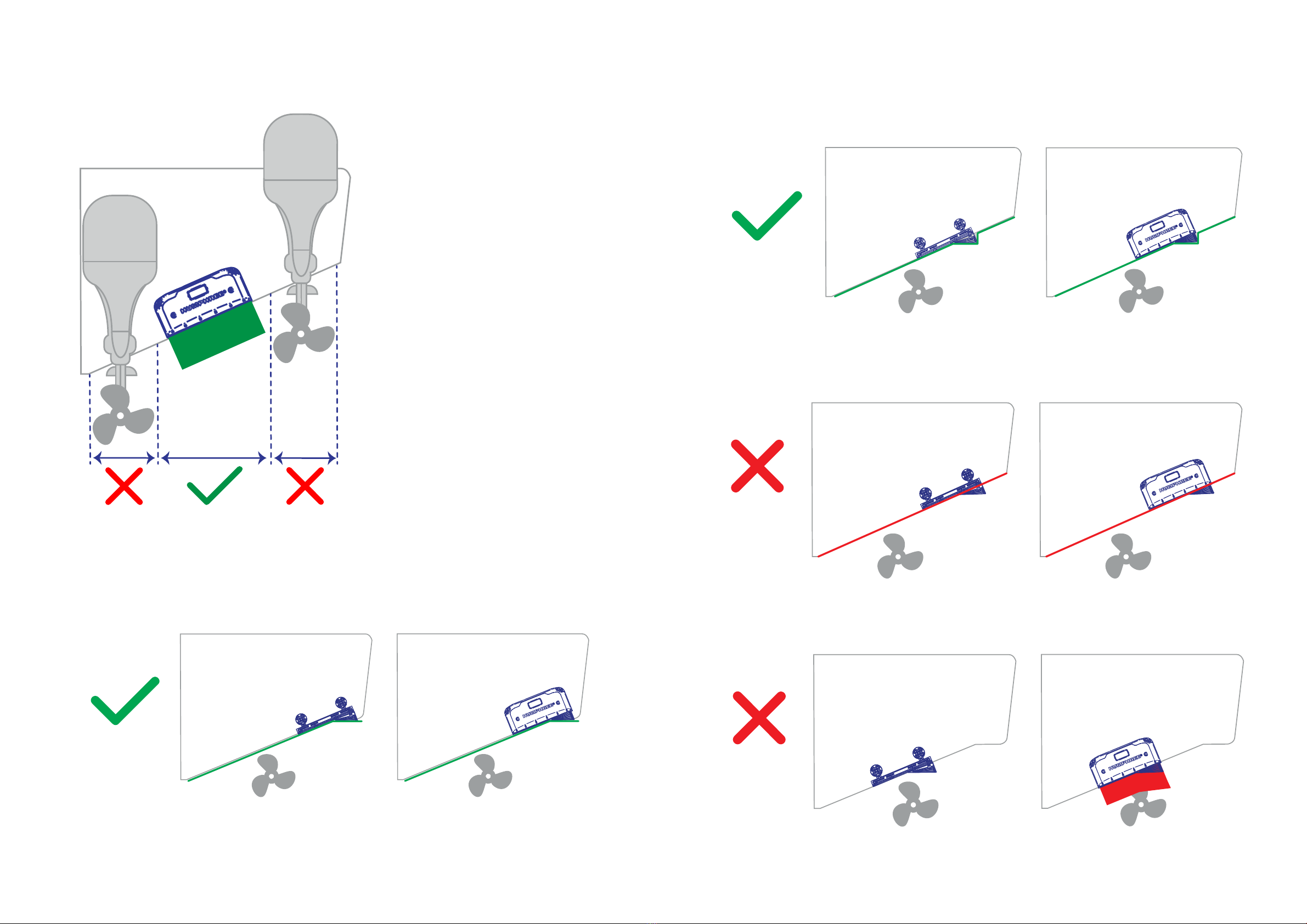
4 INTERCEPTOR MOUNTING GUIDELINES
4.1 STANDARD INTERCEPTOR MODELS (L300, L450)
4.2 FOR STERN DRIVES / OUTBOARDS
4.3 CHINE INTERCEPTOR MODELS (L300C, L450C)
4.4 INTERCEPTOR PLACEMENT
4.4.1 VERTICAL TRANSOM
4.4.2 ANGLED TRANSOM
4.5 BLADE MODIFICATIONS (CHINE ONLY)
5 PREPARATIONS
6 MOUNT THE INTERCEPTOR
6.1 MOUNT THE INTERCEPTOR BRACKET
6.2 MOUNT THE INTERCEPTOR
6.3 ADJUST THE CABLE GLAND
6.4 MOUNT THE CABLE COVER
7 MOUNT THE CONTROL UNIT
7.1 CONTROL UNIT PLACEMENT
7.1.1 DEFAULT ORIENTATION
7.1.2 ALTERNATIVE ORIENTATION
7.2 MOUNT THE CONTROL UNIT
8 MOUNT THE CONTROL PANNEL