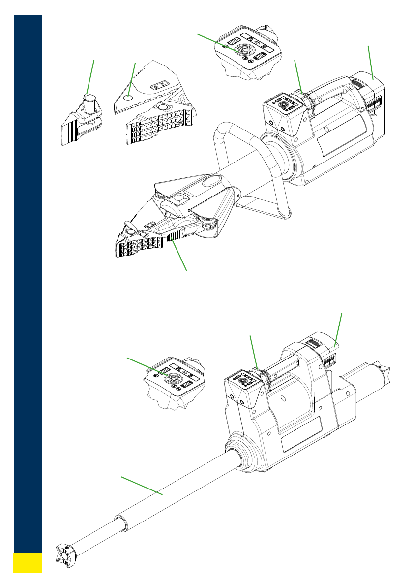
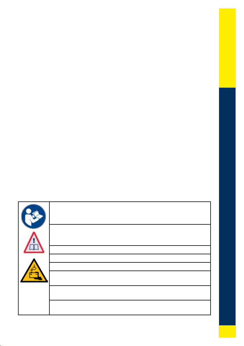
HURST EDraulic E3 User manual

E3 Operating Instructions
English IEspañol I Français IPortuguês
0.3
Maßstab
Datum/date
Schutzvermerkn. DIN ISO 16016
copyrightDIN ISO16016
Bearb./draw
Norm/norm
Gepr./check
Ers.f.:
Repl. f.:
Name
Kanten nach
edges to
DIN ISO 13715 Toleranzklasse
tolerance class
m / H
3
Alternativ:
Werkstoff:
0.1 0.1 0.2
0.5
6
3 6
30
Entst.aus:
develop.fr.: DIN
Bl.
Blatt
1000
2000
Masse
1.2
Werkstoff-Nr:
Werkstoff-Nr:
3-D_CAD
0.5 0.8
120
30
400
120
1000
400
2
2000
4000
+0,5
+0,2
ISO E
Weinstr. 39 91058Erlangen
LUKAS Hydraulik GmbH
IDEXCORPORATION
-0,2
-0,5
bis bis bis bis
über über über
über
über über
über
bis bis bis bis
12.02.2020
jkrug
1
\\legs0002\CAD\Archiv\120_Bedienungsanleitungen\110_Bilder_für_BA\Hurst_Deckblatt.iam
Hurst_Deckblatt
1 : 1
1
A0
-
sheet
sh.
scale
material:
alternativ:
material-no:
material-no:
mass
Zust.
Ind.
Anzahl
no. of
Änderung
change
Datum
date
Name
name
Allgem. Tol. nach
general tolerance to
DIN ISO 2768
Achtung!
Prototypen Zeichnung
Attention !
prototype drawing
-
271833085 / 08_2021

en
es
fr
pt
2
A ( 2 : 1 )
B ( 1,5 : 1 )
A
B
Achtung!
Prototypen Zeichnung
Attention !
prototype drawing
C ( 2 : 1 )
C
1
1
I.
II.
2
2
3
3
4
4
56

3
en
es
fr
pt
English��������������������������������������������������������������������4
Español�����������������������������������������������������������������18
Français����������������������������������������������������������������34
Português �������������������������������������������������������������50
eDraulic

en
es
fr
pt
4
English Translation of the original instructions
Subject to change
CONTENTS
1� Proper use���������������������������������������������������������������������������������������������������������5
2� Product safety and pictograms��������������������������������������������������������������������������5
3� Structure of the devices �����������������������������������������������������������������������������������8
4� Operating the devices ���������������������������������������������������������������������������������������9
5� Display and control panel��������������������������������������������������������������������������������10
6� Maintenance and care������������������������������������������������������������������������������������� 11
7� Troubleshooting ����������������������������������������������������������������������������������������������12
8� Explanation of pictograms for performance tables������������������������������������������15
9� Accessories�����������������������������������������������������������������������������������������������������17
10� Instructions regarding disposal �����������������������������������������������������������������������17

5
en
es
fr
pt
1. PROPER USE
The product described is an electro-hydraulic rescue device� The equipment is de-
signed for rescuing persons or material assets following a trac accident or natural
disaster and during other rescue missions� The rescue device must not be used to
perform lifting operations�
It must always be used in combination with HURST original accessories�
The manufacturer is not liable for damage resulting from improper use� The user
bears sole responsibility for such use�
The HURST E3 devices are suitable for underwater use to a depth of 3m�
For use in salt water, a special salt water rechargeable battery is required; it is
available from HURST as an accessory�
2. PRODUCT SAFETY AND PICTOGRAMS
The safety of the operator is the most important consideration in product design�
Furthermore, the instruction manual is intended to help you use HURST products
safely�
The generally applicable legal and other binding regulations pertaining to the
prevention of accidents and protection of the environment apply and are to be com-
plied with in addition to the operating instructions�
The device may only be operated by persons with appropriate training in the safety
aspects of such equipment, otherwise, there is a risk of injury�
We would like to point out to all users that they should carefully read, understand
and follow the instruction manual before using the device� All operating instructions
before using the product�
We further recommend that you have a qualied trainer show you how to use the
product�
Read the instruction manual for the lithium-ion battery and battery
chargers! Visit for a copy of the manual:
https://akkupower�info/ewxt-saftysheet�pdf
The battery housing may not be damaged or subjected to mechani-
cal stresses, as this may damage the cells inside�
Damaged batteries may no longer be used�
The battery may not be discharged deeply�
The battery may not be short-circuited�
Always allow wet batteries to dry before inserting into the charger�
Note and follow the information in the separate instructions for the
battery if it displays an error code�
The operating instructions for accessories must also be taken into
account!
Please ensure that the accessories you use are designed to with-
stand the maximum operating pressure of the rescue device�

en
es
fr
pt
6
Never work in a fatigued or intoxicated state!
Always use the equipment as described in the chapter “Proper
use”�
Please ensure that no body parts or clothing are caught between
the moving parts�
Always hold the equipment by the handles or housing� Do not touch
the piston rods of the rescue rams!
Working under suspended loads is not permitted where such loads
are only supported by hydraulic or electro-hydraulic devices� If
this work is unavoidable, suitable mechanical supports are also
required�
Wear a helmet!
Wear a face guard!
Wear protective clothing! Provides protection in hot and cold work-
ing environments and prevents injuries caused by sharp edges�
Wear protective gloves!
Wear safety shoes!
Always wear ear protection when working in noisy environments�
The noise of the equipment itself does not require ear protection�
Inspect the device before and after use for visible defects or dam-
age� The star grip valve must return to the central position by itself
without fail�
Report any changes immediately (including changes in operating
behavior)! If necessary, the device is to be shut down immediately
and secured!

7
en
es
fr
pt
Do not carry out any changes (additions or conversions) to the
device without obtaining the prior approval of HURST�
All safety instructions on the device must always be complete and
in a legible condition�
Any mode of operation which compromises the safety and stability
of the device is forbidden!
Safety devices must never be disabled!
Before switching on/starting up the device and during operation,
make sure that nobody will be endangered by this�
Repairs may only be performed by a trained service technician�
Only genuine HURST accessories and spare parts may be used�
Please note that when working with the equipment, material could
fall down or suddenly break free as a result of shearing, tearing or
breaking�
Observe all intervals for recurring tests and inspections as de-as de-
scribed in the chapter "Maintenance and care"�scribed in the chapter "Maintenance and care"�
The eDRAULIC devices and batteries are suitable for underwaterThe eDRAULIC devices and batteries are suitable for underwater
use to a depth of 3m and a duration of 60 minutes� The specialuse to a depth of 3m and a duration of 60 minutes� The special
battery for salt water operation must be used in salt and sea water�battery for salt water operation must be used in salt and sea water�
Swallowing or inhaling the hydraulic uids can be detrimental to
health� Avoid direct skin contact� Please note that handling hydrau-
lic uid can negatively aect biological systems.
Moving safety bolts, e�g� for removeable tips, must always be fully
inserted and locked�
When using chain sets, make sure that the chains are attached in a
straight line and that there are no knots in the chain�
When working near live components, high voltage ashovers and
the passage of current to the device are to be avoided�
Prevent the electrostatic charging of the device�
HURST eDRAULIC devices are not explosion-protected! Use in
explosion-protected areas is forbidden�

en
es
fr
pt
8
Please ensure that you do not become entangled in cables and trip
when working with or transporting the device�
Ensure adequate lighting at the location of use and on the way
there�
Always allow wet batteries to dry before inserting into the charger�
Always keep this instruction manual in an easily accessible location
close to the device at the place of operation�
eDRAULIC devices have protection class IP58� They can be used
for up to 60 minutes and to a depth of 3m under water�
When working with or storing the device, ensure that the function
and the safety of the equipment are not impaired by the eects of
high temperatures or that the device is not damaged in any way�
Note the temperature limits for operation and storage of the devic-
es� Consider that the device can heat up with longer-lasting use�
Before transporting the device, always ensure that the device,
battery and accessories are rmly secured.
Dispose of all removed parts, hydraulic uids and packaging mate-
rials properly�
3. STRUCTURE OF THE DEVICES
Page 2
1Device indicator (Figure M)
2Star grip valve
3 Battery
4Tool
5Removeable tips
6Draw / Bolt hole

9
en
es
fr
pt
4. OPERATING THE DEVICES
4.1 Inserting the battery
Push the battery from above into the battery slot until it locks in place (Figure A�)�
4.2 Removing the battery
Release the lock and remove the battery (Figure B�)�
4.3 Querying the battery status
Press the query button on the battery (Figure C�)� Note also the separate instruc-
tion manual for the battery�
4.4 Flashlight function of the battery
To switch on the ashlight, press the query button on the battery twice in quick
succession (Figure C.). To switch it o, press the query button again.
4.5 Switching on and off
To switch on, press the main switch (Figure M; No� 1)� The device is ready to op-
erate when the main switch and workspace lighting are illuminated blue� To switch
o, the main switch must be pressed for 0�5-1 second�
4.6 Actuating the star grip valve
The working action is triggered by turning the star grip valve� (Figure D�)�
Every rescue device has a deadman function� When the star grip is released,Every rescue device has a deadman function� When the star grip is released,
it returns to the center/neutral position automatically� This ensures the load isit returns to the center/neutral position automatically� This ensures the load is
retained�retained�
4.6.1 Cutting
Turn the star grip valve in the closing direction� (Figure E�)�
Position the cutter as perpendicular as possible to the object to be cut (Figure F�)�
Cut close to the pivot point of the blade (Figure G�)�
4.6.2 Spreading
Turn the star grip valve in the opening direction (Figure H�)�
Open a small gap at the start, then insert the spreader tips as far into the gap as
possible� Do not spread with the aluminum arms! (Figure J�)�
4.6.3 Pulling
Secure the traction device in the attachment / bolt hole (page 2; gure I; number 6) or
on the spreader tips� Actuate the star grip valve in the closing direction� (Figure E�)�
Note the separate instruction manual for the traction device�
4.6.4 Squeezing
Only squeeze in the squeezing area and with the squeezing plates of the spread-
er arms (Figure K�)� Actuate the star grip valve in the closing direction� (Figure E�)�
4.6.5 Peeling
Special peeling tips are needed for peeling (Figure L�)� Actuate the star grip valve
in the opening direction� (Figure H�)�

en
es
fr
pt
10
4.6.6 Pushing
Place the rescue rams between the object to be pushed and actuate the star grip
valve in the extending direction� (Figure H�)�
4.7 Removing the tips
The removeable tips are connected to the device arm with bolts� To remove the
tips, the bolts must be fully pushed in and then fully locked again (page 2; gure I;
numbers 5+6)
4.8 Automatic switch-off
If the rescue device is not activated for a period of 60 minutes, it switches o auto-
matically�
4.9 Dismantling/shutting down after operation
Once work has been completed, the device arms should be closed until the tips are
only a few millimeters apart and the ram piston should be fully retracted and then
extended a few millimeters� This relieves hydraulic and mechanical strain on the
device� For transport and storage, all devices should be secured and not loosely
stored�
5. DISPLAY AND CONTROL PANEL
5.1 Main switch (Figure M; No. 1)
For cutting and combination devices, the main switch includes the indicator for the
cutting angle monitoring� (Figure F�)� If the device twists to the right or left by an
angle critical for the blade stability during the cutting process, the blue ring changes
color to red� Attention! Check whether you can complete the cutting process with-
out danger or whether you must reposition on the object to be cut�
5.2 Battery indicator (Figure M; No. 2)
The battery indicator indicates the current battery capacity�
5.3 Load indicator (Figure M; No. 3)
The load indicator scale indicates in what pressure range the tool is while working
and provides information about the remaining capacity�
5.4 Control light for the turbo function (Figure M; No. 4)
The star grip can be moved by 20° in any direction; with a move starting at 15°,
the turbo function is activated, the device moves faster� The turbo function is only
available in the low-pressure range�
5.5 Control light for saltwater battery (Figure M; No. 5)
The control light indicates when a saltwater battery is plugged into the device�

11
en
es
fr
pt
5.6 Warning light for electronics temperature (Figure M; No. 6)
The device independently monitors the temperature of the electronics and emits a
warning if the temperature reaches a critical range� In case of increased electronics
temperature, no more turbo mode is available�
Furthermore, the device monitors the battery temperature, and with a cell tem-
perature of less than -10° C, it reduces the speed in order to warm up the battery�
As soon as the battery is warm enough, all functions are available again at normal
speed�
5.7 Illuminated direction indicator (Figure M; No. 7)
Depending on the direction in which the star grip is moved, the device indicates the
motion direction in the display eld.
6. MAINTENANCE AND CARE
6.1 General maintenance
A visual check is to be carried out after each use� After every use, the lubrication of
the moving parts and bolts must be checked and topped o with a suitable grease,
if necessary� The torque of the central bolt on cutting and combination tools must
also be checked. To do so, check the specications in the spare parts lists.
Any dirt must be removed with a damp cloth� The rescue device should not come
into contact with acids or alkalis� If this is unavoidable, clean the device immediate-
ly afterwards�
An annual inspection of the device is due each year and must be documented�
This annual inspection must be conducted by a person with the necessary exper-
tise� A function and load test must be conducted every three years or in case of any
safety concerns� Only testing equipment approved by HURST may be used�
Please also observe the relevant domestic and international regulations on the
maintenance intervals of rescue devices�
6.2 Maintenance after underwater use
• Remove the battery after use� Rinse the device and battery several times in
fresh, clean water. Immerse the device completely in order to ll the housing
with clean water� Lift the device out and let it drain completely� Depending on
the type of water (mud, sludge, algae, salt water, etc�) in which the device was
used, repeat these steps another 2-5 times�
• Wipe the device and the battery with a clean, dust-free and damp cloth in
order to remove dirt and deposits�
• Leave the device and battery dry at room temperature in a well-ventilated
location� 36-48 hours is recommended� During this drying time, the device is
completely operational�
• Lubricate all exposed steel parts (shear blade, pressure piece, etc�) with anti-
corrosion agent� The contacts in the battery shaft may not be lubricated�
• Perform function test�

en
es
fr
pt
12
6.3 Sharpening the blades
Any burrs may be removed and the blade smoothed only in the grinding area (Pic-
ture)! Break outs or deep cracks cannot be ground away; in such cases the blades
must be replaced�
Tools required:
1� Clamping device (e�g�, vise) with jaw protection
2� Grinder (e�g� angle grinder or belt grinder) with abrasive having a grain size of
80. A diamond le is adequate for small burrs.
Procedure:
1� Clamp the blade securely into the clamping device so that it cannot move,
leaving the grinding area exposed (Picture P�)�
2� Carefully de-burr the grinding area with the grinding machine (Picture P�)�
6.4 Repair
Repairs may only be performed by HURST or personnel trained by HURST�
When doing so, observe the information in the spare parts lists�
6.5 Rechargeable batteries
If the devices are not used for a longer period, we recommend starting up the
device with the appropriate battery 5 times after 30 days� Then charge the battery
completely�
This supports optimal function and availability of the battery and devices�
7. TROUBLESHOOTING
Fault Check Cause Solution
The motor does
not start after
activating the star
grip
The main switch
is not illuminated
although it has not
been switched o
Device has not
been used for
60 minutes and
has switched o
automatically
Switch the device
on again with the
main switch
Battery dead Recharge the
battery or use
another battery
Battery defective Replace battery
Blue ring on main
switch lights up
There is a defect
in the electronics
Repair by an
authorized dealer,
by personnel
specially trained
by HURST, or by
HURST itself

13
en
es
fr
pt
Fault Check Cause Solution
Motor always runs Star grip in middle
position, device
does not move,
main switch illu-
minated or lights
up?
Error in electron-
ics
Switch o device
on the main
switch� Remove
the battery�
Repair by an
authorized dealer,
by personnel
specially trained
by HURST, or by
HURST itself
Rescue device
moves jerkily
when operated
Air in the hydraulic
system
Repair by an
authorized dealer,
by personnel
specially trained
by HURST, or by
HURST itself
Rescue device
moves slowly
when operated
Temperature of
device and battery
below -10°C
Cold ambient
temperature
Use devices nor-
mally, device will
warm up with use
Check charging
state display
Rechargeable bat-
tery almost dead
Recharge the
battery or use
another battery
Turbo function not
available
Ambient tempera-
ture low
Use devices nor-
mally, device will
warm up with use
Changeover pres-
sure reached
Perform move-
ment without turbo
function
Warning light for
electronics tem-
perature lights up
Electronics tem-
perature too high
Perform move-
ment without turbo
function
Cylinder pistons
do not move when
operated
Battery fully
charged?
Main switch illumi-
nated?
Battery dead Charge battery
Battery defective Replace battery
Device defective Repair by an
authorized dealer,
by personnel
specially trained
by HURST, or by
HURST itself

en
es
fr
pt
14
Fault Check Cause Solution
Device doesn’t
perform at its
given power
Device defective Repair by an
authorized dealer,
by personnel
specially trained
by HURST, or by
HURST itself
Following release,
the star grip
doesn’t return to
the central/neutral
position
Casing damaged
or star grip oper-
ation not working
smoothly?
Damage to the
torsion spring for
reset
Repair by an
authorized dealer,
by personnel
specially trained
by HURST, or by
HURST itself
Soiled valve or
star grip
Defective valve
Other mechanical
damage
(e�g� star grip)
Hydraulic uid
leaks on the pis-
ton rod
Defective rod seal Repair by an
authorized dealer,
by personnel
specially trained
by HURST, or by
HURST itself
Damage to the
piston
The useful operat-
ing time between
the individual
charging cycles
is less than 5
minutes, despite
charging the bat-
teries according to
the instructions
Battery defective Replace battery

15
en
es
fr
pt
8. EXPLANATION OF PICTOGRAMS FOR
PERFORMANCE TABLES
All technical data is subject to tolerances� For this reason, there may be slight devi-
ations between the data in the table and that of your device�
8.1 Technical data
The technical data of the devices can be found on page 66�
Symbol Description Remarks / abbreviationabbreviation
Length (without battery)
Length retracted →L←
Length extended ←L→
Stroke Hg
Piston extension 1 H1
Piston extension 2 H2
Force piston 1 HSF1
Force piston 2 HSF2
Width (without battery)
Height
Weight (without battery)
Weight with battery 5 Ah
9 Ah
Min� cutting opening
Cutting opening in accor-
dance with EN
Max� cutting force (rear-most cutting point)
Nominal voltage U
Power consumption at
nominal load
I
Maßstab 1:10
Rechtecke für Maßband 50x23, Strich für Teilung 11,5 lang
L
Maßstab 1:10
Rechtecke für Maßband 50x23, Strich für Teilung 11,5 lang
L
Hub
Laus
Maßstab 1:10
Rechtecke für Maßband 50x23, Strich für Teilung 11,5 lang
Hg / H1 / H2
L
Maßstab 1:10
Rechtecke für Maßband 50x23, Strich für Teilung 11,5 lang
B
Maßstab 1:10
Rechtecke für Maßband 50x23, Strich für Teilung 11,5 lang
H
KG
A
Sö
Maßstab 1:10
Rechtecke für Maßband 50x23, Strich für Teilung 11,5 lang

en
es
fr
pt
16
Symbol Description Remarks / abbreviationabbreviation
Protection class (up to 60 minutes and a
depth of up to 3 meters)
Round material Ø
Cutting class (EN 13204)
Cutting class (NFPA 1936)
Opening width Ls
Spreading force HSF/LSF
Min� spreading force min� Fs
(25mm from the tips)
Max� spreading force max� Fs
*) computed value
Traction path Lz
Pulling force HPF/LPF
Max� pulling force max� Fz
(with accompanying
chain set)
Operating temperature
range
TB
Storage temperature
range
TL
Acoustic pressure level at
full load
LpAV
Acoustic power level at
full load
LwAV
8.2 Oscillation/vibrations
The total oscillation value / vibration value to which human arms should be ex-
posed to is typically below 2�5 m/s²�
Higher values may be measured for short periods as a result of interaction with the
materials to be processed�
(The oscillations / vibrations were determined in accordance with DIN EN ISO 20643�)
I P
Lz
Ls
Maßstab 1:10
Rechtecke für Maßband 50x23, Strich für Teilung 11,5 lang

17
en
es
fr
pt
9. ACCESSORIES
9.1 Batteries
Only HURST lithium-ion rechargeable batteries may be used to operate eDRAULIC
devices� Observe the separate operating instructions for the lithium-ion battery!
A special salt water battery is available from HURST for use in salt and sea water�
9.2 Battery charger
Only the "eDRAULIC Power Pack Charger" may be used for the lithium-ion batter-
ies� Observe the separate operating instructions for the charger�
9.3 Power Supply
For eDRAULIC devices, there is a power supply with which the devices can be
connected directly to a power outlet� The power supply transforms the alternating
current into direct current, so it can be used in place of the battery� Observe the
separate operating instructions for the power supply�
9.4 Chain sets
Chain sets and pulling adapters are required in order to perform pulling operations
with the eDRAULIC spreaders and combination tools (see chapter, “Pulling”)�
Observe the separate operating instructions for the chains sets�
10. INSTRUCTIONS REGARDING DISPOSAL
Please dispose of all packaging materials and removed items correctly� Electrical
equipment, accessories and packaging should always be disposed of in an envi-
ronmentally compatible way�
Only for EU countries:
Do not dispose of electrical equipment with your household waste!
According to the European Directive 2002/96/EC governing electrical and electron-
ic waste and their application in national legislation, old electrical equipment must
be separately collected and recycled in an environmentally compatible manner�

en
es
fr
pt
18
Español Traducción del manual de instrucciones original
Reservado el derecho a modicaciones
CONTENIDO
1� Uso previsto ����������������������������������������������������������������������������������������������������� 19
2� Seguridad del producto y pictogramas������������������������������������������������������������� 19
3� Estructura de los equipos �������������������������������������������������������������������������������� 22
4� Utilización de los equipos��������������������������������������������������������������������������������� 23
5� Campo de visualización y manejo�������������������������������������������������������������������� 24
6� Mantenimiento y cuidados ������������������������������������������������������������������������������� 25
7� Análisis de averías������������������������������������������������������������������������������������������� 27
8� Explicación de los pictogramas de las tablas de rendimiento�������������������������� 30
9� Accesorios�������������������������������������������������������������������������������������������������������� 32
10� Indicaciones para la eliminación ���������������������������������������������������������������������� 32

19
en
es
fr
pt
1. USO PREVISTO
El producto descrito es una herramienta de rescate electro-hidráulica� Está pre-
vista para el rescate de personas o bienes materiales en accidentes de tráco,
catástrofes naturales u otras intervenciones de rescate� La herramienta de rescate
no permite ejecutar procesos de elevación�
Únicamente puede utilizarse en combinación con accesorios originales de HURST�
El fabricante no asume responsabilidad alguna por los daños derivados de un uso
indebido� El usuario será responsable exclusivo de un uso semejante�
Los equipos E3 de HURST son aptos para aplicaciones subacuáticas hasta 3 m�
Para el uso en agua salina es necesaria una batería especial para agua salina,
disponible en HURST como accesorio�
2. SEGURIDAD DEL PRODUCTO Y PICTOGRAMAS
La seguridad del operario es lo más importante a la hora de diseñar el producto�
Además, el manual de instrucciones puede resultar de ayuda para utilizar los pro-
ductos HURST sin peligro�
Además del manual, han de tenerse en cuenta y hacerse cumplir todas las normas
de valor general, legales y otras normas vinculantes relativas a la prevención de
accidentes y a la protección del medio ambiente�
El equipo solo debe ser manipulado por personas adecuadamente instruidas y
con formación técnica en el campo de la seguridad, puesto que en caso contrario
existe peligro de lesiones�
Aconsejamos a todos los usuarios que lean atentamente el manual de instruc-
ciones antes de utilizar el equipo� Todas las instrucciones incluidas en él deben
observarse sin excepción alguna�
También recomendamos que le instruya una persona experta en el uso de producto�
¡Observe el manual de instrucciones de la batería de iones de litio
y del cargador! Lo encontrará en:
https://akkupower�info/ewxt-saftysheet�pdf
La carcasa de la batería no puede sufrir daños ni exponerse a car-
gas mecánicas puesto que esto podría dañar las celdas situadas
en el interior� Las baterías dañadas no deben seguir usándose�
La batería no debe descargarse por completo�
La batería no debe cortocircuitarse�
Enchufe la batería al cargador únicamente cuando esté seca�
Seque la batería antes de enchufarla si estuviera mojada�
Observe y siga las indicaciones del manual especíco de la batería
si esta mostrara un código de error�
¡Observe las instrucciones de uso de los accesorios!
Preste atención a que los accesorios utilizados puedan soportar la
presión de servicio máxima de la herramienta de rescate�

en
es
fr
pt
20
¡Nunca trabaje estando muy cansado o bajo los efectos del alcohol
u otras sustancias!
Utilice el equipo exclusivamente según se describe en el capítulo
«Uso previsto»�
Cerciórese de que ninguna parte del cuerpo ni la ropa queden
atrapados entre los componentes móviles del equipo�
Toque el equipo únicamente por los asideros o la carcasa�
¡No toque bajo ningún concepto los vástagos de los pistones de los
cilindros de rescate!
Está prohibido trabajar debajo de cargas si estas están soportadas
exclusivamente por aparatos hidráulicos o electrohidráulicos�
Si este trabajo resulta imprescindible, será necesario añadir su-
cientes apoyos mecánicos�
¡Lleve un casco de protección!
¡Lleve protección facial!
¡Lleve ropa de protección contra entornos de trabajo calientes y
fríos y contra lesiones provocadas por bordes agudos!
¡Lleve guantes de protección!
¡Lleve calzado de seguridad!
Lleve protección auditiva en caso de tener que trabajar en entornos
con un nivel de ruido elevado� El volumen del equipo no requiere el
uso de protección auditiva�
Verique antes y después del uso si el equipo tiene fallos o daños
visibles� La válvula de empuñadura en estrella debe volver por sí
misma en todo momento a la posición central�
¡Notique de inmediato cualquier cambio (también de funciona-
miento)! ¡Si fuese necesario, pare inmediatamente el equipo y
retírelo del servicio!
Table of contents
Languages:
Other HURST Tools manuals
Popular Tools manuals by other brands

Hercules
Hercules HD67B Owner's manual & safety instructions

Elliott
Elliott ET720-1800 Operating and maintenance instructions

Tüchler
Tüchler KABUKLIP operating manual

Powerfix Profi
Powerfix Profi PFRS 1.5 A1 operating instructions

Sealey
Sealey PFT07.V2 instruction manual

Toya
Toya VOREL 81072 Original instructions

Jet
Jet HB-1697H Operating instructions and parts manual

Blue Giant
Blue Giant BLUE GENIUS SERIES Installation & owner's manual

LEERS
LEERS L1 manual

DR Power Equipment
DR Power Equipment PTO POST HOLE DIGGER Safety & Operating Instructions

Gardena
Gardena 2641 Assembly instructions

Rehau
Rehau RAUTOOL A-LIGHT2 Operating instructions and technical information