Husqvarna Gear Drive User manual
Other Husqvarna Lawn And Garden Equipment manuals

Husqvarna
Husqvarna Fast TractorYTH24K48 Use and care manual

Husqvarna
Husqvarna 525PT5S User manual
Husqvarna
Husqvarna TR317C User manual

Husqvarna
Husqvarna Automower 305 User manual
Husqvarna
Husqvarna EPOS User manual
Husqvarna
Husqvarna HA200 User manual
Husqvarna
Husqvarna LTB48A User manual

Husqvarna
Husqvarna 968999195 User manual

Husqvarna
Husqvarna AUTOMOWER 310 User manual

Husqvarna
Husqvarna 650RTTA User manual

Husqvarna
Husqvarna DT18 User manual
Husqvarna
Husqvarna BMP 335 User manual
Husqvarna
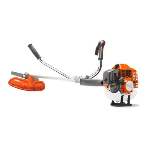
Husqvarna 236R User manual

Husqvarna
Husqvarna AUTOMOWER 450X User manual
Husqvarna
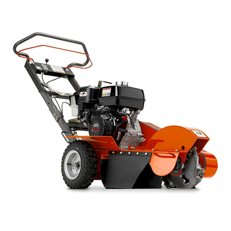
Husqvarna SG13 Guide
Husqvarna
Husqvarna SC18 Instruction manual
Husqvarna
Husqvarna AUTOMOWER 420 User manual
Husqvarna
Husqvarna ESA850 User manual

Husqvarna
Husqvarna DT18 C User manual

Husqvarna
Husqvarna Automower 305 User manual
Popular Lawn And Garden Equipment manuals by other brands

Vertex
Vertex 1/3 HP Maintenance instructions

GHE
GHE AeroFlo 80 manual

Millcreek
Millcreek 406 Operator's manual

Land Pride
Land Pride Post Hole Diggers HD25 Operator's manual

Yazoo/Kees
Yazoo/Kees Z9 Commercial Collection System Z9A Operator's & parts manual

Premier designs
Premier designs WindGarden 26829 Assembly instructions

AQUA FLOW
AQUA FLOW PNRAD instructions

Tru-Turf
Tru-Turf RB48-11A Golf Green Roller Original instruction manual

BIOGROD
BIOGROD 730710 user manual

Land Pride
Land Pride RCF2784 Operator's manual

Makita
Makita UM110D instruction manual

BOERBOEL
BOERBOEL Standard Floating Bar Gravity Latch installation instructions
