Husqvarna WS 440HF Instruction manual

HUSQVARNA CONSTRUCTION PRODUCTS
Workshop manual
WS440HF, WS482HF,
PP440HF, PP480HF,
PP490HF

2
LEGEND

2
3
TABLE OF CONTENTS
3. Literature
Workshop Manual���������������������������������������������������������������������������������������������������������������������������������������� 7
Spare Parts Catalogue����������������������������������������������������������������������������������������������������������������������������������� 7
Operator’s Manual���������������������������������������������������������������������������������������������������������������������������������������� 7
4. Safety Instructions
General ����������������������������������������������������������������������������������������������������������������������������������������������������������� 8
Warning and Information ��������������������������������������������������������������������������������������������������������������������������� 8
ESD General Notice������������������������������������������������������������������������������������������������������������������������������������� 8
Emergency Stop Button������������������������������������������������������������������������������������������������������������������������������� 9
Start Blade Rotation ������������������������������������������������������������������������������������������������������������������������������������� 9
Transport and Storage ���������������������������������������������������������������������������������������������������������������������������������� 9
5.Tools and Special Tools
Tools �������������������������������������������������������������������������������������������������������������������������������������������������������������10
6. Components - Navigation
WS 482 HF ��������������������������������������������������������������������������������������������������������������������������������������������������14
PP 490 (External)����������������������������������������������������������������������������������������������������������������������������������������15
PP 490 (Internal)�����������������������������������������������������������������������������������������������������������������������������������������16
7. Service and Maintenance
The service-related differences between the WS480 and WS440����������������������������������������������������������17
The service-related differences between the PP480 and PP440�������������������������������������������������������������18
The service-related differences between the PP480 and PP490�������������������������������������������������������������19
Funktion Test WS400 HF��������������������������������������������������������������������������������������������������������������������������20
Function Test Power Pack��������������������������������������������������������������������������������������������������������������������������21
Function test Remote Control������������������������������������������������������������������������������������������������������������������22
WS400 HF Service ��������������������������������������������������������������������������������������������������������������������������������������25
Power Pack Service��������������������������������������������������������������������������������������������������������������������������������������27
RC Unit Sevice ��������������������������������������������������������������������������������������������������������������������������������������������27
Service 100h�������������������������������������������������������������������������������������������������������������������������������������������������28
Service 200h�������������������������������������������������������������������������������������������������������������������������������������������������29
8.Technical Information andTroubleshooting
General ���������������������������������������������������������������������������������������������������������������������������������������������������������31
Temp Sensors�����������������������������������������������������������������������������������������������������������������������������������������������31
Fault Codes PRIME tools��������������������������������������������������������������������������������������������������������������������������32
Error Message (LED indicator) PRIME tools�����������������������������������������������������������������������������������������34
Fault Codes��������������������������������������������������������������������������������������������������������������������������������������������������35
Trouble Shooting Tree ��������������������������������������������������������������������������������������������������������������������������������37
Description of LED codes�������������������������������������������������������������������������������������������������������������������������67

4
2TABLE OF CONTENTS
9. Remote Control
RC Service Menu ����������������������������������������������������������������������������������������������������������������������������������������71
10. Repair Instructions Wall Saw
10.1. Blade Gard
Replacing the Bearings in the Blade Guard Guide Wheels ������������������������������������������������������������������72
Disassembly���������������������������������������������������������������������������������������������������������������������������������������������72
Assembly��������������������������������������������������������������������������������������������������������������������������������������������������72
Calibrating the Two Adjustable Wheels���������������������������������������������������������������������������������������������������73
Checking that the Blade Guard Guide is parallel with the Blade��������������������������������������������������������73
Remove Blade Flange ���������������������������������������������������������������������������������������������������������������������������������74
Renovate Blade Flange �������������������������������������������������������������������������������������������������������������������������������74
10.2. Saw Arm
Detach Arm/Housing�������������������������������������������������������������������������������������������������������������������������������� 77
Inspect the Clutch�������������������������������������������������������������������������������������������������������������������������������������� 78
Disassemble Arm ���������������������������������������������������������������������������������������������������������������������������������������� 79
Remove Clutch Gear Shafts ����������������������������������������������������������������������������������������������������������������������80
Inspect Clutch Gear Shafts �����������������������������������������������������������������������������������������������������������������������82
Align Clutch Gear Shafts (Only WS482)������������������������������������������������������������������������������������������������83
Disassemble the Gear Selector (Only WS482)����������������������������������������������������������������������������������������84
Install the Gear Selector (Only WS482) ��������������������������������������������������������������������������������������������������85
Reinstall Clutch Shafts�������������������������������������������������������������������������������������������������������������������������������86
Click for 3D steps���������������������������������������������������������������������������������������������������������������������������������������86
Replace Bearings �����������������������������������������������������������������������������������������������������������������������������������������89
Replace Axle Bearing����������������������������������������������������������������������������������������������������������������������������������91
Assemble Bearings���������������������������������������������������������������������������������������������������������������������������������������93
Mount Saw Arm �����������������������������������������������������������������������������������������������������������������������������������������95

2
5
TABLE OF CONTENTS
10.3. Saw Head
Remove Covers�������������������������������������������������������������������������������������������������������������������������������������������� 98
Remove Handle/Blade Guard Mount����������������������������������������������������������������������������������������������������� 98
Dismantling the Saw Head Electronics ���������������������������������������������������������������������������������������������������99
Click for 3D steps���������������������������������������������������������������������������������������������������������������������������������������99
Remove Feed Motors �������������������������������������������������������������������������������������������������������������������������������101
Remove Feed Motor Gearbox�����������������������������������������������������������������������������������������������������������������102
Adjust play on Feed Motor Gearbox�����������������������������������������������������������������������������������������������������103
Reassemble the Feed Motor Gearbox ����������������������������������������������������������������������������������������������������104
Remove Motor ������������������������������������������������������������������������������������������������������������������������������������������105
Dismantle the Motor �������������������������������������������������������������������������������������������������������������������������������106
Replace Motor Bearings���������������������������������������������������������������������������������������������������������������������������107
Replace the Motor Temp Sensor �����������������������������������������������������������������������������������������������������������109
Assemble the Motor ���������������������������������������������������������������������������������������������������������������������������������110
Remove Feed Shaft �����������������������������������������������������������������������������������������������������������������������������������111
Measure the Teeth Wear���������������������������������������������������������������������������������������������������������������������������112
Inspect the Track Feed Slip Clutch ��������������������������������������������������������������������������������������������������������112
Disassemble the Track Feed Slip Clutch������������������������������������������������������������������������������������������������113
Replace the Needle Bearing ��������������������������������������������������������������������������������������������������������������������114
Assemble the Track Feed Slip Clutch �����������������������������������������������������������������������������������������������������115
Replace the Arm Feed Bearing����������������������������������������������������������������������������������������������������������������116
Assemble the Feed Shaft���������������������������������������������������������������������������������������������������������������������������118
Click for 3D steps�������������������������������������������������������������������������������������������������������������������������������������118
Assemble Feed Motors �����������������������������������������������������������������������������������������������������������������������������120
Click for 3D steps�������������������������������������������������������������������������������������������������������������������������������������120
Assemble the Saw Head Electronics �������������������������������������������������������������������������������������������������������121
Click for 3D steps�������������������������������������������������������������������������������������������������������������������������������������121

6
2TABLE OF CONTENTS
11. Repair Instructions Power Pack
Opening the PP 490 ���������������������������������������������������������������������������������������������������������������������������������124
Replacing the Cover Seals������������������������������������������������������������������������������������������������������������������������125
Replacing the CAN Bus Contact �����������������������������������������������������������������������������������������������������������126
Replacing the Voltage Inducator Lamp �������������������������������������������������������������������������������������������������127
Replacing the Power Inlet and the Residual current device (RCD)���������������������������������������������������128
Replacing the Single Phase Socket����������������������������������������������������������������������������������������������������������130
Replacing the Emergency Stop Button��������������������������������������������������������������������������������������������������131
Replacing the Harting Connector Assembly, Wall Saw �����������������������������������������������������������������������132
Replacing the Main Contactor ���������������������������������������������������������������������������������������������������������������134
Replacing the Transformer ����������������������������������������������������������������������������������������������������������������������135
Remove the WS contactor �����������������������������������������������������������������������������������������������������������������������136
Remove 15A fuse boxes ���������������������������������������������������������������������������������������������������������������������������137
Remove the Prime Contactor �����������������������������������������������������������������������������������������������������������������138
Remove DIN-rail bracket �������������������������������������������������������������������������������������������������������������������������138
Replacing the Main Board�����������������������������������������������������������������������������������������������������������������������139
Replacing Controller Board ��������������������������������������������������������������������������������������������������������������������141
Water Valve�������������������������������������������������������������������������������������������������������������������������������������������������142
Dismantle the Inverter Board �����������������������������������������������������������������������������������������������������������������143
Assemble the Inverter Board ������������������������������������������������������������������������������������������������������������������145
12. Firmware Upgrade
What is what on the Multiprogrammer ������������������������������������������������������������������������������������������������146
Firmware update for PP440, PP480 and PP490������������������������������������������������������������������������������������146
Inverter side ������������������������������������������������������������������������������������������������������������������������������������������147
Main Board side�����������������������������������������������������������������������������������������������������������������������������������149
Firmware update for PP440 -Controller board only ����������������������������������������������������������������������������153
Upgrade the RC-unit rmware ���������������������������������������������������������������������������������������������������������������155
Function test ���������������������������������������������������������������������������������������������������������������������������������������������155
13.Wiring Diagrams
Electrical Drawings �����������������������������������������������������������������������������������������������������������������������������������156
WS482 Saw Head Circuit Board��������������������������������������������������������������������������������������������������������156
PP480�����������������������������������������������������������������������������������������������������������������������������������������������������157
PP490 4-pin ������������������������������������������������������������������������������������������������������������������������������������������158
PP490 5-pin�������������������������������������������������������������������������������������������������������������������������������������������159
Simplied Wiring Diagram���������������������������������������������������������������������������������������������������������������������160
PP480�����������������������������������������������������������������������������������������������������������������������������������������������������160
PP490�����������������������������������������������������������������������������������������������������������������������������������������������������161
Remote Control �����������������������������������������������������������������������������������������������������������������������������������162
Cable Wiring Guide����������������������������������������������������������������������������������������������������������������������������������163
Contact connected to WS 480/440 HF (Angled connection)�������������������������������������������������������163
Contact connected to PP 480/440 HF (Straight connection)�������������������������������������������������������164
3
7
LITERATURE
Workshop Manual
The workshop manual covers all
workshop maintenance for the
PP 490� Some very simple and obvi-
ous repair work has been omitted�
The manual is divided into num-
bered chapters as well as chapter head-
ings that are specied in bold at the
top of each page�
The table of contents at the begin-
ning of the manual also has a page
reference to the beginning of each
chapter�
Spare Parts Catalogue
This catalogue documents all of the
spares for the Husqvarna PP 490
Unit�
The catalogue contains complete
drawings for each product and the
location, spare part number, and ap-
pearance of each component is easy
to identify�
Illustrated Parts Lists (IPL) can be
found at http://husqvarnacp�com
We recommend that Husqvarna ser-
vice centres log on to the support site
and nd spare parts in the Electronic
Parts Catalogue (EPC)�
Operator’s Manual
The operator’s manual describes
how the machine is to be used, the
functions of the machine, and the
maintenance the operator normally
carries out�
This manual also contains important
instructions for the safe handling of
the machine�
It is extremely important that service
personnel are well acquainted with
how the machine is used and follow
the instructions given in the manual�
HUSQVARNA CONSTRUCTION PRODUCTS
Workshop Manual
PP 490
Svenska
PP 490 HF
Bruksanvisning
Läs igenom bruksanvisningen noggrant och förstå innehållet innan du använder maskinen.
3. LITERATURE
IPL,WS 220 HF, 2012-12, 583 94 35-01
Reservdelar
Spare parts
Ersatzteile
Pieces de rechange
Piezas de repuesto
Ricambi
Peças sobresselente
PP 490 HF
583 94 35-01

8
4SAFETY INSTRUCTIONS
4. SAFETY INSTRUCTIONS
General
• No one may repair the WS400HF and related power pack (PP440, PP480 or PP490), hereafter called
PP400HF,unless they have read and understood the content of this workshop manual�
• This Workshop Manual is written for personnel with general knowledge about the repair and service of WS400HF
and PP400HF�
• The workshop where the WS400HF and PP400HF is to be repaired must be equipped with safety equipment in
accordance with local bylaws�
• The machine is tested and approved only with the equipment originally provided or recommended by the
manufacturer�
• It is the responsibility of the user of this workshop manual to ensure that the service and repairs are carried out
according to legal requirements to protect the health and safety of the personnel undertaking the work�
• Always read the warning label on the packaging for Loctite and oil, and act according to its instructions�
• Always stop the WS400HF and PP400HF before carrying out any service or repairs�
• When using compressed air, do not direct the jet towards the body� Air can penetrate into the blood circulation
system, which could be fatal�
• Observe the local waste regulations�
• Electric shock could cause injury� Do not touch wires while the WS400HF and PP400HF is on�
• Always make sure all nuts and bolts are correctly tightened�
• Wear personal protective equipment� See instructions under the heading Personal protective equipment�
• Never carry the machine by holding the cable and never pull the plug by pulling the cable�
• Check that the cables are intact and in good condition� Use cable intended for outdoor use�
• Never use the machine if any cable is damaged
Warning and Information
The warning box indicates there is a risk of personal injury if the instructions are not followed�
Before starting maintenance and service on the power pack make sure it is drained of power� Switch off and unplug
the power pack from the power source and wait for at least 5 min before starting the maintenance and service�
The information box provides instructions for the reader�
ESD General Notice
All electrical devices are sensitive to ElectroStatic Discharges (ESD)� A person may carry thousands of volts from be-
ing charged sitting in a car seat, wearing shoes with synthetic soles or a synthetic jacket� All discharges one can feel is
certain to destroy electronic components� Even those discharges one can’t feel may still damage or destroy electronic
components� When working with electronic components in our products, always use proper ESD protection!

4
9
SAFETY INSTRUCTIONS
Transport and Storage
• Always switch of the power unit off and pull out the electric cable before moving the equipment�
• Store equipment in a lockable area so that it is out of reach for children and unauthorized persons�
• Use the cases provided to store the equipment�
Start Blade Rotation
The return button must be pushed and held to be able to start the blade rotation� This is in order to prevent
unintended starting of the blade rotation�
Emergency Stop Button
The powerpack is equipped with an emergency stop and the remote control with a stop botton� These are used to
be able to quickly shut down the power pack� Note that voltage will still be present inside the PP400HF unit after
activating this button�

10
5TOOLS AND SPECIAL TOOLS
5. TOOLS AND SPECIAL TOOLS
In the list below you will nd the tools and the special tools used in this workshop manual.
Too ls
Tool Tool no. Description
Airuch
525 45 52-01 Allen Key, Kit 2�5 - 10 mm
523 05 79-01 Bearing puller
Center Punch
Circlip Pliers
531 12 31-22 Clamping ring
Depth Caliper
Drill bit 5 mm
Dynamometer
ESD-Bracelet
523 05 71-01 Gear-rack, blade clutch
Glue Gun

5
11
TOOLS AND SPECIAL TOOLS
Tool Tool no. Description
531 28 02-47 Grease
Petro-Canada Peerless OG2 Red
522 93 44-01 (6-pin)
522 93 43-01 (3-pin) Harting special tool
Heater Gun
Heat silicone 150 °C +
Heat Transfer Paste
Indicator Clock
Knife/Razor blade
Loctite
Long Socket
501 49 35-01 Multiprogrammer
Pin Punch
522 90 84-01 Pivoting arm cradle
Pliers
531 11 95-32 Ratchet Wrench

12
5TOOLS AND SPECIAL TOOLS
Tool Tool no. Description
Rubber Mallet
Scissor
Screwdriver
523 05 84-01 Service tool
531 11 95-41 (18 mm)
531 11 95-34 (19 mm) Socket
Soldering Iron
584 39 99-01 Slide Hammer
575 46 64-01 Special puller, pivoting arm
523 05 76-01 Special socket, blade clutch
505 38 17-23 Special socket, center gear shaft
523 05 78-01 Special socket , WS400 Slip Clutch
588 17 16-01 Special tool feed motor
531 12 31-23 Special tool slip clutch
584 23 05-01 Special tool TMFS 4

5
13
TOOLS AND SPECIAL TOOLS
Tool Tool no. Description
Steel Ruler, 0 - 300 mm
Torx
504 90 90-02 Universal Bearing Puller
Universal Pliers
Vice
Workshop Press
531 11 95-33 Wrench

14
6COMPONENTS - NAVIGATION
6. COMPONENTS - NAVIGATION
1� Blade guard
a� Outer section
b� Centre section
2� Cooling water connector for blade
3� Blade guard guide
4� Blade guard guide lever & lock
5� Spindel hub
6� Handle/Blade Guard Mount
7� Harting connector to PP
8� Cooling water out to blade
9� Cooling water in from PP
10�Wall saw carriage lever & lock
11�Wall saw carriage
12�Serial number badge
13�Track
14�Wall mount
15�Saw head
16�Blade ange
WS 482 HF

6
15
COMPONENTS - NAVIGATION
PP 490 (External)
1� Woltage indicator lamp
2� Emergency stop button
3� CAN connector for remote control
4� Reset button 230V- Only 5-pin machines
5� 230V Single phase socket - Only 5-pin machines
6� PRIME Connector (DM-PC)
7� Harting connector for saw head
8� Water connector, out to saw head
9� Power lead - orange main cable
10�Water hose
11�Handle
12�Ground-fault circuit breaker (Residual Current Device
-RCD)
13�Power inlet connector
14�Water connector, in to power pack
15�Power Pack
16�CAN bus cable
17�Blade rotation and start water coolant
18�ON/OFF button
19�Stop botton function
20�Remote control
21�Depth feed
22�Travel feed

16
6COMPONENTS - NAVIGATION
PP 490 (Internal)
1� EMC lter board
2� Varistor VDR 510V
3� Cooling plate
4� Fuse 1A
5� Main contactor
6� Main board
7� 24V Transformer
8� Blade brake resistor
9� WS contactor
10�PRIME contactor (DM-PC)
11�Fuse 15A (3x)
12�Main board (Seen from the other side)
13�Water valve
14�CAN-bus connector
15�Controller board
16�Inverter board

7
17
SERVICE AND MAINTENANCE 7
17
SERVICE AND MAINTENANCE
The service-related differences between the
WS480 and WS440
WS 480:
1� 2 micanical gears� (In the arm)
2� Gear selector
3� Larger motor with an extra water
connection�
4� The motor is slightly longer with a
different bumper bar�
5� Water cooled arm� (Between saw
head and arm)
6� Different motor interface card
WS 480
WS 440
7. SERVICE AND MAINTENANCE

18
7SERVICE AND MAINTENANCE
18
7SERVICE AND MAINTENANCE
The service-related differences between the PP480
and PP440
WS 480:
1� Seperate EMC lter board
(Intergrated in the inverter inside
PP440)
2� Longer chassis
3� Diffrent Inverter board
4� Diffrent Controller board
PP 480
PP 440

7
19
SERVICE AND MAINTENANCE 7
19
SERVICE AND MAINTENANCE
PP 490
PP 480
WS 490:
1� Diffrent EMC lter board
2� Varistor VDR 510V
3� Fuse 1A
4� WS contactor
5� PRIME contactor (DM-PC)
6� Fuse 15A
7� Reset button 230V (Only 5-pin
machines)
8� PRIME connector (DM-PC)
9� Diffrent Ground fault circuit
breaker and moved to the other
side�
10� Removed Main switch
11�Different Transformer,
PP480 400VAC/24VDC,
PP490 750VDC/24VDC
The service-related differences between the PP480
and PP490

20
7SERVICE AND MAINTENANCE
20
7SERVICE AND MAINTENANCE
Funktion Test WS400 HF
Clean the WS 482, PP 480, cables and
remote control� Never use pressurized
water to wash the equipment� Use
water and a soft brush�
2
1
Check the Arm Feed
1� Remove the spindle hub to
remove the blade ange.
2� Arrange the scale as shown in the
gure using appropriate load belts.
In order to get the correct value
for the force of the pivoting arm,
the angle between the pivoting
arm and track must be as close to
90oas possible� The arm must be
able to pull at least 290 kg/640 lb
in both directions�
If feed motor is running but we
can’t achieve 290 kg/640 lb, the
clutch is slipping� Re-adjust or
replace clutch� Carefully take up
the slack in the belts and then
turn up the control to full speed
to achieve max force�
Cleaning
1
These function tests help to reveal the current condition of the feeding
motor, slip clutches, and gears.The results of these tests will help you to
determine what course of action to take.
Check the Track Feed
1� Arrange the scale as shown in the
gure using appropriate load belts.
The track feed must be able to
pull at least 290 kg/640 lb in both
directions�
If feed motor is running but we
can’t achieve 290 kg/640 lb, the
clutch is slipping� Re-adjust or
replace clutch� Carefully take up
the slack in the belts and then
turn up the control to full speed
to achieve max force�
This manual suits for next models
4
Table of contents
Other Husqvarna Power Pack manuals

Husqvarna
Husqvarna PP65 User manual

Husqvarna
Husqvarna PP 70 User manual

Husqvarna
Husqvarna PP 492 User manual

Husqvarna
Husqvarna PP 345 E User manual

Husqvarna
Husqvarna PP 455 E User manual

Husqvarna
Husqvarna PP 325 E User manual

Husqvarna
Husqvarna PP 492 User manual

Husqvarna
Husqvarna PP 325 E User manual

Husqvarna
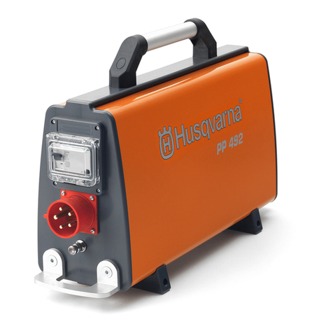
Husqvarna PP490 User manual