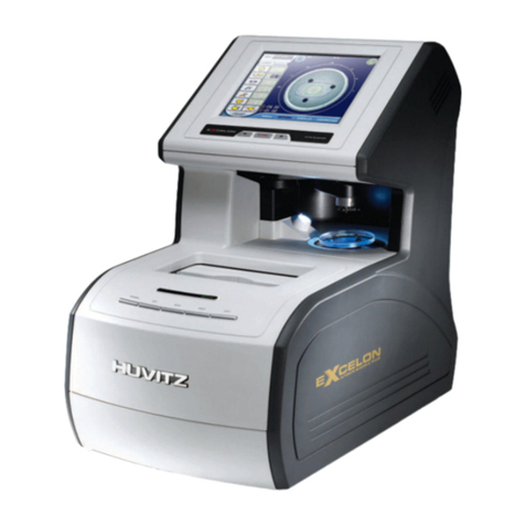
Huvitz Excelon User manual

EXCELON
Service manual
Huvitz

EXCELON
Contents
I. Troubleshooting Manual
1. Precaution for Safety………………………………………………………………………………………………2
2. Precaution for Installation…………………………………………………………………………………………2
3. Malfunction during Power UP……………………………………………………………………………………..3
4. Malfunction at Display……………………………………………………………………………………………..4
5. Malfunction at Frame Reader…………………………………………………………………………………….5
6. Malfunction during edging…………………………………………………………………………………………7
II. Edging Body Maintenance Manual
1. LCD Monitor Replacement………………………………………………………………………………………10
2. LCD Key Board Replacement……………………………………………………………..……………………12
3. Spindle Ass’y Bearing Replacement………………………………………………….…….…………………..13
4. Clamp Screw & Nut Replacement……………………………………………………………………….……..17
5. Feeler Ass’y Replacement……………………………………………………………………………………….20
6. Feller Ass’y X Lever Spring Replacement……………………………………………………………………..23
7. SBG Ass’y Replacement……………………………………………………………………………………….24
8. SBG Ass’y Ball Plunger Switch Replacement…………………………………………………………………25
9. Rotation Worm & Worm Wheel Replacement………………………………………………………………...26
10. Y-axis Screww & Nut Replacement……………………………………………………………………….…..28
11. Edging Room Shaft Bush Replacement……………………………………………………………………...32
12. Replacement and Maintenance of the cunsumer……………………………………………………………34
1. Grinding Wheel Replacement…………………………………………………………………………….34
2. SBG Wheel Replacement………………………………………………………………………..………36
3. Feeler Tip Replacement…………………………………………………………………………………..37
4. Block Adapter and Lens Clamp Replacement……………………………………………………….....38
5. Maintenance ; Injection of the grease…. ………………………………………………..……………...39
III. Frame Reader Maintenance Manual
1. Main Board Replacement ………………………………………………………………………….……………43
2. LCD & Button Board Replacement…………………………………………………………………..…………44
3. Gripping Wire & Spring Replacement…………………………………………………………………………..45
4. R-axis Rotation Cable Replacement…………………………………………………………………………...46
5. Big Gear Idler & Step Motor Gear Replacement………………………………………………………..…….47
6. X-axis Screw & Nut ………………………………………………………………………………………………49
7. R-axis Encoder & DC Motor Ass’y Replacement……………………………………………………………..50
8. Z-axis Encoder & DC Motor Ass’y Replacement………………………………………………….………….52
9. Stylus Tip Replacement…………………………………………………………………………………..……..53
IV. Blocker Maintenance Manual
1. Lamp Replacement ………………………………………………………………………………………………55
2. Window2 Guide1 Ass’y Spring Replacement………………………………………………………...………..56
3. Spreading grease on the Z-axis Shaft & Spring……………………………………………………………….57
4. Block Holder adjustment………………………………………………………………………..……………….58
V. Parts Price List…………………………………………………………………………………………….….59

EXCELON
Trouble shooting manual
I
-1
I. Troubleshooting Manual

EXCELON
Trouble shooting manual
I
-2
1. Precautions for Safety
1. Before/During Maintenance.
-Maintenance should be done by the service persons who are accustomed to using the instrument,
and have good technical knowledge.
-Be sure to turn the power off and remove the power cord from the electricity outlet during
maintenance. If not, it may cause severe electric shock.
-Be sure to follow the maintenance procedure. If not, it may cause another malfunctions, and more-
over fatal harm to the instrument.
-Do not drop parts or screws inside the instrument. It may cause fatal malfunctions.
-Use a proper tool during maintenance.
-When using grease be sure to refer to maintenance book to avoid misusing.
2. After Maintenance.
- Before turning on the power, be sure to check if the replaced parts are fixed securely to the right
place.
- In case of strange odors or smoke being emitted from the machine, turn OFF the machine
immediately and disconnect the power cord.
3. Cleaning.
- Do not spray water inside the machine. Only inside the edging room is allowed.
- Be careful when using grease. Be sure to check where to paste or where not to.
- Do not wipe out any covers with chemical solvents.
2. Precautions for Installation
1.Be sure to check if the locking brackets are removed.
2.Be sure to check if the power output is suitable and stable.
3.Be sure to set the machine on a leveled place or table.
4. Never run the machine with the Main cover open.

EXCELON
Trouble shooting manual
I
-3
3. Malfunction during Power UP
3.1 System is not on.
No
Yes
Yes
No
No
Yes
No
Yes
Is the power supplied
properly from the outlet?
(Check the system voltage)
Try another outlet.
Is the fuse blown? Replace the fuses.
Is the input voltage to the
SMPS proper?
Check the inlet
connection.
Is the output voltage from the
SMPS proper?
Replace the SMPS.
Check the connection
between SMPS & Main Board.

EXCELON
Trouble shooting manual
I
-4
4. Malfunction at Display
4.1 LCD is not on.
4.2 Screen freezes.
Yes
Is the system on?
No
Check the power.
Refer to 3.
Yes
Is the cable between Main
board and GUI board
disconnected?
Yes
Connect again
firmly.
No
Is the yellow LED flickering
on GUI board?
No
Replace the GUI
board.
Yes
Replace the LCD.
Refer to page 10.
Is the yellow LED flickering
on GUI board?
No
Replace the GUI
board.
Yes
Is the Software version
proper?
No
Upgrade the
Software version
to the latest.
Check the cable connection
between GUI board & Main
board.

EXCELON
Trouble shooting manual
I
-5
5. Malfunction at Frame Reader
5.1 Stylus goes up and is stuck. Sometimes repeats up-down and then, stops.
5.2 Frame shapes are significantly different or distorted.
5.2.1 Perform maintenance referring to 5.1
5.2.2 Perform Frame & Pattern Calibration.
5.3 Strange noise from the inside of the Frame Reader.
Stylus doesn’t move to the left or right and starts reading at wrong position.
Yes
No
Is the 14-Pin cable damaged?
Yes
Replace the 14-pin cable.
Refer to Maintenance book.
No
Is the 20-Pin flat cable
damaged?
Yes
Replace the 20-pin flat cable.
Is there anything on the
stylus cover?
Yes
Remove it and try again.
No
Is the Frame Reader fell down
or shocked?
Yes
Adjust X-moving Ass
’
y referring
to Maintenance book.
Is the room temperature
under 10
º
C or the Frame
Reader had been in cold
atmosphere for a long time?
Warm the room temperature at least more
than 10
º
C and try again.

EXCELON
Trouble shooting manual
I
-6
5.4 Stylus falls off a frame during reading.
5.5 After reading frame, “transmitting” message appears, but the data isn’t transmitted to the edging
body.
Yes
No
Is the R-direction movement
smooth?
No
Clean the slide with compressed
air or adjust R-Motor Ass
’
ygap
referring to page 15.
Yes
Is the Z-direction movement
smooth?
No
Adjust Frame force or set
value.
Yes
Clean the slide with compressed
air or adjust Z Updown Ass’y gap
referring to Maintenance book.
Is the cable connected
properly?
No
Connect again to the proper port.
Yes
Is the cable broken?
No
Is the port Configuration
correct?
Yes
Replace the RS-232C cable.
Set the port Configuration properly.
Replace the Main Board of
Frame Reader referring to
page 43

EXCELON
Trouble shooting manual
I
-7
6. Malfunction during edging
6.1 Feeler doesn’t move down.
Check the feeler PI position and adjust the backlash of between Rotate Worm and Worm wheel Ass’y.
6.2 Feeler doesn’t contact with lens.
6.3 Wheel doesn’t rotate.
Check the Inverter cable.
6.4 Water doesn’t come out.
Is there any dust or leftover on
the surface of the feeler shaft?
Yes
Remove them.
No
Is the pressure between Encoder
pinion and the Rack too tight?
Yes
No
Adjust the gap.
Replace the Feeler Ass
’
y.
Is the pump cable
disconnected?
Yes
Connect again.
No
Are the voltage and the Pump
specification proper?
No
Yes
Replace the Pump with
a proper one.
Is the SSR blown?
(when the pump operates,
is the LED on SSR off?)
Yes
Replace the SSR
No
Replace the Edger Main Board.

EXCELON
Trouble shooting manual
I
-8
6.5 Bevel & Groove position varies oftenly.
Check the Feeler Ass’y referring to 6.2.
6.6 Sometimes lens size error between left and right occurs.
6.7 Bevel is rounded off.
6.8 Grinding takes too much time.
6.9 Lens axis shifted.
Use proper blocks, proper tapes and choose proper Edging Option.
No
Yes
Is the size correct after
calibration?
Yes
Is the Software of the Frame
Reader upgraded to the latest?
No
Adjust Y-Axis Nut & Screw.
If necessary, replace them referring to
page 28.
Replace the Frame Reader.
Upgrade the Software to the
latest version.
Is the contact switch cable
disconnected?
Yes
Connect again.
No
Is the surface of the Contact
switch clean?
No
Yes
Clean them.
Replace the wheels
Refer to 6.7
Is the Bevel proper, after dressing wheel? Replace the wheel
No

II. Edging Body Maintenance Manual

EXCELON
CPE-4000 Maintenance
Ⅱ
-
10
1. LCD Monitor Replacement
1. Open the Main Cover.
2. Remove the protection plastic cover of the LCDAss’y.
3. Disconnect the four connectors linked to the GUI Board.
4. Remove all screws that are shown in below picture and Separate the LCDAss’y.
5. Separate the LCD Window from the LCD Ass’y.
6. Disconnect all connectors.
7. Separate the GUI Board.
Step 4
Ten-Key B/D Connector
Right-Key B/D Connector
LCD TO IJ13 ConnectorPower Connector
Step 3
Step 1
Edger Cover
LCD Window
Step 5

EXCELON
CPE-4000 Maintenance
Ⅱ
-
11
8. Replace LCD with a new one.
9. Assemble all removed parts in reverse order.
Caution
Be careful with the surface of LCD.
Adjustment needed
None
Step 6
Step 7
LCD Monitor Inverter
Step 8

EXCELON
CPE-4000 Maintenance
Ⅱ
-
12
2. LCD Key Board Replacement
1. Separate the LCDAss’y from the Main Cover.
2. Remove the front acryl window and Separate wrong Key Board.
3. Replace it with a new one.
4. Assemble all parts in reverse order.
Caution
Be sure to check whether every key function is right or not.
Adjustment needed
LCD Key B/D
8-Ke
y
LCD Key B/D
6-Ke
y
Step 2
Ste
p
3
LCD Key B/D
8-Ke
y
LCD Key B/D
6-Ke
y

EXCELON
CPE-4000 Maintenance
Ⅱ
-
13
3. Spindle Ass’y Bearing Replacement
1. Open the Main Cover.
2. Remove the Edger right cover.
3. Remove the Edging room window Ass’y.
4. Remove the four Grinding Wheels and the Shaft Water Cover.
Refer to [12-1 Grinding Wheel Replacement] section.
5. Remove the two Spindle holders.
6. Loosen the Tension control screw from Base Motor Pusher and loosen locking screws of the Motor
Bracket.
7. Remove the Belt.
8. Separate the Spindle Ass’y from the Edging room.
9. Remove locking screw of the right side of the Spindle Ass’y with adequate tools.
Step 5
M6 tension control screw
Step 6
Belt
Edging Room Window Ass’y
Step 3
Shaft Water Cover
Step 4

EXCELON
CPE-4000 Maintenance
Ⅱ
-
14
10. Remove the Right Shaft Plug, Shaft Small Pulley and Key.
11. Remove the Right Shaft Cover with adequate tool.
12. Remove the O-ring and Shaft Water Cover Spacer.
13. Remove the two V-rings.
14. Remove the Left Shaft Cover with tool.
Spindle Ass’y Step 9
M6 screw
Right Shaft Plug
Shaft Small Pulley
Step 10
Key
Step 11
Left Shaft Cover
V-ring
Shaft Water Cover Spacer
O-ring
Step 12,13,14
JIG

EXCELON
CPE-4000 Maintenance
Ⅱ
-
15
15. Separate ball bearings from both side of the Shaft Housing.
Be sure to remember the insertion direction of the Disk Springs when extracting the right side
bearing.
16. Replace them with new ones (6004ZZ).
17. Assemble the Right Shaft cover.
18. Assemble the Left Shaft cover.
19. Insert V-rings. (If necessary, replace it with a new one)
20. Insert the Shaft water cover spacer.
Be sure to spread mechanical grease between V-ring and Shaft water cover spacer.
21. Insert O-ring into the Spindle Shaft Main.
The O-ring should be squeezed into the Shaft water cover spacer.
22. Assemble all parts in reverse order.
23. Assemble SpindleAss’y in reverse order. Be sure to fit the position with location pin.
BearingDisk Spring
Bearing
Step 15
Shaft Water Cover Spacer
Step 21
Shaft Water Cover Spacer
Step 20
Spread grease
on this surface
A
ssembled Disk Spring

EXCELON
CPE-4000 Maintenance
Ⅱ
-
16
24. Fit the Edging room and V-ring like below picture.
If necessary, spread some waterproof grease or something.
25. Assemble SpindleAss’y holder in reverse order.
Be sure to check whether the Spindle Ass’y moves or not.
26. Assemble the Belt in reverse order and fit the belt tension between 90~100Hz or the deflection
amount between 7 ~ 10mm when pressed in the middle of the belt.
27. Assemble wheels in reverse order.
Refer to [12-1 Grinding Wheel Replacement].
28. Assemble covers in reverse order.
Caution
Do not change the direction of the Disk Spring. (Step 15)
There should be no water leakage.(Step 25)
Adjustment needed
Check whether the Wheel Ass’y works right in the Test Mode.
After performing Size Calibration, check the Bevel Adjustment.
If Bevel Adjustment value is changed, check the Size Adjustment.
If there’s large amount of vibration or noise, adjust belt tension or wheel balance again.
Pin
Base Plate Support 4
Step 23
V-ring
Edging Room
Step 24

EXCELON
CPE-4000 Maintenance
Ⅱ
-
17
4. Clamp Screw & Nut Replacement
1. Open the Main Cover and right side cover.
2. Remove the Edging room window.
3. Remove the Lens Clamp.
4. Loosen two setscrews from the Chuck Screw Plate and separate the Chuck Screw Plate from the
Chuck Moving Screw.
5. Loosen the three locking screws of the Motor bracket.
Remove the Belt.
6. Remove the Chuck right cover.
7. Extract the Chuck Moving Pulley slowly.
The Chuck Moving Screw, the Chuck Moving Pulley and the Chuck Shaft are linked each other.
Step 3 Lens Clamp
M5 setscrew
Chuck Right Cover
(Step 7)
Motor
(Step 6)
Step 5, 6
Chuck Moving Screw
Chuck Screw Plate
Step 5

EXCELON
CPE-4000 Maintenance
Ⅱ
-
18
8. Separate the Chuck Moving Screw from the Chuck moving pulley.
9. Replace the new Chuck moving pulley ass’y.
10. If necessary replace the steel ball with new one and spread mechanical grease enough.
11. If the Chuck Shaft Pivot is damaged, replace with new Chuck Shaft and new Chuck Shaft Pivot.
12. Spread the grease around the key of the Chuck Shaft.
13. Assemble the two Disk Springs like below picture.
14. Assemble the Chuck moving pulley and Chuck shaft in reverse order. Be sure to hook Chuck Shaft
Pivot with Chuck Moving Screw. Refer to below picture.
Chuck Shaft
Chuck Moving Screw
Chuck Moving Pulley
Step 8
Steel Ball
Step 9
Disk Spring
Step 13
Key groove
Step 13
Chuck Shaft
Chuck Shaft Pivot
Rotation Right Pulley
A
ssembled Disk Spring
Other manuals for Excelon
1
Table of contents
Other Huvitz Laboratory Equipment manuals

Huvitz
Huvitz CME-9000 User manual

Huvitz
Huvitz HNT-7000 User manual

Huvitz
Huvitz HNT-1 Operating instructions

Huvitz
Huvitz Excelon XD User manual

Huvitz
Huvitz HS-5000 User manual

Huvitz
Huvitz SMART BLOCKER HBK-410 User manual

Huvitz
Huvitz Excelon CAB-4000 User manual

Huvitz
Huvitz CRK-7000 User manual

Huvitz
Huvitz HRK-7000 User manual

Huvitz
Huvitz HLM-9000 User manual