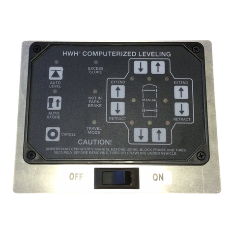
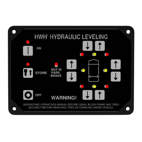
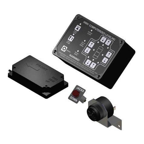
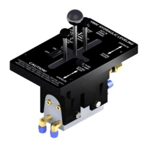
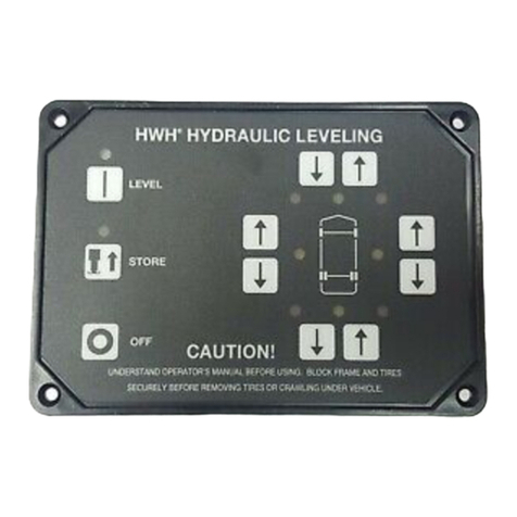
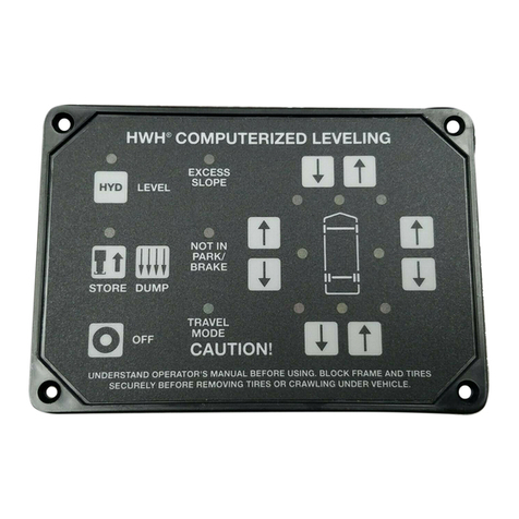
HWH 200 series User manual

H
CORPORATION
H
W
R
HWH CORPORATION
2096 MOSCOW ROAD
MOSCOW, IOWA 52760
(800) 321-3494 / (563) 724-3396
INTERNET: http: //www.hwhcorp.com
INSTALLATION MANUAL
HWH HYDRAULIC LEVELING
UNDERSTAND OPERATOR’S MANUAL BEFORE USING. BLOCK FRAME AND TIRES
SECURELY BEFORE REMOVING TIRES OR CRAWLING UNDER VEHICLE.
OFF CAUTION!
ON
5 AMP
FUSE
FUSE
NOT IN
PARK/
BRAKE
EXTEND
RIGHT
HWH HYDRAULIC LEVELING
"CAUTION"
REMOVING TIRES OR CRAWLING UNDER VEHICLE.
BLOCK FRAME AND TIRES SECURELY BEFORE
UNDERSTAND OPERATOR’S MANUAL BEFORE USING.
REAR
FRONT
LEFT
EXTEND
EXTEND
EXTEND
OPERATE
STORE
REAR
FRONT
STORE
OPERATE
HWH JOY STICK-CONTROLLED
LEVELING SYSTEM
200 SERIES
FOR MOTORHOMES
19MAR01
ML10897/MI35.0006
(ON I-80, EXIT 267 SOUTH)

HWH HYDRAULIC LEVELING JACKS
MI35.0505
21JUN95
INSTALLATION MANUAL
ON MOTOR HOMES
THE FOLLOWING INSTALLATION INFORMATION IS OFFERED AS SUGGESTIONS ONLY. VARIATIONS IN VEHICLE
DESIGN, CHASSIS, SUSPENSIONS,TIRES AND COACH WEIGHTS MAKE IT IMPOSSIBLE TO ANTICIPATE AND ADDRESS
ALL INSTALLATION PROBLEMS AND POSSIBILITIES. SOME VEHICLE BUILDERS OR CHASSIS BUILDERS MAY USE
PRACTICES DIFFERENT FROM THOSE IN THIS MANUAL. CONSULT HWH CORPORATION OR THE VEHICLE BUILDER
FOR INFORMATION CONCERNING CORRECT SYSTEM CAPACITY AND TYPE FOR THE VEHICLE, INSTALLATION
QUESTIONS, AND INSTALLATION OF OTHER HWH EQUIPMENT.
ONLY QUALIFIED TECHNICIANS SHOULD INSTALL OR REPAIR LEVELING SYSTEMS ON VEHICLES. A KNOWLEDGE OF
HYDRAULICS, WELDING, THE VEHICLE’S SUSPENSION AND ELECTRICAL SYSTEM, AS WELL AS AN UNDERSTAND-
ING OF THE LEVELING SYSTEM’S HYDRAULICS AND ELECTRONICS IS REQUIRED.
damages or injuries resulting from the
NOTE - HWH Corporation assumes no liability for
installation of this product.
CAUTION !
READ THE ENTIRE INSTALLATION PROCEDURE BEFORE STARTING INSTALLATION.
BLOCK FRAME AND TIRES BEFORE CRAWLING UNDER VEHICLE. DO NOT USE LEVELING JACKS OR AIR
SUSPENSION TO SUPPORT VEHICLE WHILE UNDER VEHICLE OR CHANGING TIRES. VEHICLE MAY DROP AND/
OR MOVE FORWARD OR BACKWARD WITHOUT WARNING CAUSING INJURY OR DEATH.
DO NOT TURN ON POWER UNTIL INSTALLATION IS COMPLETE.
WHEN ROUTING HYDRAULIC HOSES AND WIRES, BE SURE THEY ARE NOT EXPOSED TO ENGINE EXHAUST OR
ANY HIGH TEMPERATURE COMPONENTS OF THE VEHICLE.
KICKDOWN JACKS MAY ABRUPTLY SWING UP WHEN THE FOOT CLEARS THE GROUND OR WHEN JACK REACHES
FULL EXTENSION.
NEVER PLACE HANDS OR OTHER PARTS OF THE BODY NEAR HYDRAULIC LEAKS. OIL MAY PENETRATE THE SKIN
CAUSING INJURY OR DEATH.
SAFETY GLASSES ARE TO BE WORN TO PROTECT EYES FROM DIRT, METAL CHIPS, OIL LEAKS, ETC. FOLLOW
ALL OTHER APPLICABLE SHOP SAFETY PRACTICES.
DO NOT OVER EXTEND THE REAR JACKS. IF THE WEIGHT OF THE VEHICLE IS REMOVED FROM ONE OR BOTH
REAR WHEELS, THE VEHICLE MAY ROLL FORWARD OR BACKWARD OFF THE JACKS.

PRE-INSTALLATION CHECKS
MI35.1005
23AUG95
THESE ARE ITEMS THE INSTALLER SHOULD CHECK BEFORE STARTING THE INSTALLATION:
Do the jacks have the proper capacity for the axle weights of the vehicle?
Do the jacks have the proper stroke for the mounting heights available?
Does the pump have the proper reservoir capacity for the jacks being used?
Are acceptable mounting locations available for the jacks and other system components?
Will the mounting brackets or jacks interfere with any vehicle components or structure?
If the vehicle is equipped with a full air-bag suspension an air dump system must be used
Vehicles with supplemental air bags or suspensions such as JET AIR do not
Are all components necessary for the installation, including mounting brackets, hardware kits,
Does the vehicle need exhaust work done before the jacks are installed?
Does the vehicle have a good set of batteries that are fully charged?
IF THERE ARE ANY PROBLEMS WITH ANY OF THE ABOVE ITEMS, CONTACT HWH CORPORATION BEFORE STARTING
THE INSTALLATION
for proper leveling.
have to dump the air from the bags.
hoses, etc. present?
PART I
NOTE :
1.)
2.)
3.)
4.)
5.)
6.)
7.)
8.)
9.)
NOTE: Do not use kickdown style jacks and straight acting jacks on the same vehicle.

PART II
MI35.1505
11JAN96
LOCATING THE JACKS
mounting bracket for the flanges of the frame rail, is important.
widest possibe pattern. Always bolt at the top and bottom of the
frame rail whether using mounting brackets, or bolting straight
acting jacks directly to the frame rail.
HWH Corporation does not suggest welding brackets or
straight acting jacks to the frame rails. Do NOT weld kick down
jacks to the mounting brackets or directly to the frame rail.
(See Section B-WELDING) If it is necessary to modify the tail-
will reduce stress in the vehicle and leveling system. When a
tag axle is used the jacks should be mounted between the drive
axle and the tag axle. Mounting the front jacks in front of the
ation or the coach manufacturer before mounting the front jacks
in front of the front axle.
up towards the rear of the vehicle when retracted. Mounting
gested. Mounting jacks that will fold toward the front as in FIG-
URE 3 is unacceptable.
3. JACK MOUNTING HEIGHT:
ing heights or locations refer to the Clearance and Mounting
Dimensions Charts. Combining these dimensions and in-
formation supplied on the "JACK BRACKET" sheets (See
"BRACKETS"-HWH Service Manual) will make it possible to
figure proper mounting heights and locations before starting
the installation. In most cases these mounting heights will
provide clearance on uneven terrain and permit the placement
of a pad under the jacks when operating on soft ground or
asphalt. (Pads are available from HWH Corporation)
shown on the Dimension Charts apply to vehicles with a full
load of fuel, water and equipment. When empty add 1" to
these dimensions. Also take into consideration that new ve-
hicles can settle down 3/4" or more during the first year or
initial 10,000 miles.
suggests using straight acting jacks on vehicles with full air
bag suspension. The vehicle should be at the proper ride
height when determining the proper mounting heights for
the jacks. If kick down style jacks are used, add 2 inches to
the suggested jack mounting heights.
CAUTION:
VEHICLE WILL RAPIDLY DROP SEV-
ERAL INCHES IF AIR BAGS DEFLATE.
DEFLATE AIR BAGS BEFORE WORK-
ING UNDER THE VEHICLE.
4. DEFLATING AIR BAGS:
the vehicle’s frame must be securely blocked. The air can
be released by disconnecting the air line between the height
control valve and the air bag. Usually the fitting at the height
control valve is easiest to get to. (See the SUSPENSION AIR
DUMP DIAGRAM)
IMPORTANT:
quickly. Make sure there is adequate clearance to work under
the coach.
SWING TO REAR
IDEAL
FIGURE 1 FIGURE 2
SWING TO REAR
NOT SUGGESTED FIGURE 3
SWING FORWARD
UNACCEPTABLE FIGURE 4
SWING SIDEWAYS
NOT SUGGESTED
2. MOUNTING ARRANGEMENT:
tion for the jacks is important for the proper functioning of the
When the air is released the bags will deflate
pipe, have the owner take the vehicle to a professional muffler
shop for proper procedure before starting installation.
Most brackets are designed with specific bolt hole arrangements.
Use of all holes, especially holes used for the fingers of the
possible behind the front and rear axles. (See FIGURE 1) This
axle is not suggested. (See FIGURE 2) Contact HWH Corpor-
Vehicles with spring suspension:
The ground clearance
Vehicles with full air bag suspensions:
JACK INSTALLATION
1. MOUNTING BRACKETS:
HWH Corporation has bolt-on
mounting brackets available for many different applications.
(See "BRACKETS"-HWH Service Manual) Most of the brack-
ets are designed to fit a specific chassis in a specific location.
Slight modification of these brackets is acceptable but HWH
Corporation should be contacted when modifying or changing
the mounting locations of these brackets. The kick down brack-
ets are designed for use with 6000# and 9000# jacks. Many
vehicles requiring 16000# jacks are equipped with mounting
brackets for these jacks. Contact HWH Corporation for mount-
The correct mounting loca-
When figuring proper mount-
Before deflating the air bags
When using brackets with multiple sets of bolt holes, use the
the jacks in other positions as shown in FIGURE 4 is not sug-
ing information when needed.
HWH Corporation
leveling system. The jacks should be mounted as close as
Kick down style jacks must be mounted so that they swing

PART II
MI35.1510
08FEB96
4. MOUNTING LOCATIONS
JACK INSTALLATION
: Refer to the CLEARANCE AND
MOUNTING DIMENSIONS CHARTS for specific measure-
ments.
Some general mounting location suggestions are:
2.) Do not mount rear jacks on frame extensions.
3.) Jacks should be mounted near frame cross members.
4.) When frame cross members are not close the jack brackets
should be tied together with a cross member.
5.) Front or rear jacks may be staggered several inches to ac-
commodate vehicle equipment and compartments.
6.) Front jacks and mounting brackets must be mounted so
they do not interfere with suspension components when re-
tracted or extended.
IMPORTANT:
Clearance MUST be provided for kick down
front of vehicles with a raised rail chassis such as Spartans
must be tied together. If using straight acting jacks, it is sug-
Be sure jacks, jack mountings, or mounting brackets do not
interfere with any moving components on the vehicle such as
axles, springs, air bags, steering linkage, etc. Kick down jacks
may need to be adjusted to allow full extension of the jack in
the horizontal position.
HWH Corporation assumes no liability for damages to the
vehicle or jack resulting from jack extension in the horizon-
tal position.
Jacks must NOT be exposed to high temperatures such as
exhaust pipes. If exhaust pipes need to be moved, this should
be done before installing the leveling system. Heat shields
supplied with HWH brackets should be applied to both sides.
After-market exhaust systems may be added at a later date
exposing jacks to high temperatures.
NOTE:
7.) Front jacks and mounting brackets must be mounted so
they do not interfere with tires when turned stop to stop.
gested the front jacks on all installations be tied together when
possible.
1.) Rear jacks should always be mounted behind the drive axle.
When using straight acting jacks, the rear jacks on all
installations must be tied together. Straight acting jacks on the
jacks to extend fully in the horizontal position to prevent se-
rious damage to the vehicle.

MI35.1515
05SEP96
CLEARANCE AND MOUNTING DIMENSION CHART
JACK RETRACTED
DIMENSIONS
A B C
EXTENDED
DIMENSIONS
FEDIHGJK
STROKE MOUNTING
WIDTH MOUNTING BOLT
PATTERN
6000#
SHORT 12.5" 4.5" 12.0" MIN
14.0"
MAX
16.0"
19.0" MIN
2.0"
MAX
4.0"
7.0" 6.5" 1.5" 4.5"
6000#
TALL
19.5"
9000#
SHORT
9000#
TALL
16000#
14.0" 22.0"
14.5" 23.0"
15.5" 24.5"
18.0" 26.0"
4.5" 13.5"
6.5" 13.5"
6.5" 14.5"
7.0" 16.75"
MIN
15.5"
MAX
17.5"
21.5" MIN
2.0"
MAX
4.0"
MIN
16.5"
MAX
18.0"
22.0" MIN
3.0"
MAX
4.5"
MIN
17.5"
MAX
19.0"
23.5" MIN
3.0"
MAX
4.5"
MIN
19.75"
MAX
21.25"
24.75" MIN
3.0"
MAX
4.5"
8.0" 6.5"
8.5" 8.5"
9.0" 8.5"
8.0" 12.5"
1.5" 4.5"
1.5" 4.5"
1.5" 4.5"
4.0" 4.0"
Dimension E is the suggested mounting height.
Dimension G is the suggested ground clearance when the jack is vertical but not extended.
* If using kick - down jacks on vehicles with full airbag suspensions, add 2 inches to this dimension.
K
J
D
E
F
G
I
A
B
C
KICK - DOWN JACKS
SIDE VIEW TOP VIEW
DIMENSION "I" INCLUDES SPRINGS.
GROUND
LINE
PART II
H

MI35.1520
25AUG95
CLEARANCE AND MOUNTING DIMENSION CHART
JACK MOUNTING WIDTH
A B
GROUND
CLEARANCE E
STROKE RETRACTED
HEIGHT BRACKET
HEIGHT
AP0468**
FORD OSKOSH-X 8.0" 19.5"
A-P1197**
6000# X 13"
AP1152
6000# X 16"
9000# x 13"
9.5"
12.0"
STRAIGHT ACTING JACKS
FRONT VIEW SIDE VIEW
GROUND
LINE
TOP
CLEARANCE
FGH
CALL HWH CORPORATION
AP2025
CHEVY P-30 FRONT
AP2026
FRONT
AP10466**
CHEVY & FORD
REAR ONLY
AP9551**
AP0154
9000# x 16"
AP9552**
12000# X 13"
AP9809
12000# X 16"
AP9553**
16000# X 13"
AP9823
16000# X 16"
8.0"
9.4"
4.9"
6.0"
6.0"
4.9"
4.9"
8.0"
9.4" 6.0"
9.4" 6.0"
9.4" 6.0"
7.0"
12.0" 7.0"
8.0" MIN
10.0" MAX
8.0" MIN
10.0" MAX
8.0" MIN
10.0" MAX
8.0" MIN
10.0" MAX
8.0" MIN
10.0" MAX
8.0" MIN
10.0" MAX
8.0" MIN
10.0" MAX
8.0" MIN
10.0" MAX
8.0" MIN
10.0" MAX
13.0"
13.0"
13.0"
13.0"
13.0"
13.0"
16.0"
16.0"
16.0"
16.0"
22.5"
22.5"
20.0"
21.7"
25.8"
21.9"
25.9
22.0"
28.5"
21.0"
23.5"
17.0"
17.0"
21.0"
17.0"
17.3"
17.5"
17.5"
14.5"
0.0"
0.0"
1.6"
0.8"
0.0"
0.0"
0.0"
0.5"
0.0"
0.5"
C *
A
C
BH
G
F
E
PART II
* Take into account clearance for other coach equipment when determining mounting heights.
** When mounting 13" stroke jacks on coaches with spring suspensions, using 8.0" of ground clearance.
8.0" MIN
10.0" MAX

JACK INSTALLATION
MI35.1525
06JAN96
WELDING
1. G.M.
Disconnect both battery cables. ALWAYS DISCONNECT
THE GROUND CABLE FIRST.
Disconnect computer module wiring.
Attach the welding ground to the part to be welded.
Do not use suspension components as ground points.
Keep welding cables away from electrical systems.
2. FORD
Disconnect both battery cables. ALWAYS DISCONNECT
THE GROUND CABLE FIRST.
Disconnect computer module wiring.
Attach the welding ground to the part to be welded.
Do not use suspension components as ground points.
Keep welding cables away from electrical systems.
3. OSH KOSH
Disconnect both battery cables. ALWAYS DISCONNECT
THE GROUND CABLE FIRST.
Attach the welding ground to the part to be welded.
Do not use suspension components as ground points.
Keep welding cables away from electrical systems.
4. GILLIG
Disconnect both battery cables. ALWAYS DISCONNECT
THE GROUND CABLE FIRST.
Attach the welding ground to the part to be welded.
Do not use suspension components as ground points.
Keep welding cables away from electrical systems.
5. SPARTAN
Disconnect both battery cables. ALWAYS DISCONNECT
THE GROUND CABLE FIRST.
Attach the welding ground to the part to be welded.
Do not use suspension components as ground points.
Keep welding cables away from electrical systems.
HWH Corporation does not suggest welding brackets to the frame rails. However, if any welding is done such as modifying a
jack bracket already mounted, the following precautions should be observed:
Connect welding ground to part being welded. NEVER weld to suspension parts such as spring shackles. NEVER weld across
the bottom flange of the frame rail. Brackets should be located near a cross member. For additional information on the vehicle,
Check with the chassis manufacturer for the most
recent information on welding precautions.
NOTE:
PART II
chassis, brackets, and mounting location, contact the vehicle’s builder, the chassis or suspension supplier, or HWH Corporation.
IMPORTANT:
There may be fuel lines or wire inside the frame rail. They should be well protected from the heat caused by weld-
ing. Damage or personal injury could occur. The following are welding precautions for specific chassis manufactures:

COMPONENT INSTALLATION
MI35.2006
15JAN01
If the valve is to be put near the left front tire, care
should be taken to keep it as far outboard and rearward as
possible. If mounted too close to the tire, the valve may be
struck by the tire on rough or bumpy roads or when turning.
2. MOUNTING THE VALVE
1. LOCATING THE VALVE:
the left of the driver’s seat. This location is not vital but is most
convenient. If the need arises the valve can be put elsewhere
such as alongside the couch or chair. Be sure to check under-
neath to see that the bottom of the valve will be accessible
It is not advisable to put the valve in a compartment or in the
dash.
The joystick (200 Series) light panel may be flush mounted in
a flat surface such as the dash or may be surface mounted
on the floor or other convenient locations by using the 1.75"
tall spacer box. When surface mounting the light panel ad-
jacent to the valve be sure to orientate the panel so the yellow
lights coincide with the coach. Drill a 1" hole beneath the light
panel to pass the wiring through. Do not mount the light panel
until all wiring is complete. Always leave enough wire length
in the spacer box to allow lifting the panel for repair. Be sure
to seal the 1" hole when finished. Never flush mount a panel
in the floor. The panel must always be protected from dirt and
and water. When flush mounting the light panel, a rectangular
hole with 45 degree corners matching the back of the panel
will need to be cut in the mounting surface.( See Template at
the end of Part III.) There must be a minimum clearance of 2"
behind the mounting surface to allow for the panel and the
from the top. Secure valve and cover plate at the same time
using four #10 x 3/4" Phillips head screws. Caulk around the
underside of the valve where the box meets the floor.
3. LOCATING AND MOUNTING THE PUMP:
4. HYDRAULIC HOSES
Do not attach hoses or wiring to any fuel
CAUTION:
When connecting hoses and wiring harnesses to the
kick down jacks always check that the jack can swing from the
horizontal position to a position 45 degrees beyond the ver-
tical position, without kinking the hose or without tight wires.
The jack must also be able to freely fold back to its stored
position.
Straight Acting Jacks:
wiring harnesses must have enough slack to allow free move-
ment of the jack.
There are different lengths of hoses to be routed to the four
leveling jacks. (Refer to the Hydraulic Hookup Diagram)
Straight Acting Jacks:
and connect it to the hose fitting. 90 degree swivel fittings are
available if needed for clearance.
IMPORTANT:
A LEAKING HOSE CAN POSE A FIRE HAZARD.
A KICK DOWN JACK WILL
SWING UP ABRUPTLY WHEN IT IS RELEASED.
EXTREME
CAUTION:
PART III
Can pivot several inches. Hoses and
Route the hose to the top of the jacks
The valve is normally placed to
:
not always possible, it is desirable to put the pump assembly
under the hood compartment where it is easily accessible for
service or fluid check and refill. The distance of the pump from
the valve is limited by the 7’ hose provided and the battery
cable although a longer hose and cable may be used if available.
: It is important to keep the ends of
the hoses plugged during installation to prevent any dirt from
entering the system. Hoses should be routed away from any
heat emitting items such as engine or exhaust components.
A good location is along the outside of the frame rail. It may
be necessary to build a heat shield and/or adequately insul-
ate the hoses. Care should be taken to avoid sharp edges.
NOTE:
NOTE:
The pump and pump relay should be protected from direct
NOTE:
Do not remove fitting caps until attaching the hose
to the valve.
The joystick valve (200 Series)
requires a 3.25 inch by 7.00 inch hole cut at the desired lo-
cation. The valve should be mounted so that the front and the
aft movement of the control lever is in line with the coach.
Be sure there is adequate clearance for full movement of
all levers. Before cutting the hole, be sure to check underneath
road dirt.
wiring.
The joystick valve (200 Series) will drop through the hole
Although it is
or brake lines. Do not run hoses across the transmission
crossmembers on front control coaches.
for wiring, structural parts, or other items that may create a prob-
lem. Also be sure to leave enough room to connect all hy-
draulic hoses. existing hose end, tighten the hose end to snug plus 1/4
tighten the hose end 1/3 turn (2 FLATS). If tightening an
make the hose end snug (finger tight) on the fitting, then
Tightening of hose ends: If tightening a new hose end,
turn (1 FLAT).

PART III
MI35.2010
21JUN95
KICK DOWN JACKS:
A short hose is attached to the
jack at the factory. The hose is clamped to the pivot bracket.
It can be moved to the opposite side of the jack if necessary
to avoid heat sources or other obstacles.
ROLLER
BEARING
9000# KICK DOWN JACK
jack, the hose should go in the upper left-hand corner, over
the pivot area and down the front of the jack. After connect-
ing the hose to the fitting, the hose should be clamped with
a 1/4" bolt to the left side of the pivot bracket. Be sure the
hose is snug against the jack in the retracted (horizontal)
position.
Route the hose around the left
pivot, then across the back side of the cylinder and connect
to the actuator fitting. Attach the hose to the pivot bracket
using a hose clamp. There should be no slack in the hose.
- When connecting the hose to the
COMPONENT INSTALLATION
6000# KICK DOWN JACK- 16000# KICK DOWN JACK-
FIGURE 5
FIGURE 6
FIGURE 7

PART III
MI35.2012
18SEP95
5. WIRING:
Refer to the appropriate electrical diagram for
wiring. Any wire or cable in the interior of the coach is to be
protected by fusing. All wire insulation should be rated 125
deg. Celsius (257 deg. F). Check applicable RVIA or other
code for detailed fusing and wiring information. Protecting
all wires and cables by fusing is desirable.
A #2 battery cable is supplied with most systems to connect
the pump to the battery or a battery junction post. If a different
cable is used it must be able to carry 200 amperes. If fusing
is required, use a 200 ampere fuse. The fuse should be placed
near the power source. Never connect a fuse directly to the
battery or place it in the battery box where an electrical spark
can cause the battery to explode. If power is taken directly
from the battery, the fuse should be at least 18" from the bat-
tery. A fuse kit is available from HWH Corporation.
Wiring harnesses supplied are usually adequate for most
installations. Harnesses are loomed at the factory. All con-
nections are plug in type except for pump relay which has
ring terminal connections and the power supply for the panel.
That is a field connection made by the installers.
If lengthening or shortening the harness is necessary it is
suggested that all connections be soldered and protected
with shrink tube. If other connection devices are used they
must be sealed to prevent deteriation of the connection.
Grease-filled weather resistant crimp on butt connectors are
available .
Packard Connectors are marked with A & B for wire
connections. This cannot be mixed up. Maintain correct wire
size and color when altering harnesses.
Master Warning Light/Buzzer connections are done by the
installer. Route all wiring away from all heat sources and pro-
tect against sharp edges. Check that jacks can pivot properly
without cutting or stretching wire harnesses or connections.
All grounding connections are supplied by HWH Corporation
and all grounding should be done at the supplied ground stud.
(Refer to PUMP RELAY AND PANEL CONNECTION DIAGRAM).
Coat all exposed electrical connections (battery cable ends,
pump solenoid terminals, grounds, etc.) with a protective
sealant such as Kraylon 1307.
7. THE MASTER WARNING LIGHT/BUZZER:
Warning Light should be used with all systems. A buzzer must
be used with systems using straight acting jacks.The Master
Warning Light should be mounted in the dash in a location
highly visible to the driver. This light will warn the driver if
any of the jacks are down when the ignition is turned to "ON".
Drill a 1/2" hole at the desired location. Be sure to check for
wires or other devices behind the surface before drilling. When
installing the light itself, make sure the ignition is in the "OFF"
position. With the ignition on +12 can be present at the warn-
ing light.
When using a buzzer, the +12 power should come from the
"ON" side of the ignition switch. The power for the panel should
come from the "ACC" side of the ignition switch. (Refer to the
MASTER LIGHT/BUZZER CONNECTION DIAGRAM). With
all wiring complete, the light plate may now be mounted.
A Master
COMPONENT INSTALLATION
NOTE:
THE BLUE PARK BRAKE WIRE IS A
SAFETY FEATURE AND MUST BE HOOKED UP ACCORD-
ING TO THE WIRING DIAGRAMS.
IMPORTANT:
6. PARK BRAKE CONTROL WIRE:
The blue wire should
supply a ground signal or a +12 signal to the light panel only
when the park brake is applied. The blue wire is a single,
loomed wire in a separate plug at the light panel. The plug is
wired for a ground signal park brake switch.
GROUND SIGNAL PARK BRAKE:
The existing wire to the
park brake switch is cut and routed to the connectors on the
end of the blue park brake wire harness. The connectors are
labeled and must be connected accordingly for the system to
function properly. Protect the connections with the shink tube
that is supplied. Other wire terminals may be used on the end
of the harness but DO NOT eliminate the diode arrangement.
(See FIGURE 8)
TO PARK BRAKE
LIGHT
PARK BRAKE
SWITCH
BLUE WIRE TO
LIGHT PANEL
DIODE ARRANGEMENT
FIGURE 8
FIGURE 9
GROUND SIGNAL
ARRANGEMENT +12 SIGNAL
ARRANGEMENT
WHITE JUMPER
BLUE
PARK BRAKE
SWITCH WIRE
SHOWN WITH COVER REMOVED
+12 PARK BRAKE:
Eliminate the diode arrangemnent at the
end of the blue park brake wire. (FIGURE 8) Splice the blue
wire directly onto the wire from the park brake switch. Solder-
ing with shrink tube is the preferred way to make this connec-
tion. A different park brake harness may be ordered for +12
park brake installations or the original plug can be rewired
to work corrrectly. (See FIGURE 9)

PART III
MI35.2017
18SEP95
8. MOUNTING THE SENSING UNIT:
can be mounted above or below the surface as long as the
"This Side Up" sticker (FIGURE 10) is facing up and the "Rear"
arrow is pointing to the rear of the coach. The sensing unit
must be mounted to a solid surface that will not flex. Do NOT
mount the sensing unit near any heat-emitting items. Outside
of the frame rails is preferred. The sensing unit must be at
least 12" away from exhaust pipes or other high temperature
components, and must not be in line of sight from these high
temperature components.
9. FLUIDS:
Use Mercon, Multipurpose or Dexron automatic
transmission fluid. DO NOT USE brake fluid or hydraulic
jack fluid. Use of these fluids can damage seals. The hydraulic
tank should be filled to within 1" from the top.
Air Dump - Optional
The air dump feature is used only on coaches with full air bag
suspension, not on coaches with spring suspensions and air
booster bags.
Most coaches have three height control valves; one for the
right rear air bag, one for the left rear air bag, and one for
the front two air bags, OR one for the two rear bags, one for
left front air bag, and one for the right front air bag.
An air dump solenoid valve must be teed into the air line be-
tween each height control valve and the air bag it controls.
(See the Air Line Connection Diagram).
On the 200 Series, the air dump signal is on the yellow wires
coming from the control panel. There is one connection at the
front of the vehicle and one at the rear. A Tee adaptor is sup-
plied with the control system. This will connect two dump val-
ves to one harness connection at the front or rear of the ve-
hicle. (Refer to ELECTRICAL CONNECTION DIAGRAM WITH
SUSPENSION AIR DUMP.)
COMPONENT INSTALLATION
The Level Sensing Unit
SURFACE
MOUNTING
BELOW THE SURFACE MOUNTING
SCREWS (3)
REAR
THIS
SIDE
STICKERS
ON TOP
UP
FIGURE 10
LEVEL SENSING UNIT
SPRINGS (3)

COMPONENT INSTALLATION
MI35.2020
21JUN95
Check list
1. Check all bolts and brackets for tightness.
2. Check that all hoses are securely clamped or tie wrapped.
3. Check that all wires are securely clamped or tie wrapped.
4. Check oil level before operating the system.
5. Check Hydraulic circuit:
a. Hoses are connected to corresponding valves
and jacks.
b. All fittings for tightness.
6. Check Wiring circuits:
a. That color coded wires are hooked properly.
b. All cables are securely fastened.
c. All ground wires are securely fastened to the
ground stud.
PART III

COMPONENT INSTALLATION
MI35.2025
06OCT95
PART III
FLUSH MOUNT DASH PANEL TEMPLATE
DASH LINE INDICATES OUTER BEZEL
* USE ACTUAL BEZEL FOR
POSITIONING MOUNTING HOLES
0.4883
3.610
3.250
3.1240
4.6240
5.110
4.750

CONTROL FUNCTIONS
This light indicates the system is on.
This button turns off control power to the
These two levers are used to retract the
jacks into the STORE/TRAVEL POSITION for travel. They
must be in "OPERATE" POSITION for leveling.
pushing the jack control lever to one of the "RAISE" positions.
This movement of the lever activates the pump and directs
hydraulic fluid to the jacks. When the lever is released it will return
to the neutral (center) position, turning off the pump and stopping
jacks in position.
PART IV
HWH HYDRAULIC LEVELING
UNDERSTAND OPERATOR’S MANUAL BEFORE USING. BLOCK FRAME AND TIRES
SECURELY BEFORE REMOVING TIRES OR CRAWLING UNDER VEHICLE.
OFF CAUTION!
ON
5 AMP
FUSE
FUSE
NOT IN
PARK/
BRAKE
MI35.2503
27AUG97
CONTROLS INDICATORS
EXTEND
RIGHT
HWH HYDRAULIC LEVELING
"CAUTION"
REMOVING TIRES OR CRAWLING UNDER VEHICLE.
BLOCK FRAME AND TIRES SECURELY BEFORE
UNDERSTAND OPERATOR’S MANUAL BEFORE USING.
REAR
FRONT
LEFT
EXTEND
EXTEND
EXTEND
OPERATE
STORE
REAR
FRONT
STORE
OPERATE
A buzzer will sound if a jack is extended
two inches or more and the ignition switch is ON.
the electrical relay on the pump, the LEVELING LIGHTS,
or the WARNING BUZZER. The ignition switch controls
power to these.
leveling and room extension systems.
This light illuminates when
the "ON" button is pushed and the parking brake has not been
A yellow LEVELING LIGHT indicates the
side or end of the coach that is low. When the vehicle is level
all the LEVELING LIGHTS will be out.
A red WARNING LIGHT indicates the jacks
the WARNING LIGHTS, and the POWER ON LIGHT.
It does not control power to the "JACKS DOWN" LIGHT
that have extended two inches or more. A WARNING LIGHT
illuminates when its corresponding jack is extended at least two
inches and the POWER ON LIGHT is illuminated.
This light will illuminate when a jack
is extended two inches or more and the ignition switch is ON.
applied. The system will not turn on.
This button provides control power to operate
NOTE:
"ON" BUTTON:
"OFF" BUTTON:
STORE LEVERS:
JACK CONTROL LEVER:
POWER ON LIGHT:
This light must be on for the room extension to operate.
"NOT IN PARK/BRAKE" LIGHT:
LEVELING LIGHTS:
WARNING LIGHT:
WARNING BUZZER:
"JACKS DOWN" LIGHT:
START-UP & ADJUSTMENTS
Jacks are extended in pairs by
POWER ON
LIGHT
"ON" BUTTON
"NOT IN
PARK/BRAKE"
LIGHT
"OFF" BUTTON
WARNING
LIGHTS (4-Red)
LEVELING
LIGHTS (4-Yellow)
CONTROL
CIRCUIT FUSE
(5 AMP)
FRONT STORE
LEVER (OPERATE
POSITION)
REAR STORE
LEVER (OPERATE
POSITION)
FRONT STORE
LEVER (STORE/TRAVEL
POSITION)
JACK CONTROL LEVER
REAR STORE
LEVER (STORE/TRAVEL
POSITION)

START-UP & ADJUSTMENTS
MI35.250
7
12APR1
8
Do NOT operate system without having the ground
FIGURE 12
16000# JACK
FIGURE 13
SET SCREW
ADJUSTING
HEAVY DUTY
LEVELING
CAP
UNITS
ADJUSTING NUTS
SET SCREWS
FIGURE 11
9000# JACK
LOWER
ADJUSTING
LOW PROFILE
STANDARD &
UNITS
NUT
UPPER
ADJUSTING
NUT
STOP
A. HYDRAULIC START-UP
1. PRIMING PUMP
JOYSTICK:
Check the system for hydraulic leaks.
Check that the correct jacks are operating as the control
lever is operated.
Refill hydraulic tank to within 1" of the top after all jacks have
have been operated.
B. JACK ADJUSTMENTS
Always make the vertical adjustmen
t
first. If the vertical adjustment is changed at any time, b
e
sure to check the horizontal adjustment. Vertical adjustmen
t
is changed by adjusting the lock (adjusting) nuts on the actuato
r
cable. (FIGURE 11) If the jack stopped short of vertical, tighten the
adjusting nuts. If the jack goes past vertical, back the adjusting
Horizontal stop is adjusted by turning the set screws locate
d
just inside the cable locknuts. The jack can be adjusted dow
n
to provide clearance for objects which may interfere with the
operation of the jacks. The horizontal stop must be adjusted to
provide clearance in case the jack extends in the horizontal posi
-
tion. The jack must be able to fully extend in the horizontal posi
-
tion without interfering with suspension components, tanks
,
etc.
Each jack should be checked to be sure that it is vertical when
it swings down. To do this retract all jacks, then extend each
jack until it is close to but not touching the ground. Each jack
it can be adjusted by loosening the lower actuator nut an
d
tightening the upper actuator nut. (FIGURE 12) If the jac
k
provide clearance for objects which may interfere with th
e
operation of the jack (FIGURE 12). The stop must be adjusted
so that the jack can be fully extended in the horizontal pos
-
ition without interfering with suspension components or tanks
,
etc.
If the jack stopped short of being vertica
l,
the jack went beyond vertical, loosen the set screw and tur
n
the adjusting cap counterclockwise. After each counterclock
-
wise adjustment, the weight of the coach must be applied to
the jack to make the adjustment effective. Do NOT adjust cap
more than one turn without cycling the jack (FIGURE 13). The
horizontal stop on the heavy-duty jack is adjusted by addin
g
washers under the urethane stop.
The horizontal stop can be adjusted up or down in the slot to
loosen the set screw and turn the adjusting cap clockwise. I
f
wire grounded properly to the chassis.
Consult the respective operator’s manuals for specific operat-
ing instruction for the system being installed.
6000# JACK
PART IV
NOTE:
1. 6000# JACKS:
2. 9000# JACKS:
3. 16000# JACKS:
- KICK DOWN JACKS ONLY
If the jack stopped short of being vertica
l
must be adjusted so it can extend in the horizontal position
without interfering with any suspension components, tanks,
etc.
goes past vertical reverse the process.
nuts off. Be sure to adjust each nut the same number of turns
.
To prime the pump turn the ignition key on, then
push the "ON" button. Move the STORE levers to the operate
position. Push the jack control lever to the front extend position.
The lever must be moved to the fullest extent of its travel. This
can be determined by a lower pitch sound from the pump. Ex-
tend the two front jacks until they bump the ground, then RE-
TRACT and refill the tank. Extend the two rear jacks until they
bump the ground, then RETRACT and refill the tank. Care
should be taken not to run the pump out of fluid as it may da-
mage the pump.
should be done in 3-second intervals until the pump is primed. This

PART IV
MI35.2520
18SEP95
C. INDICATOR LIGHT CHECK
1. Extend one jack at a time and check the corresponding lights
to be sure that the wiring is correct and that all lights are func-
tioning properly.
2. The red light indicates that the corresponding jack is in the
vertical position, or extended approximately 2" if it is a straight
3. The yellow lights indicate that the corresponding corner of
of the coach is low.
4. The master warning light and/ or buzzer will come on when
any one of the jacks is in the vertical position and the ignition
Level the coach by placing a circular bubble level in the center
of the freezer floor or location within the coach that is to be
level. With the coach level, adjust the sensing unit until all
yellow lights are off. This is done by drawing up the corre-
sponding screw if the sensing unit is mounted above the sur-
face. Bump the sensing unit to see that it has settled down in
the level position.
After all adjustments are made:
1. Run the system several times.
2. Check the oil level.
3. Check the connections and the adjustments one final
4. Show the vehicle owner the correct operation of the
5. Make sure the owner receives an Operator’s Manual kit.
START-UP & ADJUSTMENTS
D. LEVELING SENSING UNIT ADJUSTMENT
acting jack.
key is in the "ON" position.
time.
system.
E. NOT IN PARK/BRAKE CHECK
The "NOT IN PARK/BRAKE" circuit must be tested on the
200 Series Systems.
CAUTION: BEFORE RELEASING THE PARK BRAKE,
TAKE STEPS TO ASSURE THE VEHICLE WILL NOT ROLL.
With the park brake released, turn the system "ON". The "NOT
IN PARK/BRAKE" light should come "ON". This circuit is a
safety feature and must operate correctly.
Refer to the vehicle operator’s manual and check that the op-
eration of the "BRAKE" light(s) on the dash is correct.

LF RF
RR
FRONT
RETURNPRESSURE
LEFT FRONT RIGHT FRONT
JACK
JACK
LEFT REAR
JACK RIGHT REAR
JACK
PRESSURE
RETURN
HYDRAULIC LINE
CONNECTION DIAGRAM
MP65
04FEB03
LR
200/210/225 SERIES BI-AXIS VALVE
NOTE: Hose fittings at the pump will come directly
out of the pump or if equipped with a room manifold,
out of the top of the room manifold.
BREATHER/
FILLER CAP

3/8" O.D. TUBE
SUSPENSION
AIR BAGS
SUSPENSION
AIR BAGS
NEW LINE
AIR LINE CONNECTION DIAGRAM
MP75.2
15MAY97
EXISTING
LINE
4 AIR DUMP SOLENOID VALVES
AND 4 HEIGHT CONTROL VALVES
ARE SHOWN.
THE AIR DUMP VALVE IS TO TEE
INTO THE LINE BETWEEN THE
AIR BAG AND THE HEIGHT CONTROL
VALVE. THREE HEIGHT CONTROL
VALVES ARE THE MOST COMMON
ON AIR SUSPENSION SYSTEMS.
2, 3 OR 4 CONTROL VALVES MAY
BE USED.
USE ONLY DOT
APPROVED
FITTINGS AND
TUBING.
HEIGHT
CONTROL
VALVE
AIR DUMP SOLENOID VALVES
ARE ACTIVATED (OPENED) BY
A +12 SIGNAL.
SEE ELECTRICAL
DIAGRAM FOR
CONNECTION
FROM WIRE HARNESS
BA
A
B
A
B
A
B

ELECTRICAL CONNECTION DIAGRAM
200 SERIES LEVELING SYSTEM
SEE PANEL
CONNECTION
DIAGRAM
SEE PUMP RELAY
CONNECTION DIAGRAM
REMOVING TIRES OR CRAWLING UNDER VEHICLE.
BLOCK FRAME AND TIRES SECURELY BEFORE
UNDERSTAND OPERATOR’S MANUAL BEFORE USING.
"CAUTION" OPERATE
LEFT RIGHT
RAISERAISE
REAR
RAISE
STORE
REAR
FRONT
STORE
HWH HYDRAULIC LEVELING
FRONT
RAISE OPERATE
MASTER WARNING
LIGHT/BUZZER
CONNECTION DIAGRAM
ON PACKARD CONNECTORS
COLORS OR NUMBERS TO A & B
DO NOT REVERSE WIRE
LF
(WHITE) 6230
(ORANGE)
LR
(WHITE)
(GREEN)
RR
(WHITE)
(BLACK)
(GRAY)
RF
(WHITE)
DASH - 9001
(BLUE) 9000
LABELED
WIRES ARE
TO BRAKE
LIGHT ON
FROM +12 ACC.
TO PARK BRAKE
SWITCH - 9000
WARNING
SWITCH WARNING
SWITCH
WARNING
SWITCH
WARNING
SWITCH
MP85.1500
20JAN03
FUSE 15 AMP MAX. -
HWH HYDRAULIC LEVELING
UNDERSTAND OPERATOR’S MANUAL BEFORE USING. BLOCK FRAME AND TIRES
SECURELY BEFORE REMOVING TIRES OR CRAWLING UNDER VEHICLE.
OFF CAUTION!
ON
5 AMP
FUSE
FUSE
NOT IN
PARK/
BRAKE
BA
A
B
BA
AB
A
B
8600 6230
6230
2000
1000
(RED) 6120
6230
4000
3000
6230
NOTE: THE (4) DIGIT WIRE NUMBER
SUPERSEDES ANY AND ALL WIRE
COLORS.
FRONT THIS
UP
SIDE
ELECTRONIC
SENSING UNIT
Other manuals for 200 series
3
Table of contents
Other HWH Control System manuals
Popular Control System manuals by other brands

Actility
Actility Click&Go Quick starter guide

Elstat
Elstat EMS-55 Technical instruction manual

Centroid
Centroid Acorn CNC installation manual

Siemens
Siemens Desigo TRA Engineering, mounting and installation manual

Mitsubishi Electric
Mitsubishi Electric PAC-WHS01WF-E Technician manual

Nice
Nice WIDE S Instructions and warnings for installation and use