Table of Contents 10/19/2020 PE MANUAL
Table of Contents Copyright 2018 Vestil Manufacturing Corp. Page 15 of 17
RECORD OF NORMAL CONDITION
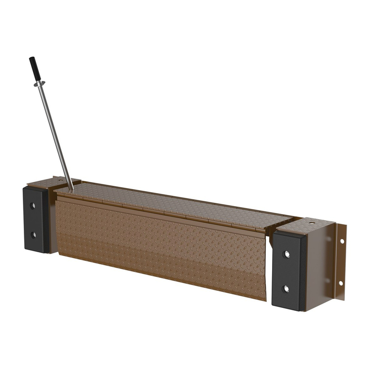
When the unit is first installed, make a detailed record of its condition. Include observations about all features:
hinges, the power unit (cylinder, pump, hoses, etc.), welds, the frame (particularly the mounting plate and cylinder
mounting brackets), dock plate, bridge plate, control box, and bumper assemblies. Thoroughly photograph the unit in
both the raised and home positions. Photograph all labels applied to the leveler and control box. Add the
photographs to the record. Describe where each label is located. Press the control button until the leveler is fully
extended/raised; then release the button and watch the leveler return to the home position. Write a detailed
description of the cycle and/or make a video recording of the leveler in operation. This record establishes “normal
condition”. During future inspections, compare your observations to the record to determine if the unit is in normal
condition. See Inspections & Maintenance.
INSPECTIONS AND MAINTENANCE
Before beginning maintenance, secure the leveler in the extended position. For example, use at least 2 props or
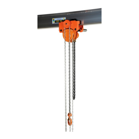
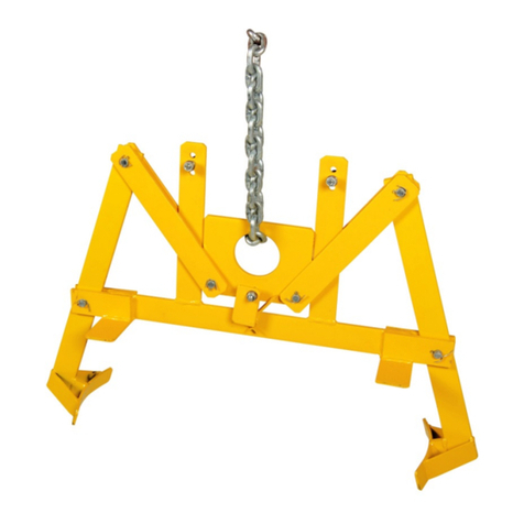
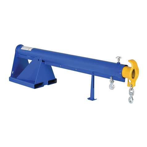
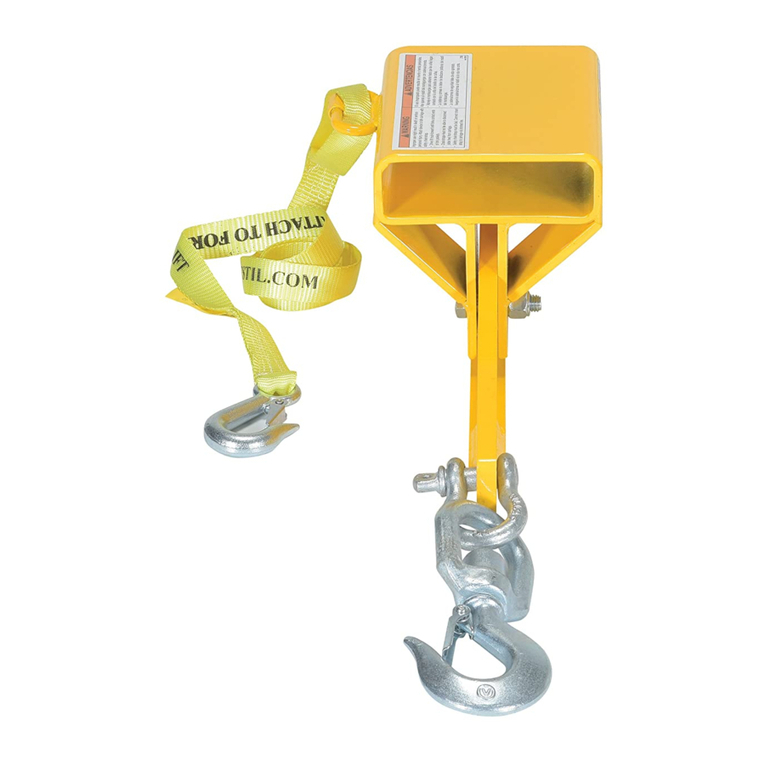
attach a locking plate clamp to the bridge plate and lift it with an overhead lifting device like a hoist or forklift boom. It
is strongly recommended that more than one method of securing the leveler be applied each time it is serviced to
provide redundancy if one method fails.
(A) Inspect the unit at least once per week for the following:
1.) Frayed wires and loose conduit fittings. Repair or replace wiring/conduit as necessary.
2.) Damage and deformation of the structural members, cylinder brackets, etc.
3.) Run the leveler through a complete cycle. Listen for unusual noises. Watch the dock plate and bridge plate
for binding or unusual movement. Grease the hinges if the plates are noisy as they move but are otherwise
in normal condition.
(B) Inspect the following at least once per month:
1.) Oil leaks – check the hose, cylinder, fittings, etc. for oil leaks. Also check the oil level in the reservoir. Oil should
be 1” to 1½” below the fill hole in the reservoir. If you need to add oil, or if the oil needs to be replaced, only use
anti-wear hydraulic oil with a viscosity grade of 150 SUS at 100°F, (ISO 32 at 40°C), for example AW 32 or HO
150 hydraulic oil or a non-synthetic transmission fluid. Synthetic transmission fluid can be used, but the system
must first be flushed with the synthetic fluid before the reservoir is filled.
2.) Hydraulic hose and electrical wiring – check the hose and electrical wires for damage. Replace the hose if it is
leaking, bulging, or cracking.
3.) Hinge and cylinder pivot points – check for excessive wear at all pivot points. Apply grease to all hinges
through the grease zerks. Examine both cylinder mounting brackets for damage.
4.) Welds – check all welds for cracks and signs of metal fatigue, especially around hinges and cylinder mounting
brackets.
5.) Hardware – examine each anchor bolt and the concrete around it. Tighten any bolt that is loose. The leveler
must be rigidly anchored to the dock at all times. The frame should not move (e.g. rock or wobble) while the
leveler operates. Make sure that the bolt holes in the mounting plate are not elongating, cracking, etc. Also
inspect the cylinder mounting bolts (part no. 17165 in Exploded View on p. 3).
6.) Labels – confirm that each label is in place and in good condition. Refer to the Labeling Diagram on p. 16.
7.) Leveler surfaces - clean the surfaces of the leveler, underneath and around the power unit. Remove
corrosion/rust and apply touchup paint to all areas where the finish is damaged.
(C) Yearly Maintenance
1.) Thoroughly grease the hinges and both cylinder pivot points. See Exploded View on p. 3.
2.) The oil should be changed if it darkens, becomes gritty, or has a milky appearance (indicating the presence
of water). Replace the original oil with anti-wear hydraulic oil, viscosity grade 150 SUS at 100°F, (ISO 32
at 40°C). Examples of replacement oils include AW 32 or HO 150 hydraulic oil or a non-synthetic
transmission fluid. Synthetic transmission fluid can be used only if the system is flushed with the synthetic
fluid before the reservoir is filled.