Zepro ZDK 250 135 User manual

ZEPRO
Tel.: +46 (0)10-459 05 00
78353TL
2022-06-03
Installation Instructions
Tail Lift
ZDK 250 135/155


ZDK 250 135/155Contents
3www.zepro.com
Contents
1 Important information ..................................................................................... 5
1.1 Attention! ................................................................................................ 5
1.2 Technical support.................................................................................... 5
1.3 Identication ........................................................................................... 6
1.4 CE marking............................................................................................. 6
1.5 Product approval ................................................................................... 6
1.6 Hydraulic oil ............................................................................................ 6
1.7 Guarantee............................................................................................... 6
1.8 Repainting .............................................................................................. 7
1.9 Battery maintenance............................................................................... 7
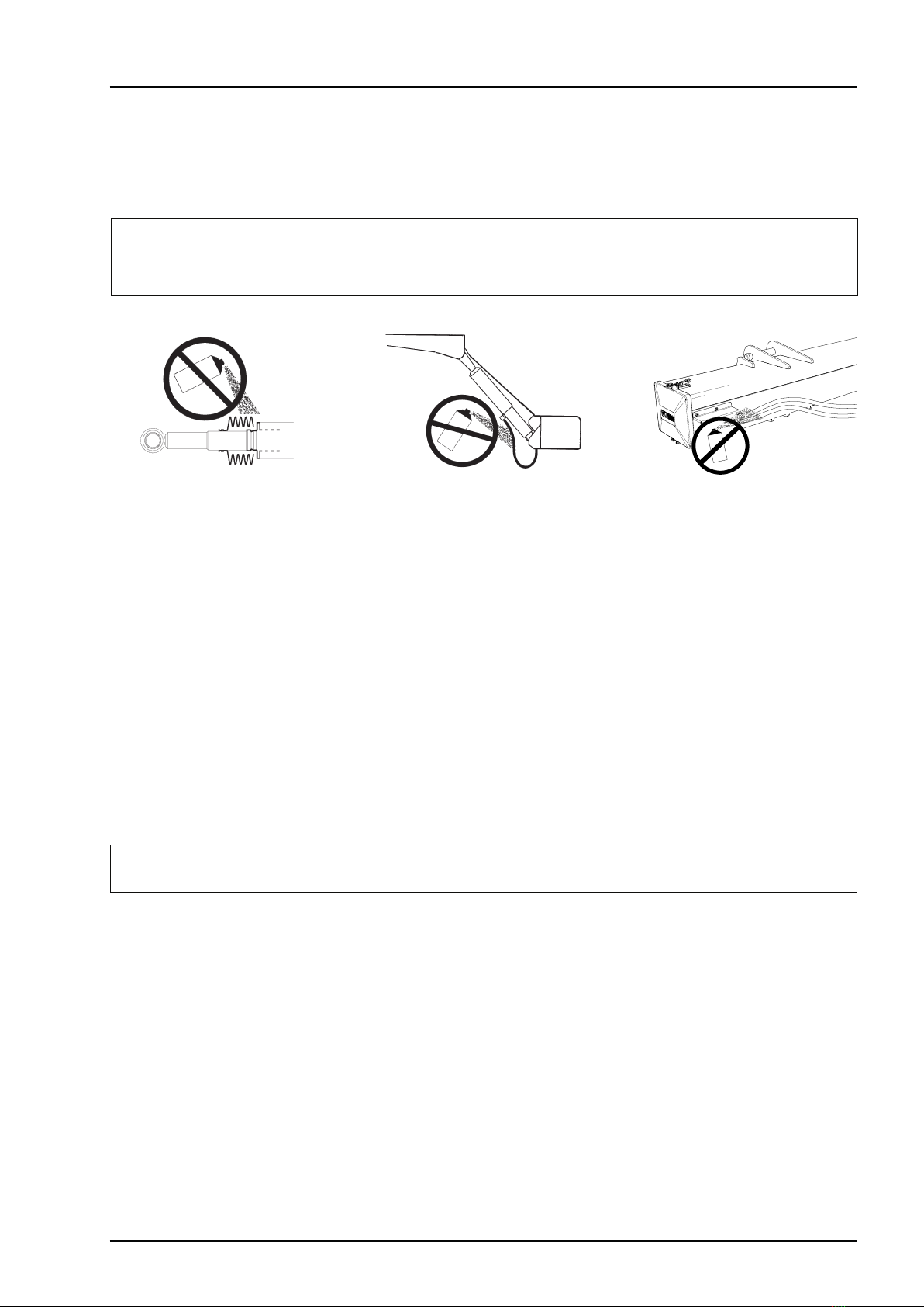
2 Safety rules ....................................................................................................... 8
2.1 Moving parts - free movement................................................................ 8
2.2 Connection of third-party equipment is forbidden................................... 8
2.3 Installation .............................................................................................. 8
3 Before installation ............................................................................................ 9
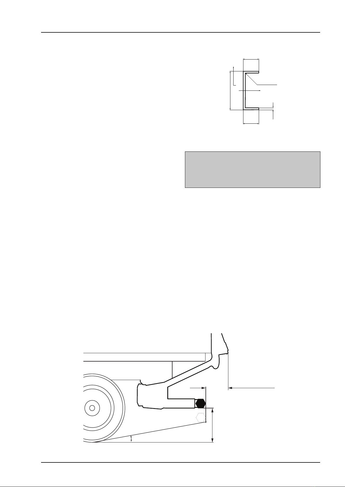
3.1 Vehicle chassis requirements................................................................. 9
3.2 Statutory dimensions .............................................................................. 9
3.3 Calculating the installed dimensions .................................................... 11
3.4 Rear member cut-outs.......................................................................... 14
3.5 Prepare the tail lift................................................................................. 15
3.6 Temporary connection .......................................................................... 17
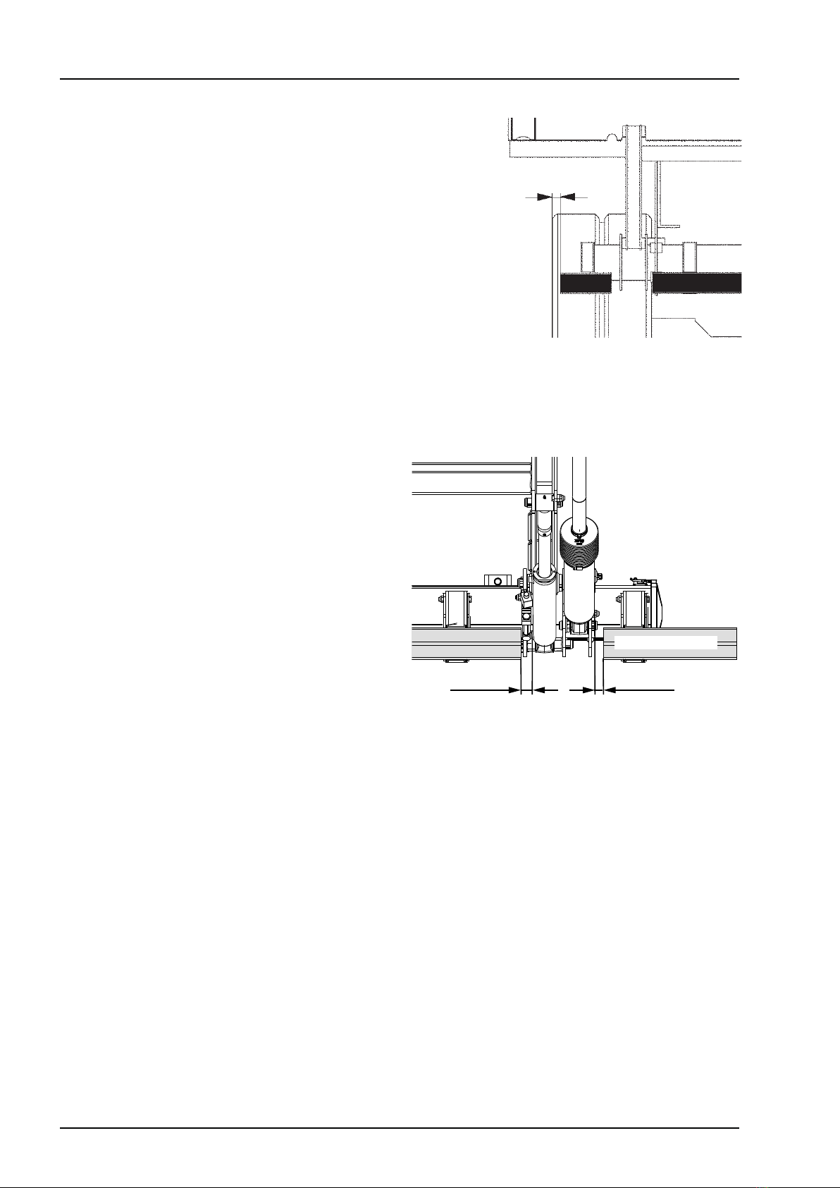
4 Installation ..................................................................................................... 20
4.1 Platform ................................................................................................ 23
4.2 Armstops .............................................................................................. 28
4.3 Sealing strip (horizontal)....................................................................... 29
4.4 Sealing strip (vertical) ........................................................................... 29
4.5 Purging the cylinders ............................................................................ 31
4.6 Angle sensor / Inclinometer.................................................................. 32
4.7 Controllers ............................................................................................ 34
5 Cable routing ................................................................................................. 36
5.1 General................................................................................................. 36
5.2 Sizing electrical systems ...................................................................... 37
5.3 Main power cable, earth cable, main fuse and main switch ................. 38
5.4 Control power cable.............................................................................. 40
5.5 Open platform alarm............................................................................. 40
5.6 Foot controller / Warning lights............................................................. 40
6 Connection...................................................................................................... 41
6.1 Cable grommet ..................................................................................... 41
6.2 Connection ........................................................................................... 42
7 Powering up the tail lift.................................................................................. 50

ZDK 250 135/155
4
Contents
www.zepro.com
8 Electrical and hydraulic diagrams ................................................................ 51
8.1 ZDK 250 MA (TLC-B1) ......................................................................... 51
8.2 ZDK 250 MA (ZePRO1)........................................................................ 52
8.3 ZDK 250 MA with electric autotilt, Angle sensor IFM (TLC-B1)............ 53
8.4 ZDK 250 MA with electric autotilt, Inclinometer (ZePRO1)................... 54
8.5 ZDK 250 MA with electric autotilt, Angle sensor IFM (ZePRO1) .......... 55
8.6 ZDK 250 DA (ZePRO1) ........................................................................ 56
9 Lubrication and oil level check ..................................................................... 57
9.1 Lubrication ............................................................................................ 57
9.2 Oil level check ...................................................................................... 57
10 Marking............................................................................................................ 58
10.1 Loading diagram................................................................................... 59
10.2 Identicationplate................................................................................ 60
10.3 Work area ............................................................................................ 60
10.4 Warning tape ....................................................................................... 60
10.5 Controller sticker................................................................................... 61
10.6 Danger area ......................................................................................... 62
10.7 Warningags....................................................................................... 62
11 Testing and verification ................................................................................. 63
11.1 Static load test ...................................................................................... 63
11.2 Dynamic load test. ................................................................................ 64
11.3 Test of safety functions......................................................................... 64
12 Registration .................................................................................................... 65
13 Specifications ................................................................................................ 65
13.1 Weights ................................................................................................ 65

ZDK 250 135/155Important information
5www.zepro.com
1 Important information
1.1 Attention!
The following warning signs appear in the installation instructions and are intended to draw your attention to cir-
cumstances that can potentially cause problems, near misses, personal injury and/or damage to the product, etc.
mWARNING!
WARNING
indicates a potential hazard, which if ignored may lead to serious, life-threatening injury.
mCAUTION!
CAUTION
indicates a potential hazard, which if ignored, may lead to minor injuries.
IMPORTANT!
IMPORTANT indicates a risk of equipment damage.
NOTE!
NOTE refers to additional information that may help the reader understand, or perform, a given operation.
1.2 Technical support
If technical support is needed, please contact ZEPRO. Tel: +46 (0)10-459 05 04, E-mail: [email protected].
Always be ready to state the tail lift’s production number to guarantee you receive the correct information. The
productionnumberisgivenontheidenticationplatelocatedonthetailliftframe.
Image 1. Identification plate

ZDK 250 135/155
6
Important information
www.zepro.com
1.3 Identication
E.g. ZDK 250 - 135 MA
_ _ _ _ _ _ - _ _ _ _ _
ZDK = Standard model
Max. lifting capacity x 10 (kg)
Max. lifting height - 135 = 1340 mm
- 155 = 1530 mm
Cylinder model, MA = Double acting Adjustable Tilt
Single acting Single speed Lift
DA = Double acting Adjustable Tilt
Double acting Single speed Lift
1.4 CE marking
ZEPRO tail lifts for sale on the European market are CE marked (Conformité Européenne). The manufacturer
guarantees that the product complies with the EU Machinery Directive.
Followtheinstallationinstructionscarefully.Modicationsnotapprovedinwritingbythemanufacturerarenot
permitted. Welding is not permitted.
1.5 Product approval
Properly assembled, this product meets relevant requirements according to EN 1756-1:2001 + A1:2008.
1.6 Hydraulic oil
If the hydraulic oil needs to be replenished, only the oil recommended by ZEPRO is permitted to be used.
Hydraulicsystemswithhydraulicoiltankswithoutlabellingareonlypermittedtobelledwithhighlyrened
mineral oil (art. no. 21963, 1 litre).
Hydraulicsystemswithhydraulicoiltanksmarkedwithaspecicationforthehydraulicoilareonlypermitted
tobelledwiththeoilspeciedonthelabel.
1.7 Guarantee
The ZEPRO warranty applies only if assembly has been carried out according to ZEPRO's assembly instruc-
tions by a ZEPRO approved bodybuilder.
Afterinstallation,testingandverication,registerthetaillift’sdeliverycardtovalidatethewarranty.

ZDK 250 135/155Important information
7www.zepro.com
1.8 Repainting
Image 2. Piston rods, cyl-
inder covers and boots
Image 3. Hydraulic hoses Image 4. Cables
1.9 Battery maintenance
When storing for longer than 1 week, it is recommended to disconnect the lift from the battery via the main
switch or by releasing the lift’s main fuse, in order to reduce the risk of the battery discharging. The length of
time the vehicle can be stored without the battery charge level becoming too low depends on the condition of
the battery, the charge level prior to storage and how much power other components in the vehicle take from
the battery. After a period of storage, the battery must always be charged fully before operating the lift.
When the lift is operated repeatedly without
starting or using the vehicle during lift installation or carrying out
service and repairs, use the battery charger between operations to maintain battery charge
.
IMPORTANT!
The battery charger must be disconnected when operating the lift. Risk of material damage.
IMPORTANT!
Piston rods and cylinder covers must not be painted. Among other things, this can damage the cylinder gaskets.
Boots, hydraulic hoses and cables may not be coated/painted as the solvent in the paint can damage the hoses and cables and
impair durability.

ZDK 250 135/155
8
Safety rules
www.zepro.com
2 Safety rules
2.1 Moving parts - free movement
min. 40 mm
10º
10º
Image 5. Clearance to the closest part of
the cylinder must be at least 40 mm
Image 6. The platform may not be tilted
down more than 10º from the horizontal
2.2 Connection of third-party equipment is forbidden
mWARNING!
Connecting third-party equipment (electric or hydraulic) to Zepro tail lifts is forbidden. Connecting third-party equipment could
interfere with the lift’s system and its safety functions. Risk of injury and damage. If it is necessary to install other equipment,
check the vehicle manufacturer’s body instructions and use the attachment features on the vehicle.
2.3 Installation
mWARNING!
Installation where the platform cannot reach ground level is prohibited.
mWARNING!
ZEPRO tail lifts are only approved for installation using ZEPRO assembly kits.
IMPORTANT!
All specied tightening torques apply when using torque wrench or screw/nut runner with torque control. Torque spread max ±5%.
mWARNING!
During nal inspection*, the space occupied by the moving
cylinders must be cleared and made safe. There is a risk
of collision between the cylinder and the following items:
subframe, truck chassis, beam for rear light (number
plate) and the chassis bracket of the lift (with a short
overhang).
**Final inspection to be carried out with the platform at
the vehicle oor and tilted down 10°. The clearance from
the closest part of the cylinder must be at least 40 mm.
mWARNING!
The platform may not be tilted down more than 10º from
the horizontal.

ZDK 250 135/155Before installation
9www.zepro.com
Max. 450 mm.
(Air suspension)
Max. 500 mm.
(Conventional suspension)
Max 300 mm.
8º
Image 7. Cross section of vehi-
cle chassis frame beam
70
70
220
4
R6(x2)
X
Y
3 Before installation
3.1 Vehicle chassis requirements
In order to comply with the applicable underrun
protection standards,
there are requirements for the
vehicle chassis on which the rear tail lift is mounted.
The moment of inertia in a cross-section on the current
frame beam (excluding any support frame) shall not be
less than 937 cm4. Thus the frame beam cross-section
must measure at least 220x70x4 mm, which cor-
responds to a minimum moment of inertia of 937cm4
around the x-axis. See Image 7. If in doubt, contact
ZEPRO for support.
3.2 Statutory dimensions
Distance between the beam and the ground when the vehicle is unloaded:
• Max. 450 mm for vehicles with air suspension.
• Max. 500 mm for vehicles with conventional suspension.
If the exit angle with the above setting is less than 8º, the distance between beam and ground in an unladen
vehicle may be increased until the angle is 8º, but to max 550 mm.
Horizontal distance from the outermost part of the platform to the underrun protection: Max 300 mm.
See Image 8.
NOTE!
The underrun protection must be located further back and lower.
Image 8. Statutory dimensions
mWARNING!
The above dimensions are the minimum permitted for
the installation of underrun protection. The strength
requirements for mounting the tail lift usually require
larger dimensions.

ZDK 250 135/155
10
Before installation
www.zepro.com
0-100 mm.
Horizontal distance from the outer edge of the member
to the outside of the wheel: Max. 100 mm.
See Image 9.
The lateral distance between the underrun protection
and the moving parts of the tail lift must not exceed
25 mm. See Image 10.
Each of the individual parts of the underrun protec-
tion must have a surface area of at least 350 cm2.
See Image 10.
Image 9. Statutory dimensions
Image 10. Statutory dimensions
Max 25 mmMax 25 mm
Min. Area: 350 cm2

ZDK 250 135/155Before installation
11www.zepro.com
3.3 Calculating the installed dimensions
For ease of installation it is best to calculate and specify the necessary dimensions in advance. Determine
theCdimensionrst,thenobtaintheotherdimensionsfromtherelevanttable.Trytoplacetheliftashighas
possiblewithintheCdimensionspeciedinthetable.
3.3.1 C dimension
TheCdimensionisthedistancebetweenthetopofthesupportframeandthevehicleoorlevel.Thisdimen-
sion determines the space the lift
needs beneath the body (dimension D) and the distance from the lift arms in
theirupperpositiontovehicleoorlevel(dimensionA).
3.3.2 D dimension
The D dimension is the space the lift needs, measured from the rear edge of the body to the front edge of the
support frame (in the direction of the vehicle). Once the C dimension is determined, the D dimension can be
obtained from the table.
3.3.3 A dimension
The A dimension is the space provided for the rear member, i.e. the space there will be between the 1st
boomandthevehicleoorwiththeliftintheraisedposition.TheAdimensiondependsontheCdimension
3.3.4 H dimension
TheHdimensionistheheightfromtheground(unloaded)tothevehicleoorlevel.TheHdimensionmust
not be greater than the maximum lifting height of the lift. The lift platform must always be able to reach
ground level.

ZDK 250 135/155
12
Before installation
www.zepro.com
Image 11. ZDK 250-135
Image 12. ZDK 250-155
C D A
610 620 197
570 669 182
520 721 163
470 764 144
420 800 126
360 835 104
815
max. 1530
220
C
A
40 D
C D A
715 680 229
680 725 212
630 781 194
580 828 179
530 869 164
480 904 145
430 934 129
210
180
730
max. 1340
220
C
A
40 D
210
180

ZDK 250 135/155Before installation
13www.zepro.com
Image 13. ZDK 250
1014
min. 750 - max. 930
1435
2424
1515
1870
D28
336
35
62
305
133-301
617-817
Image 14. ZDK 250

ZDK 250 135/155
14
Before installation
www.zepro.com
3.4 Rear member cut-outs
It is often necessary to create cut outs in the rear beam to provide space for the platform arms when the
platform is in the upper position. The size of the cut outs depends on the calculated installed dimension “A”,
see illustration below.
1. Measure and mark the location and depth of the cut outs on the rear beam. The
two cut outs must be
centred on the rear beam, i.e. both cut outs must be an equal distance from the mid-point of the beam
.
2. Cut along the markings.
3. Grind away any burrs or sharp edges.
Image 15. ZDK 250
994
245 245
Amax

ZDK 250 135/155Before installation
15www.zepro.com
3.5 Prepare the tail lift
1. Position the support frame under the vehicle’s chassis.
2. Remove the protective cover mounted using to quick release locks; see Image 16.
3. Fold out the control card / relay card (B) and loosen the cabling at the connector on the hydraulic unit; see
Image 17 and Image 18.
4. Release the hydraulic unit by unscrewing the wing nut and corresponding screw (C); see Image 19 and
pull out the hydraulic unit until the tank cap
is accessible; see Image 21.
mCAUTION!
Make sure no cables are pinched or in any other way damaged when the control card / relay card is folded out or removed.
Do not pull out the hydraulic unit more than necessary; make sure it is not pulled completely out of the frame, as this can
entail a risk of injury and damage to the equipment.
Image 16. Remove the protective cap
C
AB
Image 17. Release mechanism
Image 18. Connection socket Image 19. Releasing the hydraulic unit

ZDK 250 135/155
16
Before installation
www.zepro.com
54
8
5
3
Image 20. Where necessary, replace the
transport plug with a regular tank cap
Image 21. Hydraulic unit and relay card
RELAY CARD
TANK CAP
MOTOR
OIL TANK
SOLENOID
VALVE HOUSING
5. Checkwhetherthehydraulictankisttedwitha
transport plug seal. If so, replace it with the regu-
lar tank cap supplied.

ZDK 250 135/155Before installation
17www.zepro.com
3.6 Temporary connection
When the tail lift is installed, it is sometimes necessary to operate its functions in order to change the position
of the cylinders and the lift arms. Temporarily connect the lift to enable the lift functions.
1. Connect a suitable control device to Ctrl 1/C1, see section 3.6.2/3.6.3.
2. Connect the tail lift’s main power cable to battery +12/24V.
3. Connect the negative battery terminal to the tail lift’s earth cable (GND).
4. Relay card TLC-B1: When operating,
connect
a cable (jumper) between an available power supply con-
nection (+) and CS on the relay card to simulate switch CS being on. Remove the cable immediately
after completed operation.
Control card ZePRO1: When operating,
connect
the cable (jumper) between the CSPWR and CS on the
control card to simulate that the CS switch is turned on. Remove the jumper immediately after completed
operation.
mWARNING!
Take great care while running the lift functions and make sure nothing gets pinched: risk of personal injury and material damage.
Image 22. Temporary connection
3.6.1 Battery maintenance
When installing the lift, when the lift is operated repeatedly,
the battery charger must be used between opera-
tions to maintain the battery charge level
.
The battery charger must not be connected when operating the lift. Risk of
material damage
.
IMPORTANT!
Ctrl 4
Spiral
Ctrl 3
Radio
Ctrl 2
Ctrl 1
Contrl Power
Sensor Power
Ground
IN OUT
Ai 1
Ai 2
Di 1
Di 2
Di 3
Di 4
Di 5
Di 6
PA-
PA+
CSPWR
CS
+
B
E
C
2H1
B
E
C
2H2
B
E
C
Lock
B
E
C
Lock
U7
U6
U5
U4
U3
U5
U4
U2
U1
U0
Ctrl 6
Out
In
GND
LLED
Ctrl 5
Outputs
Sensors
ZePRO1
Jumper
Ctrl 1
TLC-B1
WL1 U7 U6 U5 U5 U4 U4 U3 U2 U1 U0
++
WL2
PA+
S5
S1+
S4
S3
S2
S1
S5+
S4+
S3+
S2+
PA-
CS+
Down
2H
Out
Down
Down
C1+
C1+
Up
Tilt
In
C2+
Up
Tilt
C3+
Up
CS
+
U1
U2
U3
U0 +
Jumper
C1

ZDK 250 135/155
18
Before installation
www.zepro.com
3.6.2 Connecting the control device to the TLC-B1 relay card
The connection of warning lights and the most commonly occurring controller (CD (Control Device)) models
isshownbelow.Possiblecontrollermodelsvarydependingonliftmodel,congurationandrelevantmarket.
mWARNING!
Make sure the control relay is disconnected from power before connecting. Connecting more than one controller to each
connection is not permitted. Risk of material damage.
WL1 U7 U6 U5 U5 U4 U4 U3 U2 U1 U0
++
U0 +
+
U1
U2
U3
WL2
PA+
S5
S1+
S4
S3
S2
S1
S5+
S4+
S3+
S2+
PA-
CS
CS+
Down
2H
Out
Down
Down
C1+
C1+
Up
Tilt
In
C2+
Up
Tilt
C3+
Up
Ctrl 1
CD4
Up
Tilt
2H
Down
Up
Tilt
Down
2H
CD1
CD19
Up
Down
Tilt up
Tilt down
2H
2H
Tilt down
Up
Down
Tilt up
Black C1+
White ( )*
Brown Up
Yellow Down
Blue Tilt
Black C1+
White ( )
Brown Up
Yellow Down
Blue Tilt
Black C1+
White ( )
Brown Up
Yellow Down
Blue Tilt
Pink 2H
* applies to controllers with heating only
Black C1+
Blue 2H
When connecting Warning Lights:
Loop between S3 - S3+

ZDK 250 135/155Before installation
19www.zepro.com
3.6.3 Connecting the control device to the ZePRO1 control card
The most commonly occurring controller (CD Control Device) models are shown below.
Possible controller
modelsvarydependingonliftmodel,congurationandrelevantmarket.
mWARNING!
Make sure that the control card is disconnected from the power before connecting. Connecting more than one controller to each
connection is not permitted. Risk of material damage.
Ctrl 4
Spiral
Ctrl 3
Radio
Ctrl 2
Ctrl 1
Contrl Power
Sensor Power
Ground
IN OUT
Ai 2
Ai 1
Di 1
Di 2
Di 3
Di 4
Di 5
Di 6
PA-
PA+
CSPWR
CS
+
B
E
C
2H1
B
E
C
2H2
B
E
C
Lock
B
E
C
Lock
U7
U6
U5
U4
U3
U5
U4
U2
U1
U0
Ctrl 6
Out
In
GND
LLED
Ctrl 5
Outputs
Sensors
o
Brun B
Gul E
Blå C
* Blå 2H
CD1, CD2
B
C
2H1
E
CD15
B
C
2H
E
Black (+)
Black (+)
2H Black (+)
Black (+)
White (-)*
White (-)*
Ctrl 4
Spiral
Ctrl 3
Radio
Ctrl 2
Ctrl 1
Contrl Power
Sensor Power
Ground
IN OUT
Ai 2
Ai 1
Di 1
Di 2
Di 3
Di 4
Di 5
Di 6
PA-
PA+
CSPWR
CS
+
B
E
C
2H1
B
E
C
2H2
B
E
C
Lock
B
E
C
Lock
U7
U6
U5
U4
U3
U5
U4
U2
U1
U0
Ctrl 6
Out
In
GND
LLED
Ctrl 5
Outputs
Sensors
o
White (-) must be con-
nected to the connec-
tions marked “Ground”.
Brown B
Yellow E
Blue C
Green 2H
Brown B
Yellow E
Blue C
Blue 2H
Brown B
Yellow E
Blue C
Pink 2H
White (-)
Black (+)
* applies to controllers with heating only
Up
Down
Tilt up
Tilt down
2H
2H
Tilt down
Up
Down
Tilt up

ZDK 250 135/155
20
Installation
www.zepro.com
4 Installation
NOTE!
Also consult the vehicle manufacturer’s body instruc-
tions and Zepro’s instruction booklet before installation.
Zepro tail lifts are only approved for installation with Zepro
assembly kits.
mWARNING!
4.1 Support frame
1. Measure and mark the midpoint of the rear
member of the vehicle. See Image 23.
2. Bolt or spot-weld the mounting jig
to the rear
member, so that both
mid-points are aligned. See
Image 24. Art.no 51274
.
3. Position the support frame under the vehicle
chassis.
4. Raise the lift arms to their highest position.
5. Attach the lift arms to the eye of the jig. Use the
steel platform’s normal bolts.
6. The support frame should be positioned as high
aspossiblewithinthespeciedCdimension.
Adjust the frame to the ideal height under the
chassis. A workshop jack is useful. The frame
mustbepositionedparallelwiththeoorofthe
vehicle body and must not be in contact with the
vehicle chassis; there must be a few millimetres
of play. If necessary, adjust the angle of the
arms by carefully operating the lift.
7. Install the brackets on the support frame so that
its opening is facing towards the front of the
vehicle, and adjust the position of the frame so
they are in contact with the vehicle chassis.
8. InstalltheU-prolewithassociatedwashersand
nuts, but do not tighten these. Screw the bolts
alternatelyuntiltheU-proleisalignedincontact
Image 23. Measure and mark the midpoint of
the rear member of the vehicle.
Image 24. Bolt or spot-weld the
mounting jig to the rear member
Art. no. 51724
Image 25. Mounting jig,
Image 26. Install the U-profile with as-
sociated was hers and nuts
This manual suits for next models
1
Table of contents
Other Zepro Lifting System manuals

Zepro
Zepro Z 45-90 User manual

Zepro
Zepro ZHZ 500-850 User manual

Zepro
Zepro Z 10 User manual

Zepro
Zepro ZT MK2 User manual

Zepro
Zepro ZHZ 500 User manual

Zepro
Zepro ZHD-1500-MA-DA User manual

Zepro
Zepro Z 2500-130 Series User manual

Zepro
Zepro ZAHD 150/200 User manual

Zepro
Zepro Z 150-135 User manual

Zepro
Zepro Z 2500-130 User manual

Zepro
Zepro ZHD 2500-130 User manual

Zepro
Zepro ZS MK2 User manual

Zepro
Zepro Z 1500 User manual

Zepro
Zepro ZN 2500-130 User manual

Zepro
Zepro ZHD 1500 Original operating manual

Zepro
Zepro Z 1500-135 User manual

Zepro
Zepro 78826TL User manual

Zepro
Zepro Z3N 75-100 User manual

Zepro
Zepro Tail lift User manual