Hycontrol VF04 Owner's manual

Issue 5 June 2019
VF04
VF04 2-WIRE GUIDED (TDR)
LEVEL TRANSMITTERS
USER AND PROGRAMMING MANUAL
Hycontrol Ltd, Larchwood House, Orchard Street,
Redditch, Worcestershire, UK. B98 7DP
Tel: +44 (0)1527 406800 Fax: +44 (0) 1527 406810
Company registered in England No: 1755684

2 / 51
GUIDED MICROWAVE LEVEL MEASUREMENT

3 / 51
C O N T E N T S
1. INTRODUCTION 4
2. ORDER CODE 5
3. TECHNICAL DATA 5
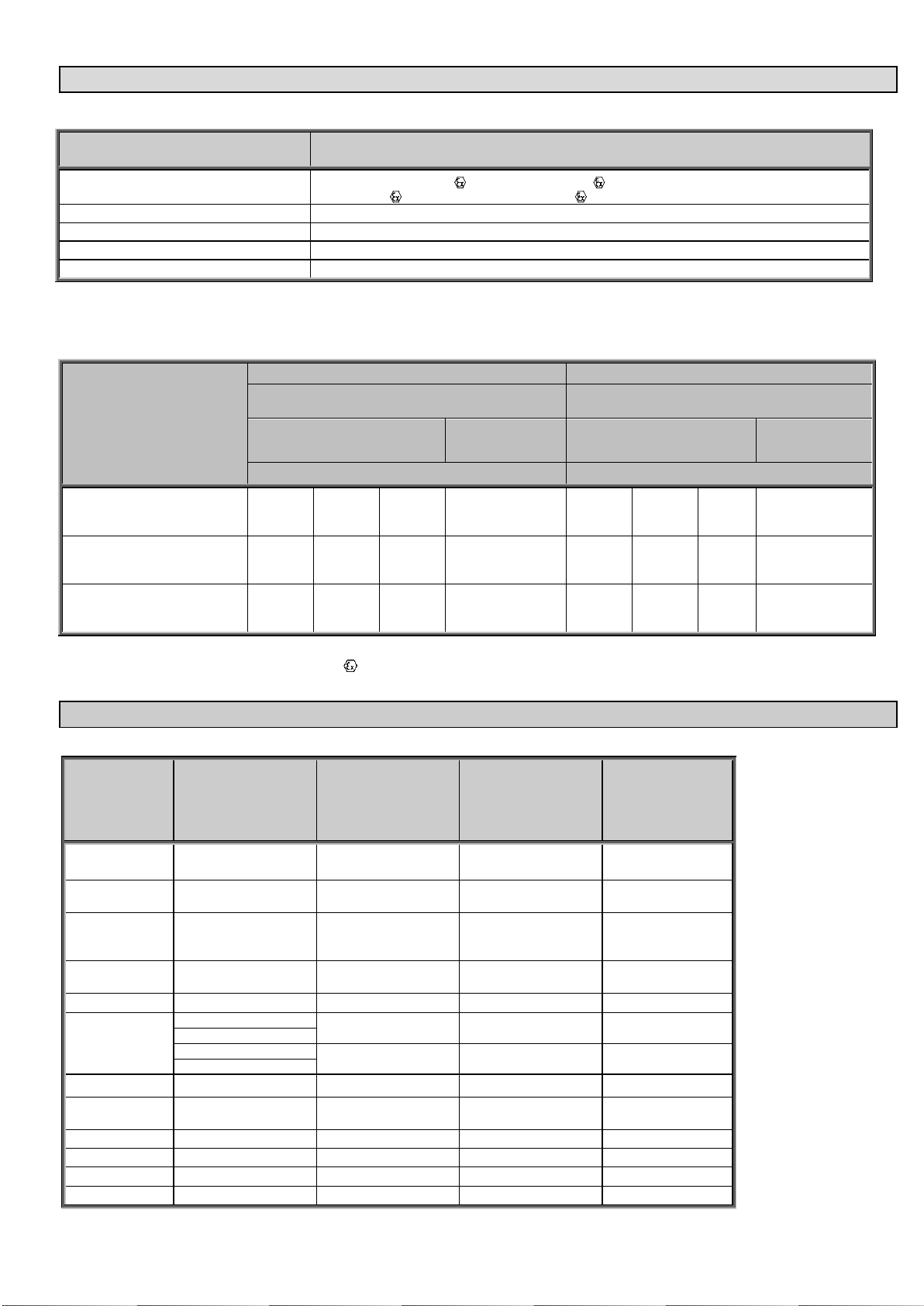
3.1 ATEX, Explosion protection, Ex markings, Ex limit data 6
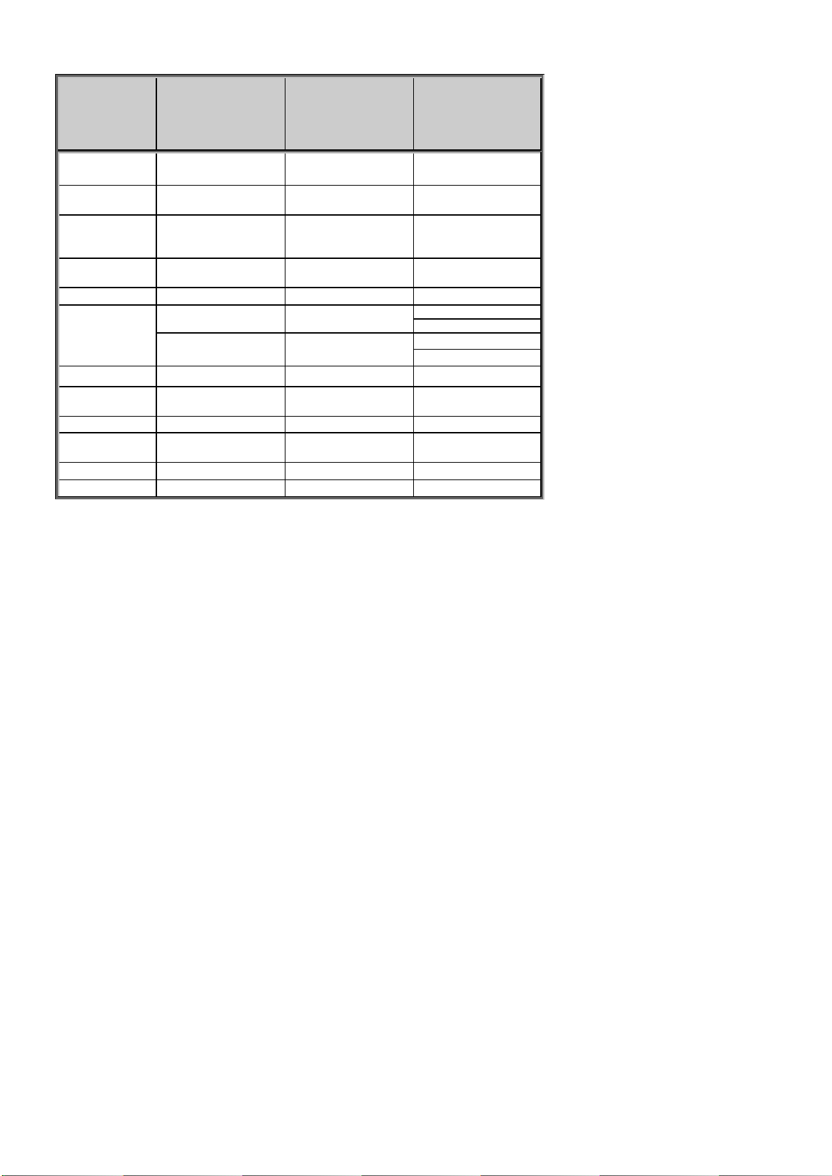
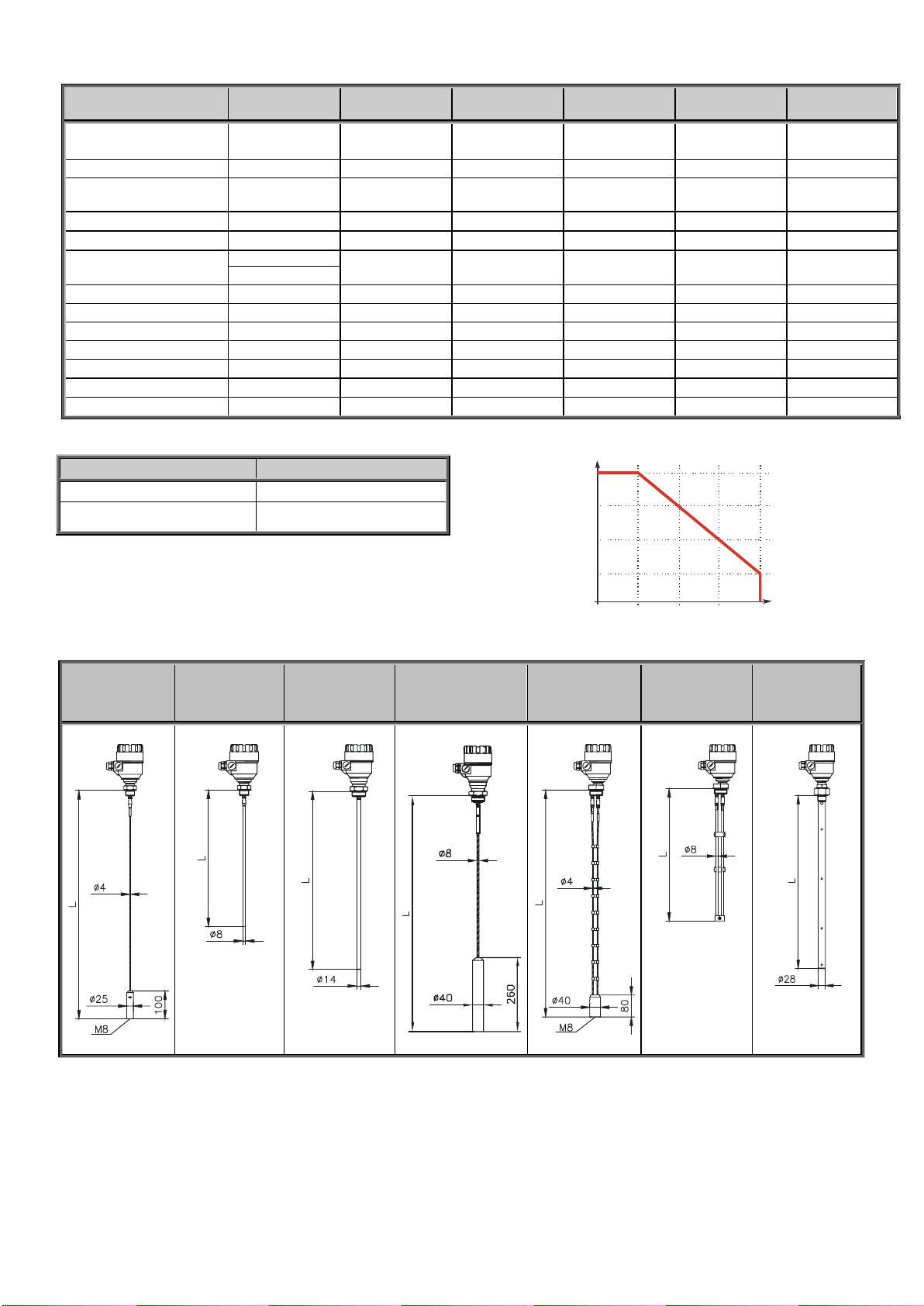
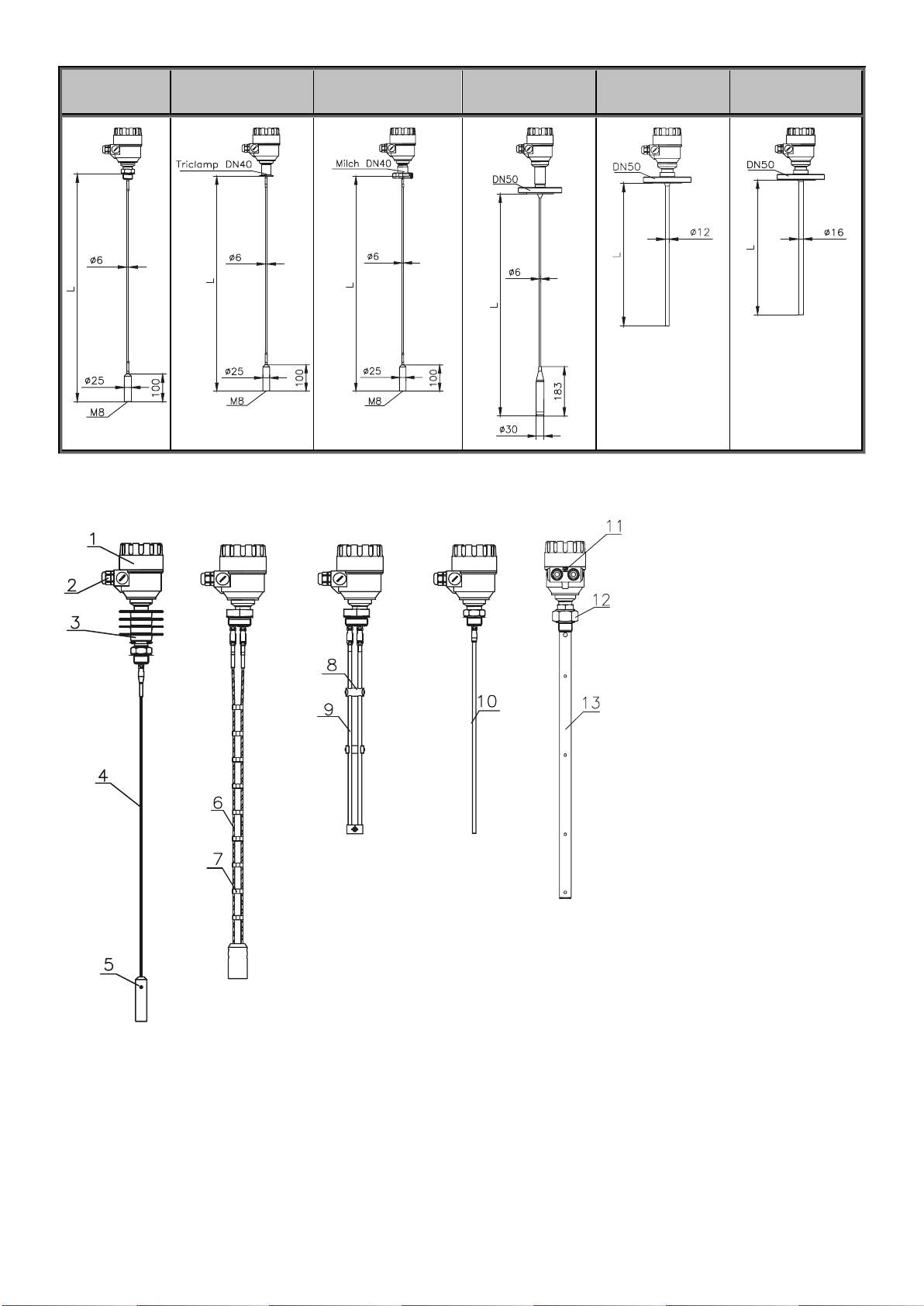
3.2 Technical data of the probes 6
3.3 Accessories 10
3.4 Safety regulations for the Ex approved units 10
3.5 Maintenance and repair 10
4. MECHANICAL INSTALLATION 11
4.1 Handling and storage 11
4.2 Mounting on the tank 12
4.2.1 Installation instructions: general notes 12
4.2.2 Specific installation instructions: instrument - solid applications 15
4.3 Wiring 16
4.3.1 BUS ( HART®) communication 19
4.4 Power-on and start-up 19
4.5 Available user interfaces 19
5. PROGRAMMING 20
5.1 Programming with HyView software 20
5.1.1 HyView: installation and operation. 20
5.1.2 Summary of Parameter functions In HyView 24
5.1.3 Configuration: configuration examples 29
5.2 Programming with VGF-DISPLAY display unit 35
5.2.1 VGF-DISPLAY display unit 35
5.2.2 VF04’s behaviour in manual programming mode 36
5.2.3 Manual programming requires a VGF-DISPLAY module 36
5.3 Programming with HART® handheld (HHC) Communicator 37
5.3.1 Characters available for alpha-numerical data functions in HyView and on the HART®console 41
5.4 VF04 2-wire T.D.R. meter characteristics 41
5.4.1 Instrument operating logic when the reflection is lost 42
5.4.2 Gain and voltage amplitude 43
5.4.3 Typical signal trends 45
5.4.4 Automatic adjustment 46
5.4.5 Level measurement when more than one phase or layer in the tank 47
5.5 Troubleshooting 48
APPENDIX 1. ATEX SAFETY GUIDELINES 50

4 / 51
Thank you for choosing a HYCONTROL instrument.
We are sure that you will be satisfied throughout its use!
1. INTRODUCTION
Application
The VF04 2-wire level instrument uses the Time Domain Reflectometry (TDR) measuring principle and two-wire technology for level measurement.
It is designed for measuring the distance, level and volume of liquids, pastes, slurries and powder products.
The device operates in a tank, silo, rigid pipe, process vessel and side chamber.
The device is HART capable, it can be programmed using a HART® Handheld Communicator (HHC) and HyView software supplied as standard with the instrument.
Operating principle
The VF04 2-wire guided microwave level transmitter uses the TDR (Time Domain Reflectometry) principle. The instrument sends low power nanosecond wide pulses
along an electrically conductive rod, cable or coaxial probe with a known propagation speed (the speed of light). As the pulse reaches the surface of the medium or
interface of two liquids (altered dielectric constant r), a part of it is reflected back to the electronic module. The size of the reflected signal depends on the dielectric
constant rdifference of the mediums or layers. (When measuring to the surface of still water through air the reflected signal's strength will be approx. 80% of the
emitted signal). The reflected pulse is detected as an electrical voltage signal and processed by the electronics. Distance is directly proportional to the flight time of the
pulse. The measured distance data is converted to a level then to a 4-20 mA current and HART signals and is displayed on the LCD display. From the level data further
derived measuring values can be calculated such as volume and mass. The TDR technology is unaffected by the other properties of the medium as well as that of the
space above it.

5 / 51
2. ORDER CODE
VF04
-
-
*
2-wire guided microwave level transmitter
TYPE
CODE
PROBE /PROC.CONN.
CODE
HOUSING
CODE
INSERTION
LENGTH
CODE
INSERTION
LENGTH
CODE
OUTPUT /EX
CODE
Transmitter
T
Coaxial / 1” BSP
A
Aluminium
4
Coaxial, Rod,
Twin rod
Coaxial, Rod,
Twin rod
4 –20 mA + HART / Normal
4
High temp.
transmitter
H
Coaxial / 1” NPT
B
Stainless
steel
6
4 –20 mA + HART / Ex tD**
5
Coaxial / 11/2” BSP
C
0m
0
0m
0
4 –20 mA + HART / Ex iaD**
6
Transmitter +
display
B
Coaxial / 11/2” NPT
H
1m
1
0.1m
1
4 –20 mA + HART / Ex ia**
8
Rod / 1” BSP
R
2m
2
0.2m
2
High temp.
transmitter +
display
P
Rod / 1” NPT
P
3m
3
0.3m
3
Rod / 11/2” BSP
S
Coaxial, Rod (14mm)
0.4m
4
Rod / 11/2” NPT
Z
4m
4
0.5m
5
Twin rod / 11/2” BSP
D
5m
5
0.6m
6
* The order code of an Ex version
should end in ’Ex’
Twin rod / 11/2” NPT
E
6m
6
0.7m
7
4mm cable / 1” BSP
K
0.8m
8
4mm cable / 1” NPT
L
0.9m
9
** Not available with stainless steel
4mm cable / 11/2” BSP
V
housing.
4mm cable / 11/2” NPT
W
Cable version
Cable version
8mm cable / 11/2” BSP
N
0m
0
0m
0
8mm cable / 11/2” NPT
J
10m
1
1m
1
4mm twin cable / 11/2” BSP
T
20m
2
2m
2
4mm twin cable / 11/2” NPT
U
3m
3
4mm FEP coated cable 1”BSP
F
4m
4
4mm FEP coated cable 1”NPT
G
5m
5
4mm FEP coat. cable / DN 40 Tricl.
X
6m
6
4mm FEP coat. cable / DN 40 Milch
Y
7m
7
PFA fully coated rod / DN 50
Q
8m
8
4mm FEP fully coat. cable / DN 50
M
9m
9
PP fully coated rod / DN 50
I
PFA fully coated rod / 1 ½” Triclamp
O
3. TECHNICAL DATA
GENERAL DATA
TYPE
ALUMINIUM HOUSING
VF04-4-
STAINLESS STEEL HOUSING
VF04-6-
Input
data
Measured values
Between the reference point of the unit and reflection plane (material surface), distance, level and volume
Measuring range
Depends on probe type and the properties of the measured medium (see: Technical data of the probes table)
Probe types and technical data
Coaxial, twin cable, mono cable, twin rod and mono rod probes (see: Technical data of the probes table)
Housing
Paint coated aluminium
Stainless steel
Medium temperature
–30 °C ... +200 °C (see Technical data –MEDIUM TEMPERATURE table –Page 8)
Medium pressure
–0.1 … 4 MPa (-1…40 bar) (see Technical data –MEDIUM PRESSURE diagram –Page 8)
Ambient temperature
–30 °C …+60 °C, with display: –20 °C … +60 °C
Sealing
FPM (Viton), optional for high temp version: FFKM Perfluoroelastomer (Kalrez6375), EPDM
Ingress protection
IP67 (NEMA 4 –4X)
Power supply
18 … 35 V DC, nominal 24 V DC, Ex version: 18 … 28 V DC, protection against surge transients
Output
data
Output signals
Analogue: 4–20 mA, (3.9 … 20.5 mA) passive output, error signal: 22 mA or 3.8mA or HOLD
BUS: serial line, HARTinterface, terminal resistor min. 250 Ohm
Display: VGF-DISPLAY plug-in LCD matrix
Accuracy*
For liquids: 5mm; For probe length L ≥10m: 0.05% of the range
For solids: 20mm; For probe length L ≥ 10m: 0.2% of the range
Resolution
3 A
Electrical connection
2x M20x1,5 metal cable glands for ø 7 … 13 mm cable, or 2x M20x1,5 plastic cable glands for ø 6 … 12 mm cable
wire cross section: 0.5 … 1.5 mm2(shielded cable is recommended) + internal thread for 2x ½” NPT cable protective pipe
Electrical protection
Class III.
Mass (housing)
2.4 kg
4.1 kg
* Under ideal reflection and stabilised temperature conditions.

6 / 51
3.1 ATEX, EXPLOSION PROTECTION,EX MARKINGS,EX LIMIT DATA
SPECIAL DATA FOR EX CERTIFIED MODELS
TYPE
ALUMINIUM HOUSING
VF04-4-5Ex,6Ex,8Ex
Ex marking (ATEX)*
II 1 G Ex ia IIC T6…T3 Ga, II 1 G Ex ia IIB T6…T3 Ga
II 1 D Ex ia IIIC T85°C…T180°C Da, II 1/2 D Ex ta/tb IIICT85°C… T180°C Da/Db
Intrinsically safe data (Ex ia IIB and Ex ia IIIC)
Ci ≤ 10 nF, Li ≤ 10 H, Ui ≤ 30 V, Ii ≤ 140 mA, Pi ≤ 1 W
Intrinsically safe data (Ex ia IIC)
Ci ≤ 10 nF, Li ≤ 10 H, Ui ≤ 30 V, Ii ≤ 100 mA, Pi ≤ 0.75 W
Medium temperature
–30 °C ... +200 °C (see Technical data –MEDIUM TEMPERATURE table –Page 8)
Medium pressure
–0.1 … 4 MPa (-1…40 bar) (see Technical data –MEDIUM PRESSURE diagram –Page 8)
*In case of Atex “G Ex ia” level transmitters with display the apparatus group can only be “II B”.
TEMPERATURE DATA
EXPLOSIVE GAS ATMOSPHERE
EXPLOSIVE DUST ATMOSPHERE
ALUMINIUM HOUSING
VF04-4-8Ex
ALUMINIUM HOUSING
VF04-4-5Ex,6Ex
HIGH TEMPERATURE
VF04H-4-8Ex
VF04P-4-8Ex
HIGH TEMPERATURE
VF04H-4-6Ex
VF04P-4-6Ex
Ex ia IIB, Ex ia IIC
Ex ia IIIC/ Ex ta/tb IIIC
Maximum permissible medium
temperature at the antenna
+80°C
+90°C
+100°C
+180°C
+80°C
+90°C
+100°C
+180°C
Maximum permissible surface
temperature at the process connection
+75°C
+90°C
+100°C
+175°C
+75°C
+90°C
+100°C
+175°C
Temperature class
T6
T5
T4
T3
T85°C
T100°C
T110°C
T180°C
See ’Appendix 1 ATEX Safety Guidelines’ for further ATEX installation information.
3.2 Technical data of the probes
TYPE
VF04K--
VF04L--
VF04V--
VF04W--
VF04R--
VF04P--
VF04S--
VF04Z--
VF04N--
VF04J--
Denomination
4mm cable
Rod
Rod
8 mm cable
Max. measuring
distance
24 m
3 m
6 m
24 m
Min. measuring
distance
r = 80 / r = 2.4
0.3 m / 0.4 m
0.3 m / 0.4 m
0.3 m / 0.4 m
0.3 m / 0.4 m
Min. distance to
objects
600 mm
600 mm
600 mm
600 mm
Min. medium r
2.1
2.1
2.1
2.1
Process connection
1” BSP
1” BSP
11/2” BSP
11/2” BSP
1” NPT
11/2” BSP
1” NPT
11/2” NPT
11/2” NPT
11/2” NPT
Probe material
316
316Ti
316Ti
316
Nominal diameter of
probe
4 mm
8 mm
14 mm
8 mm
Mass
0.12 kg/m
0.4 kg/m
1.2 kg/m
0.4 kg/m
Separator material
–
–
–
–
Weight dimensions
25 x 100 mm
–
–
40 x 260 mm
Weight material
316Ti
–
–
316Ti

7 / 51
TYPE
VF04T--
VF04U--
VF04D--
VF04E--
VF04A--
VF04B--
VF04C--
VF04H--
Denomination
4mm twin cable
Twin rod
Coaxial
Max. measuring
distance
24 m
3 m
6 m
Min. measuring
distance
r = 80 / r = 2.4
0.15 m / 0.3 m
0.15 m / 0.3 m
0 m
Min. distance to
objects
200 mm
200 mm
0 mm
Min. medium r
1.8
1.8
1.4
Process connection
11/2” BSP
11/2” BSP
1” BSP
1” NPT
11/2” NPT
11/2” NPT
11/2” BSP
11/2” NPT
Probe material
316
316Ti
316Ti
Nominal diameter of
probe
4 mm
8 mm
28 mm
Mass
0.24 kg/m
0.8 kg/m
1.3 kg/m
Separator material
PFA, welded on the cable
PTFE-GF25
if length > 1.5m
PTFE,
If length > 1.5m
Weight dimensions
40 x 80 mm
–
–
Weight material
316Ti
–
–

8 / 51
TECHNICAL DATA OF THE COATED PROBES
TYPE
VF04F--
VF04G--
VF04TX--
VF04TY--
VF04TM--
VF04TQ--
VF04TI--
Denomination
4mm FEP coated
cable
4mm FEP coated
cable
4mm FEP coated
cable
4mm fully FEP
coated cable
Fully PFA coated rod
Fully PP coated rod
Max. measuring distance
24 m
24 m
24 m
24 m
3 m
3 m
Min. measuring distance
r = 80 / r = 2.4
0.3 m / 0.4 m
0.3 m / 0.4 m
0.3 m / 0.4 m
0.3 m / 0.4 m
0.3 m / 0.4 m
0.3 m / 0.4 m
Min. distance to objects
600 mm
600 mm
600 mm
600 mm
600 mm
600 mm
Min. medium r
2.1
2.1
2.1
2.1
2.1
2.1
Process connection
1” BSP
DN 40 Triclamp
DN 40 Milch
DN 50
DN 50
DN 50
1” NPT
Probe material
316 / FEP
316 / FEP
316 / FEP
316 / FEP
316Ti / PFA
316Ti / PP
Nominal diameter of the probe
6 mm
6 mm
6 mm
6 mm
12 mm
16 mm
Mass
0.16 kg/m
0.16 kg/m
0.16 kg/m
0.16 kg/m
0.5 kg/m
0.6 kg/m
Fillet and weight coating material
–
–
–
PFA
PFA
PP
Weight dimensions
25 x 100 mm
25 x 100 mm
25 x 100 mm
30 x 183 mm
–
–
Weight material
316Ti
316Ti
316Ti
316Ti
–
–
Max. medium temp.
+150 °C
+150 °C
+150 °C
+150 °C
+150 °C
+60 °C
MEDIUM TEMPERATURE TABLE
MEDIUM PRESSURE DIAGRAM
TYPE
FLANGE TEMPERATURE
200°C
140°C
80°C
20°C
-30°C-1bar 16bar 24bar 32bar 40bar
Standard temp: - Transmitter
–30 °C … +90 °C
High temp: - VF04H_ or VF04P_
transmitter
–30 °C … +200 °C
Lower or higher temperature for non-Ex version on special request
The units with plastic coating can only be used in group IIB gas class hazardous
area.
DIMENSIONS
VF04TK--
VF04TL--
VF04TV--
VF04TW--
VF04TR--
VF04TP--
VF04TS--
VF04TZ--
VF04TN--
VF04TJ--
VF04TT--
VF04TU--
VF04TD--
VF04TE--
VF04TA--
VF04TB--
VF04TC--
VF04TH--

9 / 51
VF04TF--
VF04TG--
VF04TX--
VF04TY--
VF04TM--
VF04TQ--
VF04TI--
1
Housing
2
Cable gland
3
High temp. connection
4
Mono cable probe
5
Weight
6
Twin cable probe
7
Twin cable separator
8
Twin rod separator
9
Twin rod probe
10
Mono rod probe
11
Grounding screw
12
Process connection
13
Coaxial probe

10 / 51
3.3ACCESSORIES
HyView software 2 pcs M20x1.5 cable gland
Installation and Programming Manual VGF-DISPLAY display module (option)
3.4SAFETY REGULATIONS FOR THE EX APPROVED UNITS
The level transmitter must be operated in an intrinsically safe circuit only.
The metal enclosure of the unit must be connected to the EP (Equipotential) circuit.
3.5 MAINTENANCE AND REPAIR
VF04 does not require maintenance on a regular basis. In some very rare instances, however, the probe may need cleaning to remove deposited material.
This must be carried out gently, without damaging the probe.
Repairs during or after the warranty period are carried out exclusively at the Manufacturer. The equipment sent back for repair should be cleaned or disinfected by the
User.

11 / 51
4. MECHANICAL INSTALLATION
4.1 HANDLING AND STORAGE
The device will weigh between approximately 3 kg or 7 lb and 12 kg or 25 lb.
Carry the device carefully by the converter housing using both hands. If necessary, use lifting gear.
No attempt should be made to lift the instrument by its probe.
Caution: The probe is a critical instrument component. Do not damage - Handle with care!
Avoiding blows - avoid hard blows, jolts, impacts, etc.
Caution: fragile electronics
Avoid bending (single rod and coaxial probes) - Support the probe to
avoid bending.
Avoid cable kinks and fraying
Do not coil the cable less than 400 mm or 16”in diameter. Cable
kinks or fraying will cause measurement errors.
400mm
minimum
Storage temperature
+80°C
-40°C

12 / 51
4.2 MOUNTING ON THE TANK
4.2.1 INSTALLATION INSTRUCTIONS:GENERAL NOTES
Prior to the installation some consideration should be made regarding tank fittings and tank shape, also nozzle position in relation to the tank walls and other objects
inside the tanks
(Warning: the free area will depend on the probe type selected - refer to later on in this section) type of tank roof, i.e. floating, concrete, integral, etc.; and base, i.e.
conical, etc.
Whenever working on an installation, remember to disconnect the power supply before starting work.
However, the instrument may be installed when the tank contains product.
Threaded process connections
The simplest and most economical way is to mount the VF04 2-wire directly
on the tank with the 1” (1½”) BSP or 1” (1½”) NPT threaded connection.
Nozzle height
Do not fit a nozzle longer than its diameter, especially for single
probes and powder applications
h ≤ Ød
, where
h = nozzle height and
d = nozzle diameter
Contact HYCONTROL if this relationship cannot be respected.
Nozzles penetrating into tank
Caution: Do not use nozzles that penetrate into the tank.
This will disturb the emitted pulse.
Installation of two devices
If two devices are to be used on the same tank, these should be
mounted at a distance of at least 2 m or 6.5 ft away from each other.
If not, interference from the electromagnetic (EM) fields generated by
both instruments may cause measurement errors.
Note: - For coaxial probes: the outer shell of the probe contains the
EM field. There is no minimum distance

13 / 51
Process connection and entry pipe
Install far from
entry pipe
or use a
deflector
plate
medium
Caution: Do not put the nozzle close to the entry pipe.
Pouring the product directly onto the probe will give false readings.
Install deflector plate if impossible to distance instrument from entry
pipe.
Stilling wells
Use a stilling well for tanks with floating roofs on petrochemical applications.
1
Stilling well
2
Tank
3
Floating roof
4
Product (petroleum applications)
5
Well fixed to tank base (no roof deformation)
6
Sediment
Probes: entanglement, straightness and tank bottom clearance
Cable probes must be straight once inserted into the tank.
They must also be kept away from other objects (e.g. mixers) to avoid
entanglement.
In order to maintain the instrument’s operating characteristics, it is recommended
to avoid touching the tank bottom with the counterweights (for cable probes) or
probe end (other types).
Avoid mounting near objects (discontinuities) inside the tank that may influence the
probe’s EM (electromagnetic) field
Install the unit away from protruding objects such as: heating tubes, sudden
changes in tank cross-section, tank wall reinforcements and beams, weld lines and
dip-stick pipes, etc...

14 / 51
Agitator in the tank
No electromagnetic field outside the reference chamber.
1
Agitator
2
Support beam perpendicular to the pulse direction
3
Abrupt changes in tank cross section
4
Heating tubes
5
Alternative solution: reference chamber - electromagnetic field is within chamber
6
Instrument’s electromagnetic field :
Any intruding metallic object will be detected in this zone if perpendicular to the
emitted pulse direction.
Do not fit the instrument near to these objects.
When measuring liquids the use of a stilling well or reference chamber is favourable
because it ensures electromagnetic protection for an accurate measurement.
Use a sunshade if the unit is exposed to direct sunlight.
.
Fastening the probe to the tank bottom
Flexible probes can be fastened with a chuck (ring), turnbuckle or similar fastening device to the tank bottom
Shortening cable probes
If required, the cable probe can be shortened, but
this applies only when used in liquids.
Procedure
1
Detach socket M6x10 (ISO 4026) screw
with 5 mm Allen (hexagon) key (ISO 2936).
2
Pull cable out of counterweight and
shorten to required length using cable cutters
to prevent the cable wires and strands from
splaying out.
3
Insert cable back into counterweight and
tighten down screws
4
Change configuration parameters to new
probe length; the reference point is the top
edge of the weight (user menu function
1.1.6).

15 / 51
4.2.2 SPECIFIC INSTALLATION INSTRUCTIONS:INSTRUMENT -SOLID APPLICATIONS
FALSE READINGS:
1
Do not let the probe touch the side of the nozzle
Conical silo nozzles, false readings and traction on the cable probes
2
High traction forces:
We recommend that the probe should not be anchored to avoid excessive traction loads on the
cable.
3
Bending and traction:
Position the connection on the roof at ½ radius of the tank and with minimum nozzle height.
This will avoid damage due to bending and traction during emptying.
Traction load is dependent upon the height and shape of the tank, product particle size & density, and the rate at which the tank is emptied. The table below
gives the load up to which cable probes will hold.
Probe type
Material
Probe Length 6 m
Probe Length 12 m
Probe Length 24 m
Mono cable Ø8 mm, max. load: 3.0 T
Cement
0.6 T
1.2 T
2.4 T
Fly ash
0.3 T
0.6 T
1.2 T
Product build-up can occur under the nozzle: this may weaken the pulse.
Avoid cavities that permit the build-up of deposits.
Tank roofs should support loads of at least 3 T for instrument installations using Ø8 mm or 0.3” single cable probes.

16 / 51
4.3 WIRING
Wiring in non-Ex environment
1 2 3 4 5 6
1 2 3 4 5 6
VF04-402-4M-200-00
4…20 mA
I- I+
mV
Test
10 mV 1 mA
1
2
Remove cable entry plug(s) and fit cable gland(s) as required.
Detach the cover of the unit and the VGF-display, if fitted. (See pg. 35)
3
Guide the cable into the housing through the cable gland
4
Remove a 4 mm length of insulation from the wires and
cut away the free part of the shielding.
5
Connect the wires of the current loop to terminals 2 and 3 (any polarity).
6
7
Pull back the cable till a 10 cm cable length remains in the housing
behind the cable gland.
Tighten the cable gland on to the cable.
Check the connection of wires and the tightness of the cable gland.
Re-fit the VGF-display if applicable.
8
Arrange the wires in the housing and screw the cover on the housing.
The 500V AC insulation test should not be performed on the instrument
because of the overvoltage protection inside the electronics.
Connection to the EP network (grounding).
Screw type terminal (EP) on the housing max. cable cross-section:
4 mm².
The housing of the VF04 must be grounded. Grounding resistance R < 1
Ohm
The shield of the signal cable should be grounded only at the control
room.
Avoid coupling of electromagnetic noise by placing the signal cable away
from power-current cables.
Electrostatic discharge (E.S.D.)
VF04 2-wire non-Ex and Ex instrument electronics are shielded up to 4 kV against E.S.D.
Note: E.S.D. cannot be fully solved by the VF04 2-wire internal E.S.D. protection.
It is the customer’s responsibility to avoid E.S.D. by grounding the tank, product and probe installation.
1
DANGER OF INJURY
The probe may accumulate an electrostatic discharge during operation;
earth the probe by pushing it against tank wall with a suitably isolated tool
just before touching it to avoid receiving a shock.
2
Earth the entry pipe and product.

17 / 51
Non-hazardous-duty version
Power supply
Nominal voltage
24 V DC
Maximum voltage (Uinput):
35 V DC
Minimum voltage (Uinput):
dependent on load impedance, see graph below
Load impedance RA
Loop resistance, Rloop
RHART + Rcable + Rammeter
Ohm
Minimum load impedance RA
0
Ohm
Maximum load impedance RA
750
Ohm
RHART resistance for HART® communication
250
Ohm, recommended
Line A = minimum voltage at the VF04 2-wire terminals
Line B = minimum supply voltage (for voltage drop caused by a 250 Ohm loop resistance)
Example for calculating the power supply: The voltage drop is tested at 22 mA: U power minimum 22 = 22 mA x load impedance + Uinput minimum 22
U power minimum 22 = 22 mA x 250 Ohm + 10 V = 5.5 V + 10 V = 15.5 V
In order to cover the whole current range, the voltage drop must also be tested at 4 mA:
At 4mA: U power minimum 4 = 4 mA x load impedance + Uinput minimum 4
U power minimum 4 = 4 mA x 250 Ohm + 18 V = 1 V + 18 V = 19 V
At a load impedance of 250 Ohm a power supply voltage of 19 V is sufficient to energize the current device range of 4 to 20 mA.
Hazardous-duty version (Refer to pg. 50 for ATEX Safety Guidelines.)
Connect the wires of the current loop to terminals 2 and 3 (any polarity).
The intrinsically safe certified device may only be used in conjunction with another intrinsically safe certified equipment.
All the allowed electrical safety data indicated on the nameplate must be observed.
=
US
RA
HART
4 ... 20mA
UE
mA
L
VF04
Loop current, mA
Voltage, V
0 2 4 6 8 10 12 14 16 18 20 22
8
9
10
11
12
13
14
15
16
17
18
19
20
Voltage drop
over 250
resistance at
4 mA
Ω
Minimum input voltage V
(measured at VF04 terminals)
input
Voltage drop
over 250
resistance at
20 mA
Ω
Minimum y ,V , , for a loop
resistance, R of (measured at
the terminals of the power supply)
suppl voltage supply
loop 250 Ω

18 / 51
An ’Ex’ repeater power supply unit must be used.
For calculation of the supply voltage the same applies as for the
standard non-’Ex’ version.
The connected Ex repeater must be HART®-compatible so that
it can be operated with the HyView communication software or the
HART® communicator.
The HART adapter should be connected to the intrinsically safe input
of the Ex repeater!
The units with plastic coating can only be used in IIB gas class
hazardous area.
RA
=
non areaEx Ex area
VF04 2-wire
mA
L
[Ex ia] 4-20mA
Ex ia

19 / 51
4.3.1 BUS (HART®)COMMUNICATION
VF04 has two output options:
Current output and HART® -
Passive, HART® protocol
’Ex ia’ current output and HART® -
Intrinsically safe passive, HART® protocol
In accordance with the Rosemount Standard, HART® communication can be used with a VF04 2-wire.
It is used as a point-to-point connection between the VF04 2-wire as slave and the HART® master.
N x 4 mA + HART
HART
HHC
-
HART-Master
4.4 POWER-ON AND START-UP
The VF04 2-wire is pre-configured in accordance to customer order specifications and measurements can be made immediately.
A start-up time of approximately 60 seconds should be allowed once the unit is connected and the power is switched on.
If the probe length has been shortened since delivery, please refer to section 5.1.2: Summary of Parameter Functions, user function 1.1.6: Probe length to modify
configured probe length.
4.5 AVAILABLE USER INTERFACES
Programming of VF04 can be done using the following instruments / accessories:
HyView software
Accessory shipped with the instrument.
See chapter “5.1 Programming with HyView software”. (PC needed.)
VGF-DISPLAY display unit
Can be ordered.
See chapter “5.2. Programming with VGF-DISPLAY display unit”.
HART® (HHC) Handheld Communicator
Sold separately. Automatic device detection on powering.
See chapter “5.3 Programming with HART® (HHC) Communicator”.
4…20 mA + HART
Modem
HART
HHC-
HYVIEW
or HART specific
software and
operating devices
HART MODEM

20 / 51
5. PROGRAMMING
VF04 can be programmed in three (basic) ways.
Programming with HyView software
Programming with VGF-DISPLAY display unit
Programming with HART® Handheld (HHC) Communicator (For operating instruction see the User manual of the HHC)
5.1 PROGRAMMING WITH HYVIEW SOFTWARE
5.1.1 HYVIEW:INSTALLATION AND OPERATION.
System requirements:
Win XP, Win 7 (32 or 64 bit), Win 8 (32 or 64 bit) or Win 10 (32 or 64 bit)
HART modem (e.g.: Microflex or MacTek) connected to a virtual COM port
The HART modem establishes communication line between HART-capable field devices and process controller computer.
The HART modem is applicable for all HART-capable transmitters which use standard HART communication.
Electrical connections: connect the HARTadapter (can be ordered separately)
through a load impedance of max. 350 Ohm to a serial RS232 port of the PC.
In hazardous-duty systems a HART capable Ex repeater must be inserted in the loop before the interface!
The HART adapter should be connected to the intrinsically safe input of the Ex repeater!
Installing the program
The software does not require installation, however prior to running the application we recommend installing the FTDI Driver (Virtual COM-PORT), available to download
from the website of FTDI (http://www.ftdichip.com/Drivers/VCP.htm).
Execute the file "HyView.EXE" and follow the instructions on the screen.
Start HyView
Run the application with HyView.exe file or double click on the desktop shortcut.
The above splash screen will appear.
Table of contents
Other Hycontrol Transmitter manuals