Hycontrol VF05 Owner's manual

Issue 2
AH0622
1 / 27
VF05
VF05 2-WIRE GUIDED (TDR)
LEVEL TRANSMITTERS
USER AND PROGRAMMING MANUAL
Hycontrol Ltd, Larchwood House, Orchard Street,
Redditch, Worcestershire, UK. B98 7DP
Tel: +44 (0)1527 406800 Fax: +44 (0) 1527 406810
Company registered in England No: 1755684

2 / 27
LEVEL MEASUREMENT TECHNICAL CONCEPTS

3 / 27
CONTENTS
1. INTRODUCTION ...................................................................................................................................................................................................4
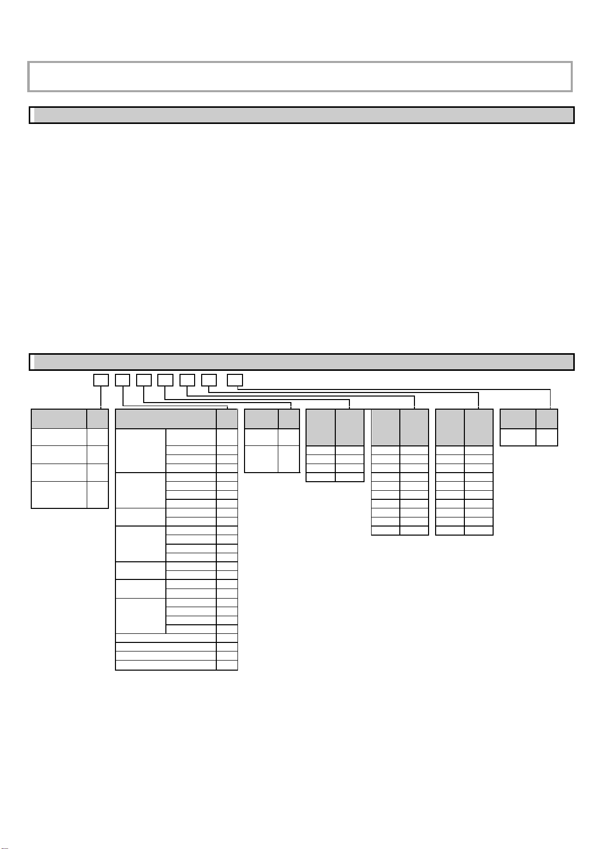
2. ORDER CODES ....................................................................................................................................................................................................4
3. TECHNICAL DATA ...............................................................................................................................................................................................5
3.1. Explosion Protection, Designation, Limit Values ..........................................................................................................................................7
3.2. Accessories...................................................................................................................................................................................................7
3.3. Conditions for Safe Use................................................................................................................................................................................7
3.4. Maintenance and Repair...............................................................................................................................................................................7
4. INSTALLING .........................................................................................................................................................................................................8
4.1. Handling and Storage ...................................................................................................................................................................................8
4.2. Mounting on Containers................................................................................................................................................................................8
4.2.1. General mounting instructions .................................................................................................................................................................8
4.2.2. Installing the Device for Measuring Solids.............................................................................................................................................10
4.3. Wiring..........................................................................................................................................................................................................11
4.3.1. BUS (HART®) communication ...............................................................................................................................................................12
4.4. Switching On and Commissioning..............................................................................................................................................................12
4.5. Available User Interfaces............................................................................................................................................................................12
5. PROGRAMMING.................................................................................................................................................................................................13
5.1. Programming with HyView..........................................................................................................................................................................13
5.1.1. Installing and Running HyView ..............................................................................................................................................................13
5.1.2. Programming and Configuring the Device.............................................................................................................................................13
5.1.3. Programming Example 1 (Using HyView):.............................................................................................................................................18
5.2. Programming with the VGF-DISPLAY: Display Unit...................................................................................................................................19
5.2.1. VGF-DISPLAY: Display Unit ..................................................................................................................................................................19
5.2.2. The Behavior of the VF05 while Programmed Manually .......................................................................................................................19
5.3. Properties of VF05 Two-Wire Microwave Level Transmitter ......................................................................................................................21
5.3.1. Level Measurement –Level reflection, Threshold Line and Automatic Gain Adjustment .....................................................................21
5.3.2. To illustrate the five possible configurations, the following fluid level measurement settings are assumed .........................................22
5.3.3. Echo Loss Handling ...............................................................................................................................................................................22
5.3.4. Typical Signal Forms..............................................................................................................................................................................24
5.4. Troubleshooting ..........................................................................................................................................................................................25

4 / 27
Thank you for choosing a HYCONTROL instrument.
We are sure that you will be satisfied throughout its use!
1. INTRODUCTION
Application
The VF05 two-wire guided microwave level transmitter is used to measure the distance, level, and volume of liquids, solids, and granules. The device can be used in
storage and reaction tanks, rigid pipelines of suitable diameter, and level reference vessels. The device is HART capable, it can be programmed using HyView software
or PACTWARE.
Operating Principle
The VF05 two-wire guided-microwave level transmitter measurement method is based on TDR (Time Domain Reflectometry) analysis of the electromagnetic pulse
traveling along the probe. The device sends nanosecond-wide, low-power pulses along an electrically conductive rod, cable, or coaxial supply line at a known rate of
light propagation speed. If the electromagnetic pulse propagating along the conductor reaches a medium boundary with a different (r) dielectric constant (the surface
of the measured medium or the phase boundary of two liquids), some of the energy is reflected from there. The larger and sharper the (r) dielectric constant change
at the boundary of the media, the better the efficiency of the reflection (e.g., 80% of the energy is reflected from a flat air-water boundary) is.
The pulse is detected and processed by the device as a voltage signal. Since the propagation speed is known, the distance of the reflecting surface can be determined
by measuring the travel time of the pulse. The travel time is the time between the start of the pulse and the arrival of the reflected pulse, and the distance traveled is
twice the distance to and from the target. The device calculates the distance from the measured time into an electric signal proportional to the distance, an output
current of 4…20 mA, and provides a HARToutput signal and displays it on the display. Other derived quantities (volume, weight, etc.) can also be obtained from the
distance data using the device software. The advantage of the described measurement technology compared to other level measurement methods is that the dust,
foam, steam, boiling, and surface turbulence have no disturbing effect.
2. ORDER CODES
VF05
-
-
2-wire guided microwave level transmitter
Version /
Temperature
Code
Probe / Process connection
Code
Housing
Code
Probe
length
(x 10m)
Code
Probe
length
(x 1m)
Code
Probe
length
(x 0.1m)
Code
Output
Code
Transmitter
T
Coaxial
1" BSP
A
Aluminum
7
4…20 mA
+ HART
4
High-temperature
transmitter
H
1" NPT
B
Stainless
steel
9
0 m
0
0 m
0
0 m
0
1½" BSP
C
10 m
1
1 m
1
0.1 m
1
Transmitter +
display
B
1½" NPT
H
20 m
2
2 m
2
0.2 m
2
Rod
1" BSP
R
30 m
3
3 m
3
0.3 m
3
High-temperature
transmitter +
display
P
1" NPT
P
4 m
4
0.4 m
4
1½" BSP
S
5 m
5
0.5 m
5
1½" NPT
Z
6 m
6
0.6 m
6
Dual rod
1½" BSP
D
7 m
7
0.7 m
7
1½" NPT
E
8 m
8
0.8 m
8
4 mm cable
1" BSP
K
9 m
9
0.9 m
9
1" NPT
L
1½" BSP
V
1½" NPT
W
8 mm cable
1½" BSP
N
Note max probe lengths differ: -
1½" NPT
J
Max cable length is 30m
4 mm
dual cable
1½" BSP
T
Max length of Rod & Dual rod (both Ø8mm) is 3m
1½" NPT
U
Max length of Rod (Ø14mm) & Coaxial is 6m
4 mm FEP-
coated cable
1" BSP
F
1" NPT
G
DN40 TriClamp
X
DN40 Milch
Y
Fully PFA-coated rod / DN50
Q
4 mm fully FEP-coated cable / DN50
M
Fully PP-coated rod / DN50
I
Fully PFA-coated rod / 1½" TriClamp
O

5 / 27
3. TECHNICAL DATA
GENERAL
With aluminum housing
VF05–7–4, 5, 6, 8
With stainless steel housing
VF05–9–4, 5, 6, 8
Input
data
Measured values
Distance between the reference point and the plane of the reflection (surface of the material); derived values: level, volume or weight
Measuring range
Depends on the probe and the measured medium (refer to technical data and probes table)
Probe types and technical data
Coaxial, dual cable, cable, dual rod, and rod probes (for technical data refer to the Technical Data of Probes table)
Housing
Cast aluminum with epoxy finish
Stainless steel
Process temperature
–30…+200 °C (–22…+392 °F) (for technical data refer to –MEDIUM TEMPERATURE table –Page 7)
Process pressure
–1…40 bar (–0.1…4 MPa [–14…580 psig]) (for technical data refer to –MEDIUM PRESSURE DIAGRAM –Page 7)
Ambient temperature
–30…+60 °C (–22…+140 °F), with display: –20…+60 °C (–4…+140 °F)
Seal
FPM (Viton), for high temperatures, optional FFKM Perfluoroelastomer (Kalrez6375), EPDM
Ingress protection
IP67
Supply voltage
13…36 V DC, nominal 24 V DC, built-in transient overvoltage protection
Output
data
Output signal
Analog: 4…20 mA; (3.9…20.5 mA) passive output; error signal 3.8 or 22 mA
BUS: serial, HARTinterface, termination resistor maximum 750 Ω
Display: VGF-DISPLAY LCD dot-matrix
Accuracy (2)
Liquids: 5 mm (0.2"). If probe length is ≥ 10 m (L ≥ 33 feet); 0.05% of probe length
Solids: 20 mm (0.8"). If probe length is ≥ 10 m (L ≥ 33 feet); 0.2% of probe length
Wiring
2× M20x1.5 metal cable gland; cable diameter: Ø7…13 mm (Ø0.3…0.5"), or M20x1.5 plastic cable gland; cable diameter: Ø6…12 mm (Ø0.23…0.47")
maximum wire cross section: 0.5…1.5 mm2(AWG20…AWG15) (shielded cable recommended) + internal thread 2× ½" NPT for the cable’s damping tube
Electrical protection
Class III
Weight (housing)
1.3 kg (2.9 lbs)
2.2 kg (4.9 lbs)
3.9 kg (8.6 lbs)
(1) With ideal reflective surfaces and constant temperatures.
TECHNICAL DATA OF PROBES
Type
VF05K––
VF05L––
VF05V––
VF05W––
VF05R––
VF05P––
VF05S––
VF05Z––
VF05N––
VF05J––
VF05T––
VF05U––
VF05D––
VF05E––
VF05A––
VF05B––
VF05C––
VF05H––
Version
4 mm cable (0.15")
Rod
8 mm cable
(0.3")
4mm dual cable
(0.15")
Dual rod
Coaxial
Maximum measuring
range
30 m (100 feet)
3 m (10 feet)
6 m (20 feet)
30 m (100 feet)
3 m (10 feet)
6 m (20 feet)
Minimum measuring
range
r= 80 / 2.4
0.25 m / 0.35 m (9.84” / 13.8”)
0.15 m / 0.3 m (0.5 feet / 1 feet)
0 m (0 feet)
Min. distance to
objects
600 mm (Ø2 feet)
200 mm (Ø 0.65 feet)
0 mm (0 feet)
Minimum rof medium
2.1
1.8
1.4
Process connection
1" BSP
1" BSP
1½" BSP
1" BSP
1" NPT
1" NPT
1½" BSP
1" NPT
1½" NPT
1½" BSP
1½" NPT
1½" NPT
Material of probe
316 (1.4401)
316Ti (1.4571)
316 (1.4401)
316Ti (1.4571)
Nominal diameter of
probe
4 mm (0.15")
8 mm (0.3")
14 mm (0.55")
8 mm (0.3")
4 mm (0.15")
8 mm (0.3")
28 mm (1.1")
Weight
0.12 kg/m
(0.08 lb/feet)
0.4 kg/m
(0.25 lb/feet)
1.2 kg/m
(0.8 lb/feet)
0.4 kg/m
(0.25 lb/feet)
0.24 kg/m
(0.16 lb/feet)
0.8 kg/m
(0.5 lb/feet)
1.3 kg/m
(0.85 lb/feet)
Separator material
–
PFA,
welded onto cable
PTFE-GF25
if length is
>1.5 m (5 feet)
PTFE,
if length is
>1.5 m (5 feet)
Tensioning weight
dimensions
Ø25 x 100 mm (Ø1
x 4")
–
Ø40 x 260 mm
(Ø1.5 x 10")
Ø40 x 80 mm (Ø1.5
x 3")
–
Material of tensioning
weight
316Ti (1.4571)
–
316Ti (1.4571)
316Ti (1.4571)
–

6 / 27
Type
VF05F––
VF05G––
VF05TX––
VF05TY––
VF05TM––
VF05TQ––
VF05TI--
Version
4 mm (0.15") FEP-coated cable
4 mm (0.15") fully
FEP-coated cable
Fully PFA-coated
rod
Fully PP-coated rod
Maximum measuring range
30 m (100 feet)
3 m (10 feet)
Minimal measuring range
r = 80 / 2,4
0.25 m / 0.35 m (9.84” / 13.8”)
Free space requirement
600 mm (Ø2 feet)
Minimal rof medium
2.1
Process connection
1” BSP
DN 40 Triclamp
DN 40 Milch
DN 50
1” NPT
Material of probe
316 (1.4401) / FEP
316Ti (1.4571) /
PFA
316Ti (1.4571) /
PP
Nominal diameter of probe
6 mm (0.23")
12 mm (0.5")
16 mm (0.62")
Mass
0.16 kg/m (0.1 lb/feet)
0.5 kg/m
(0.33 lb/feet)
0.6 kg/m
(0.4 lb/feet)
Coating of fillet and tension
weight
–
PFA
PP
Tensioning weight
dimensions
Ø25 x 100 mm (Ø1 x 4")
–
Material of tensioning
weight
316Ti (1.4571)
–
Maximum medium
temperature
+150 °C (+302 °F)
+60 °C (+140 °F)
MEDIUM TEMPERATURE
MEDIUM PRESSURE DIAGRAM
Type
FLANGE TEMPERATURE
200°C
140°C
80°C
20°C
-30°C -1 bar 16 bar 24 bar 32 bar 40 bar
Base model
–30…+90 °C (–22…+194 °F)
High-temperature HHor HPtransmitter
–30…+200 °C (–22…+392 °F)
DIMENSIONS
VF05TK––
VF05TL––
VF05TV––
VF05TW––
VF05TR––
VF05TP––
VF05TS––
VF05TZ––
VF05TN––
VF05TJ––
VF05TT––
VF05TU––
VF05TD––
VF05TE––
VF05TA––
VF05TB––
VF05TC––
VF05TH––
VF05TF––
VF05TG––
VF05TX––
VF05TY––
VF05TM––
VF05TQ––
VF05TI––

7 / 27
3.1. EXPLOSION PROTECTION,DESIGNATION,LIMIT VALUES
Licensing in progress.
3.2. ACCESSORIES
•Hyview software •2× M20x1.5 cable gland
•User and Programming manual •VGF-DISPLAY display unit (option)
3.3. CONDITIONS FOR SAFE USE
▪The metal housing of the device must be connected to the equipotential (EP) network.
▪The aluminum content of the cast aluminum housing exceeds the limit value, so the equipment must be protected against impact and friction.
3.4. MAINTENANCE AND REPAIR
VF05 does not require maintenance on a regular basis. In some very rare instances, however, the probe may need cleaning to remove deposited material.
This must be carried out gently, without damaging the probe. Repairs during or after the warranty period are carried out exclusively at the Manufacturer. The
equipment sent back for repair should be cleaned or disinfected by the User.

8 / 27
4. INSTALLING
4.1. HANDLING AND STORAGE
Lift the instrument using both hands, or if necessary, use a hoist. Do not lift the instrument
by the probe. It is a critically sensitive part.
Protect the instrument from mechanical impacts and falling. The electronics
is a sensitive and fragile unit.
Do not bend coaxial and rod probes.
The device must be supported in the marked places.
The cable probe must not be looped, broken, or frayed.
The minimum bending diameter is 0.4 m (16″).
All these may cause a measurement error.
Storage temperature:
4.2. MOUNTING ON CONTAINERS
4.2.1. General mounting instructions
The size and position of the connector on the top of the tank (and the distance from the wall), the internal anti-reflection fittings, the rough joints, the welds and the
shape and design of the top and bottom of the tank are very important for the correct operation of the device. Any factor that affects the formation of the electromagnetic
field of the probe also significantly impairs the measurement accuracy. The coaxial probe is an exception because it has no external electromagnetic field.
Threaded process connection
Lifter height
Lifter intrusion into the tank
The easiest way to mount onto the tank is with a
device screwed into a 1 "BSP, 1" NPT, 1½ "BSP
or 1½" NPT threaded hole.
Do not use a lifter longer than the probe diameter
for individual probes and dusty applications.
h ≤ Ød, where
h = lifter height
Ød = lifter diameter
Consult HYCONTROL if the above condition cannot
be met!
The lifter must not extend into the tank,
as the protruding part interferes with the
measurement!

9 / 27
Mounting two devices
Effects of material influx
Using a protective tube
If two devices have to be mounted on one
tank, they must be spaced at least 2 m
(6.5 ft) apart to eliminate interference and
measurement inaccuracies resulting from
the interaction of the two electromagnetic
fields.
Devices equipped with coaxial probes are
not subject to the above warning because
there is no electromagnetic field outside the
probe's outer sheath.
Do not place the lifter near the material inlet
pipe connector.
Material flowing onto the sensor probe causes
incorrect level indication. If there is not enough
space, it is recommended to install a baffle plate.
The floating lid is a common solution for petrochemicals. In
such cases, the use of a damping tube is recommended.
Straightness and contact of measuring probes
with other fittings and distance from the bottom of the tank.
Using a stirrer
After installation, the cable probes and the associated tensile weight
must be straight, tensioned, and away from other fittings (e.g.,
mixer). They must not come into contact with the tank wall, bottom,
or other objects.
The installation space requirements of the different measuring
probes must be taken into account according to the data of the
measuring probes (see Technical Data).
There is no radiation cone along the probe.
When measuring liquids, the use of a reference chamber or damping tube is
recommended, since it provides mechanical and electromagnetic protection for accurate
measurement.
Protect the device from direct sunlight!
Attaching the probe to the bottom of the tank.
Flexible cable probes can be anchored to the bottom of the tank with a fastener or loop.
Installing and shortening the cable probes
If necessary, the probe can be shortened, but only for liquid applications.
Steps:
1. Loosen the grub screws (hexagon) with an Allen key. (ISO 2936)!
2. Pull the cable out of the tension weight and cut to the desired size!
3. Insert the cable back into the weight as shown and tighten the screws!
4. Modify the configuration parameters to the new length, the reference point being the
upper edge of the weight!

10 / 27
4.2.2. Installing the Device for Measuring Solids
False measured value
Coning and strong tensile force on the probe
The probe may not touch the lifter pipe
Strong tensile force. The rope must not be
anchored when measuring solids.
The device is mounted at a distance of half the
radius of the tank from the top of the tank with a
minimum lift nozzle height.
It prevents excessive mechanical stress when
emptying the tank.
The tensile force of the probe rope depends on the height and shape of the
tank, the fragmentation of the material, the density, and the speed of
discharge.
The following table gives the tensile load values for the different materials
(approximate data in tons).
Probe type
Material
Probe length
6 m
(20 ft)
12 m
(40 ft)
24 m
(80 ft)
Single cable, Ø8 mm (Ø0.31″), max. load: 3.0 T
Cement
0.6 T
1.2 T
2.4 T
Ash
0.3 T
0.6 T
1.2 T
The measured process material can accumulate on the probe and lifter, which weakens the energy of the measuring pulse.
Avoid creating cavities that increase deposition.
Observe the load capacity of the tank top, which must ensure the maximum tensile force of the probe.

11 / 27
4.3. WIRING
Wiring in non-explosive environments
1. Take the device’s lid off.
2. Put the cable through the cable gland (½" NPT) to the terminal block.
3. Remove the outer insulation for ~80 mm (~3.15″) from the cable so the wires can be accessed, then strip the
wires for 4 mm. Strip the shielding from the signal cable.
4. Connect the cable to terminal 2 and 3 (polarity is irrelevant).
5. Retract the cable so the cable’s outer insulation runs through the cable gland for about 10 mm (0.4″). Then
tighten the cable gland’s nuts with two wrenches.
6. Organize the wires in the compartment.
7. Put the lid back on.
Do not perform insulation tests with a test voltage of 500 V AC on the device due to the internal electronic
surge protection!
Connecting (grounding) to equipotential network (EPH)
Electrostatic discharge (E.S.D.)
Threaded earth connection (EP) on the side of the housing,
maximum wire cross section: 4 mm² (AWG12). The housing of
the device must be earthed to a ground with a resistance of
R1 Ω.
The shield of the test lead must be earthed at the instrument
panel. Do not run the test lead near high-current cables, as
shielding does not provide protection against switching
harmonics.
The device is protected against 4 kV ESD.
Warning: The electrostatic discharge protection of the
measuring system cannot be solved by the internal ESD
protection.
In all cases, it is the user's responsibility to ensure that the
tank, measured material, and probe are grounded.
Risk of injury!
The probe may accumulate an electrostatic charge during
regular operation, so discharge it to the ground by touching
it (tank side) when installing!
Ground the inlet and the measured medium!
Design of the measuring network in non-explosive environments
Power supply
Nominal voltage
24 V DC
Maximum voltage (Uin):
36 V DC
Minimal voltage (Uin):
Depends on the impedance. (See diagram)
Loop resistance, Rloop
RHART + Rcable + Rammeter
Minimum RHART
0 Ω
Maximum RHART
750 Ω
RHART resistance for HART®communication
250 Ω (recommended)
Line A: minimum voltage on the device’s input terminals
Line B: minimum supply voltage (voltage drop on the device and the 250 Ω loop
resistance)
An example for calculating the supply voltage:
The minimum supply voltage at Imin = 4 mA current:
Usupply min.= Uin min.+ (Imin * loop resistance) = 12 V + (4 mA * 0.25 kΩ) = 13 V
The minimum supply voltage at Imax = 22 mA current:
Usupply min.= Uin min.+ (Imin * loop resistance) = 11.5 V + (22 mA * 0.25 kΩ) = 17 V
Therefore, if the loop resistance is 250 Ω, 17 V is just enough for the entire 4…20 mA
measuring range.

12 / 27
4.3.1. BUS (HART®) communication
The output of the device can be used in two ways: 1. Current loop output and HART®2. Passive, HART®protocol
The HyView program supports the use of both modes.
According to the Rosemount Standard, HART®communication can be used as a point-to-point connection between VF05 as a “slave” and a HART®“master”.
There are two modes of communication:
•If the device (HART®short address 0) is set to current loop transmission (4…20 mA), only one device can be in the HART®communication loop
•For multidrop operation (4mA), several devices (max. 15) can be connected to one HART®communication loop. In this case, a short address other than 0
must be set for the device.
4.4. SWITCHING ON AND COMMISSIONING
The VF05 two-wire device is supplied by HYCONTROL with the technical specifications requested by the customer, so it is ready for operation immediately after
installation and wiring up.
Measuring starts less than 20 seconds after switching on. Attention! The initial current consumption of the device is 3.5 mA right after switching on! If there is
a change in the installation data due to shortening a cable probe, the set parameters must be changed according to the application before starting the measurement.
4.5. AVAILABLE USER INTERFACES
The instrument can be programmed by using the following devices / accessories:
VGF-DISPLAY display unit
Ordered separately. See ”5.2. Programming with the VGF-DISPLAY display unit.”
Hyview software (PC needed)
Available as download
HART®Microlink USB modem
Ordered separately. See ”5.1. Programming with HyView”

13 / 27
5. PROGRAMMING
There are two ways to program the VF05.
−Programming with the HyView software
−Programming with the VGF-DISPLAY display unit
5.1. PROGRAMMING WITH HYVIEW
5.1.1. Installing and Running HyView
If necessary, install the “HyView HART Configuration Software” (hereafter HyView).
Electrical connections: Connect the transmitter to a PC using a HARTUSB modem (sold separately).
Start the program and search for the transmitter in the program.
5.1.2. Programming and Configuring the Device
Select the device from the list of found devices to configure and program and open the device's "Device Programming" window.
All the necessary parameters and function settings can be performed with HyView. The table below summarizes the parameters and their location and path.
5.1.2.1 Parameters
Table 1.
Name (number), function
Adjustable value range
Description
Default value
Zero-level distance (P04),
Set container height
0...60 m
(0…200 ft)
It provides the basis for level measurement calculations. The distance between the plane of the lower
sealing surface of the mechanical connector (the lower plane of the flange in the case of a flanged
version) and the reference point at the bottom of the tank. Its value must be set in a distance unit (Unit
- P00b).
Note: There is no measurement beyond the set zero distance if the output is configured for distance or
level measurement.
HyView setting: “Device Settings” > “Measurement configuration” > “Zero-level dist.”
VGF-DISPLAY:
MAIN MENU / CALCULATION / ZERO-LEVEL DISTANCE
As per order
Minimum measuring distance
(P05),
Dead zone
Warning!
Critical parameter!
Minimum measuring distance… probe
length (P03)
The dead zone is the distance between the plane of the lower sealing surface of the mechanical
connection (the lower plane of the flange in the case of the flanged version) and the highest level in the
tank. Signals generated within the dead zone are not processed. The current loop output does not follow
the dead zone level signal. Its value must be set in distance units (Length unit –P00b).
HyView setting: “Device Settings” > “Measurement configuration” > “Minimum”.
VGF-DISPLAY:
MAIN MENU / MEASUREMENT CONFIG / MIN. MEAS. DIST.
“Minimum measuring distance”
according to the Probe data table
Maximum measuring range limit
(P06),
Remote blocking
0 (limiter off) or the minimum measuring
distance. The distance between (P05) + 5
cm and the probe length (P03)
The maximum value of the measuring range of the device can be limited with this parameter. Signals
received beyond the set distance will not be processed. Its value is calculated from the plane of the
lower sealing surface of the mechanical connector (in the case of a flanged version, from the lower
plane of the flange).
Remote blocking can be turned off by setting the parameter to 0. In this case, the device will give a
valid result along the entire length of the sensor.
HyView setting: “Device Settings” > “Measurement optimalization” > “Far end (P06)”.
VGF-DISPLAY:
MAIN MENU / MEASUREMENT CONFIG / MAX. MEAS. DIST.
0
(off)
Damping time (P20)
Time constant
0…999 sec.
The "Damping time" is used to reduce undesired fluctuations (e.g.: rippling) in the display of the
measured data. If the level changes abruptly, the new value will be set to within 1% accuracy
(exponential setting). Unit of measure: seconds.
HyView setting: “Device Settings” > “Measurement optimalization” > “Damping time”
VGF-DISPLAY:
MAIN MENU / MEAS. OPTIMIZATION / DAMPING TIME
10 sec
Probe length (P03)
0.1…30 m
(0.33…100 ft)
The set value is the nominal probe length + 100 mm (+ 0.33 ft).
This value should only be changed if the probe length is changed or the probe is replaced.
Its value must be set in distance unit (Length unit - P00b). For special applications, the length of the
probe may be greater than the height of the tank but may not exceed 30 m (100 ft).
HyView setting: “Device Settings” > “Measurement configuration” > “Probe length settings”
VGF-DISPLAY:
MAIN MENU / MEASUREMENT CONFIG / PROBE LENGTH
Default probe length as per order
+ 0.1 m (+ 0.33 ft)
Fixed output current (P08),
Setting constant output current
3.8…22 mA
When the current output is set to "Fixed" mode (P12b = 1), the constant current set here is set. The PV
current transmission does not work, and at the same time, it overrides any current output fault indication.
HyView setting: “Device Settings” > “Outputs” > “Fix output current (P8)”
VGF-DISPLAY:
MAIN MENU / OUTPUT SETUP / ANALOG OUTPUT / MANUAL VALUE
4
System of measurement units,
units of measurement:
Path of parameters:
“Settings” / Application” tab
Unit system (P00c),
Unit system settings
Selectable values:
−Metric (EU),
European unit system
−Imperial (US),
US unit system
The units that can actually be used (length, volume, weight) change according to the unit system set
according to this parameter. When setting or changing units, the unit system must be selected first and
only then can the actual unit to be used be set (according to the previously narrowed list).
HyView setting: “Device Settings” > “Application” > “Calculation system”
VGF-DISPLAY:
MAIN MENU / BASIC SETUP / UNITS / ENGINEERING SYSTEM
Metric (EU)

14 / 27
Name (number), function
Adjustable value range
Description
Default value
Distance unit (P00b),
Length unit
Selectable values
Metric (EU):
−m
−cm
−mm
−custom unit
Imperial (US):
−inch
−ft
The unit of measurement for the transmitter when the distance and level are set.
If “custom unit” is selected, the unit uses the unit of length as the distance unit based on the value
specified in “User Unit.”
HyView setting: “Device Settings” > “Application” > “Engineering units”
VGF-DISPLAY:
MAIN MENU / BASIC SETUP / UNITS / ENGINEERING UNITS /
DISTANCE UNITS
m
Output unit,
volume (P02b)
Volume unit
Selectable values
Metric (EU):
−liter
−hl
−m3
−million liters
Imperial (US):
−gallon
−ft3
−barrel
−million gallons
The unit of the transmitted number when set to volume measurement. The device converts the
measured level into volume by calculation.
It is done by using a level-dependent (non-linear) function.
It also gives the unit of measure for the “Output” column in the VM table (OC).
HyView setting: “Device Settings” > “Measurement configuration” > “Volume units”
VGF-DISPLAY:
MAIN MENU / BASIC SETUP / UNITS / ENGINEERING UNITS /
VOLUME UNITS
IT IS ONLY DISPLAYED IF THE PV IS VOLUME!
liter
Output unit,
Weight (P02a)
Weight unit
Selectable values
Metric (EU):
−kg
−ton
−US ton
Imperial (US):
−lb
−US ton
−metric ton
The unit of the transmitter number if the device is set for weight measurement. The device converts the
measured level into weight.
It is done by using a level-dependent (non-linear) function.
It also gives the unit of measure for the “Output” column in the VM table (OC).
HyView setting: “Device Settings” > “Measurement configuration” > “Mass units”
VGF-DISPLAY:
MAIN MENU / BASIC SETUP / UNITS / ENGINEERING UNITS /
MASS UNITS
IT IS ONLY DISPLAYED IF THE PV IS MASS!
kg
Operating mode (P00a),
Measured medium property
Selectable values:
−Liquid
−Granular solid
−Two interfacing liquids
The basic characteristic of the measured medium is set here. The measuring capabilities of the device
vary significantly depending on this characteristic of the medium (see specification).
HyView setting: “Device Settings” > “Application” > “Operating mode”
VGF-DISPLAY:
MAIN MENU / BASIC SETUP / APPLICATION
Liquid medium
Unit system (P00d),
Temperature unit
Selectable values:
−°C
−°F
The unit of temperature measurement is selected here.
HyView setting: “Device Settings” > “Measurement configuration” > “Temperature”
VGF-DISPLAY:
MAIN MENU / BASIC SETUP / UNITS / ENGINEERING UNITS /
TEMPERATURE UNITS
°C
Output function (P01ab),
Application mode
Selectable values
Metric (EU):
−Distance
−Level
−Volume
−Mass
−Ullage volume
Set the physical quantity for the transmitted meter. The device measures distance. The other
quantities are calculated based on the specified tank parameters and material characteristics.
HyView setting: “Device Settings” > “Measurement configuration” > “Measurement mode (PV
source)”
VGF-DISPLAY:
MAIN MENU / MEASUREMENT CONFIG / PV. MODE
LEVEL
Custom Unit multiplier (P07)
User defined unit
(Length unit)
0.001…100
The distance in "custom unit" is the distance in meters multiplied by P07 to get. The corresponding
setting field only appears or is active if "custom unit" is selected in the unit system.
The reference of the multiplier is meter, the value of the conversion factor must always be given in
relation to it.
For example, if the conversion factor is 10, then the new unit is 10 m (33 ft) or if the conversion factor
is 0.1, the new unit is 0.1 m.
HyView setting: “Device Settings” > “Application” > “Conversion factor”
VGF-DISPLAY: no adjustment available
1.000
Select echo (P25)
Selectable values:
−Highest amplitude
−First
−Second
−Last
In problematic cases, it is possible to choose between the echoes created during the measurement in
order to ensure a stable measurement and transmission.
HyView setting: “Device Settings” > “Measurement optimalization” > “Selection of Echo…”
VGF-DISPLAY: no adjustment available
Highest amplitude
Filling speed (P26)
0.1…900m/h (0.33…2950 ft/h)
The maximum rate of rise in the tank during filling. Entering it correctly increases the reliability of the
measurement during charging.
HyView setting: “Device Settings” > “Measurement optimalization” > “Level elevation rate …”
VGF-DISPLAY: no adjustment available
900m/h (2950 ft/h)
Emptying speed (P27)
0.1…900m/h (0.33…2950 ft/h)
The maximum rate of dropping in the tank during emptying. Entering it correctly makes the
measurement more reliable during emptying.
900m/h (2950 ft/h)

15 / 27
Name (number), function
Adjustable value range
Description
Default value
HyView setting: “Device Settings” > “Measurement optimalization” > “Level descent rate …”
VGF-DISPLAY: no adjustment available
Current output, current output
signal settings:
Path to parameters:
“Device settings” / Outputs” tab
Current loop output (P12b),
Set mode
Selectable values:
−Auto
−Manual
Selects the current loop output mode when transmitting current. In “Auto” mode, the output current
changes proportionally to the PV (4… 20 mA). In the case of “Manual,” the constant current set in the
parameter P08 is forced to the current output mainly for testing purposes.
HyView setting: “Device Settings” > “Outputs” > “Current generator mode”
VGF-DISPLAY:
MAIN MENU / OUTPUT SETUP / ANALOG OUTPUT / CURRENT MODE
Auto
Current loop output (P12a),
Value of output current if there is
an error (error current)
Selectable values:
−Hold
−3.8 mA
−22 mA
This parameter determines the state that the current loop output draws in the event of a fault. For “Hold,”
it keeps the last measured value (4… 20 mA), for “3.8 mA” and “22 mA” it keeps the indicated value until
the fault is present.
HyView setting: “Device Settings” > “Outputs”> “Current output -> Error indication by the current
output”
VGF-DISPLAY:
MAIN MENU / OUTPUT SETUP / ANALOG OUTPUT / ERROR MODE
Hold
Value assigned to 4 mA
(P10)
Selectable values:
In accordance with the PV adjustment
range, usually minimum value
PV value assigned to 4 mA in current transmission mode (usually the lower limit of the measuring
range for level measurement).
HyView setting: “Device Settings” > “Outputs” > “Assignment of 4 mA - PV”
VGF-DISPLAY:
MAIN MENU / OUTPUT SETUP / ANALOG OUTPUT / 4mA VALUE
0.000 m (0.000 ft)
Value assigned to 20 mA (P11)
Selectable values:
In accordance with the PV adjustment
range, usually maximum value
PV value assigned to 20 mA in current transmission mode (usually the upper limit of the measuring
range for level measurement).
HyView setting: “Device Settings”> “Outputs” > “Assignment of 22 mA - PV”
VGF-DISPLAY:
MAIN MENU / OUTPUT SETUP / ANALOG OUTPUT / 22mA VALUE
6.000 m (20.000 ft)
Echo loss handling (P28b),
Error signal delay
Selectable values:
No delay
−10 sec
−20 sec
−30 sec
−1 min
−2 min
−5 min
−15 min
This parameter determines the time elapsed between the occurrence of the fault and the error signal (e.
g.: fault current). The output is held at the time of the delay, based on the last valid measured data. The
function is only available for current output with an error signal set to the lower (3.8 mA) or the upper
(22 mA) error current.
HyView setting: “Device Settings” > “Measurement optimalization” > “Error delay”
VGF-DISPLAY: no adjustment available
0
(no delay)
Special, identifying data
Path to parameters:
“Device programming window (Advanced mode) / Special” tab
HART short address (P19),
Device address
0…15
Unique device address based on which the device can be identified and managed via the HART bus.
•0: analog output active (current loop transmission active, 4…20 mA)
•1…15: analog output inactive (no current loop transmission, constant 4 mA), Multidrop
HyView setting: “Device Settings” > “Device identification” > “Device short address”
VGF-DISPLAY:
MAIN MENU / OUTPUT SETUP / SERIAL OUTPUT / ADDRESS
0
RELAY mode (P13a),
RELAY output modes
Selectable values:
−OFF
−PV
−On Error
The operating mode of the RELAY with optional level switching functions can be set with this parameter.
The function is Off by default. When set to “PV,” the RELAY operates based on the trigger and release
values set according to the PV. The “On Error” setting allows a switched (relay contact) fault indication
to the process controller.
HyView setting: “Device Settings” > “Outputs” > “Relay mode”
VGF-DISPLAY:
MAIN MENU / OUTPUT SETUP / RELAY OUTPUT / RELAY MODE
OFF
RELAY mode (P13b),
RELAY functions
Selectable values:
−Hysteresis
−Window comparator
The basic switching methodology of the RELAY set to “PV” mode can be set.
HyView setting: “Device Settings” > “Outputs” > “Relay function”
VGF-DISPLAY:
MAIN MENU / OUTPUT SETUP / RELAY OUTPUT / RELAY FUNCTION
Hysteresis
RELAY mode (P13c),
RELAY inverted mode
Selectable values:
−Not inverted
−Inverted
If the setting is non-inverted, the RELAY closes its contacts when the trigger value is reached, otherwise
(inversion) opens these contacts.
HyView setting: “Device Settings” > “Outputs” > “Relay inverted”
VGF-DISPLAY:
MAIN MENU / OUTPUT SETUP / RELAY OUTPUT / INVERTING
Not inverted
RELAY trigger value (P14)
Value can be adjusted in accordance with
PV setting interval
The measured PV value at which reaching the upper limit (upper switching value) is signaled on the
RELAY output.
HyView setting: “Device Settings” > “Outputs” > “Energized value”
VGF-DISPLAY:
MAIN MENU / OUTPUT SETUP / RELAY OUTPUT / ENERGIZED VALUE
1.000 m (3.300 feet) (level)
RELAY release value (P15)
Value can be adjusted in accordance with
PV setting interval
The measured PV value at which reaching the lower limit (lower switching value) is signaled on the
RELAY output.

16 / 27
Name (number), function
Adjustable value range
Description
Default value
5.000 m (16.400 ft) (level)
HyView setting: “Device Settings” > “Outputs” > “De-Energized value”
VGF-DISPLAY:
MAIN MENU / OUTPUT SETUP / RELAY OUTPUT / DEENERGIZED VALUE
RELAY delay (P16)
0…999 sec
In the event that the PV measured value has reached the lower or upper switching value or an error
signal has occurred in the event of an error, the RELAY is activated and a change is visible on the
relay output after this time delay.
HyView setting: “Device Settings” > “Outputs” > “Relay delay time”
VGF-DISPLAY:
MAIN MENU / OUTPUT SETUP / RELAY OUTPUT / DELAY
0 sec
Tank type (P40a),
Tank shapes for volume
measurement
Selectable values:
−Output Conversion table (OCT)
−Standing cylindrical tank with dome
bottom
−Standing cylindrical tank with
conical bottom
−Standing rectangular tank with or
without chute
−Lying cylindrical tank
−Spherical tank
Selecting a typical basic container shape for volume measurement. The tank dimensions can be set
using parameters P41… P45 (see figures below). If OCT is set, the tank shape must be specified in
tabular form.
HyView setting: “Device settings” > “Tank/Silo parameters” > “Tank shape”
VGF-DISPLAY:
MAIN MENU / CALCULATION / TANK SHAPE
IT IS ONLY DISPLAYED IF THE PV IS VOLUME!
Standing cylindrical tank with dome
bottom
Tank type (P40b), Tank
properties for volume
measurement, tank bottom
shape
Selectable values:
−0 (flat)
−1
−2
−3
Assigning typical tank bottom designs to a specific tank type for accurate volume calculation. The
exact form for the setting code is shown in the figure below.
HyView setting: “Device settings” > “Tank/Silo parameters” > “Bottom shape”
VGF-DISPLAY: no adjustment available
0 (flat)
Standing cylindrical tank with dome
bottom
Standing cylindrical tank with
conical bottom
Standing rectangular tank
Lying cylindrical tank
Spherical tank
Tank dimensions (P41…P45), for
volume measurement
0…999 999
Typical dimensions in units of length for the tank type set in parameter P40 for volume calculation.
HyView setting: “Device settings” > “Tank/Silo parameters” > ”Bottom shape”
VGF-DISPLAY: no adjustment available
0
Specific gravity (P32),
for weight measurement
0.01…100
If the device is set to weight measurement, the specific gravity of the material (medium) stored in the
tank must be entered here for weight calculation. The value to be set is the ratio (without unit) to the
density of the water.
HyView setting: “Device settings” > “Measurement optimalization” > “Specific gravity”
VGF-DISPLAY: no adjustment available
Threshold offset (P34), interference
sensitivity setting
-4095…+4095
Modifies the acceptance threshold set on the echo chart. It can be used it to increase (positive value)
or decrease (negative value) the device's ability to suppress the interference signal relative to the
default setting. When set to 0, there is no change from the original setting.
HyView setting: “Device settings” > “Measurement optimalization” > “Threshold offset”
VGF-DISPLAY:
MAIN MENU / MEAS. OPTIMIZATION / THRESHOLD OFFSET
0

17 / 27
User defined multiplier (P22),
Correction factor (measured/actual)
0.7…10
Adjusts the transmitted quantity by distance. If the value measured by the device differs from the
value under real conditions, this multiplier can be used to adjust the result. The output value is
multiplied by the number set here. The default multiplier is 1, which does not change the output.
HyView setting: “Device settings” > “Measurement optimalization” > “Velocity user correction factor”
VGF-DISPLAY: no adjustment available
1
Gross tank volume (P47)
0…999 999
If the output (PV source) is set to “Ullage volume” transmission, the total volume can be specified in
this parameter to calculate the actual transmitted value. In this case, the transmitted data is the
difference between the total volume and the actual volume of the medium. Its unit is PV.
HyView setting: “Device settings” > “Tank/Silo parameters” > ”Total tank volume”
VGF-DISPLAY: no adjustment available
0
5.1.2.2 Setting Up and Filling the OC (Output Conversion) Table
This feature is required to create a level / volume conversion table of up to twenty points. Each new value entered must be greater than the previous one.
The length and volume units can be changed later without changing the data in the table (length unit, volume unit).
The two units on the right and left of the table are given by the length unit and volume unit settings, i.e., these two units must be used to complete the table (length
unit and volume unit).
Important: Volume can only be measured if a conversion table is created!
To fill or adjust the device level / volume table, go to the “Device Setup”> “OC-table” tab in HyView.
Here you can fill or modify the table.
The difference is that if the “Measurement mode PV source” parameter is set to “Volume” or “Ullage Volume”, the OC table is active.
When the appropriate changes have been made to the table or it has been filled in correctly, click the “Send” button under the “Get” button on the right on this page
(“OC-table” tab) to download the table.
5.1.2.3 Device status window
To turn on the “Device status window” in HyView, right-click on the device line in the “Device list” list in the main window and select “Show Device Status Window” in
the popup window.
5.1.2.4 Device “Echo Diagram” (Oscilloscope Function)
Open the “Echo Diagram” window to display the device echo diagram.
The “Device Echo map” window will appear. The diagram shows the reflection curve measured by the device.
Press the “Refresh” button in the bottom row of the window (or press the F4 button while in the window) to refresh the chart or read the data. After a successful
reading, a curve corresponding to the image below will appear on the graph (see Figure 1).
If there was an evaluable level signal, it will also appear on the graph (“Selected peak” bubble window) along with other additional information. In addition, you can
use this window to set any “Threshold” level.
5.1.2.5 Level Threshold
The level threshold of the device can be changed in the echo diagram window, i.e., the value of “Threshold.”
This may be necessary if the device does not find the level signal (e.g., the set level threshold is too high or too low and the gain is already at the highest level).
To change the “Threshold” value, access the “Threshold settings”> “Threshold edit enable” function from the pop-up menu triggered by a right-click. The corner
points of the threshold curve on the echo diagram can then be adjusted with the mouse. Pressing the “Apply Threshold” button on the left help panel will apply the
set threshold value. To refresh the chart, press the “Refresh” button (or press the F4 button in the window).
Attention! The “Cursor On” function does not give an exact
value, it only recalculates the value of the given point based on
the graphical representation.

18 / 27
5.1.3. Programming Example 1 (Using HyView):
Changing the actual tank height (10.000 m [33.000 ft]).
To the probe (cable) length L2 (9.000 m [29.500 ft]) configured by the manufacturer, and saving the new parameter.
Step
Operation
Entered data / value
1
Open the “Device Setup” window for that device in HyView
The program will read and display the device settings
2
Select “Measurement configuration”
3
Click on "Zero-level dist." (Zero-Level Distance)
The data in the field: 10.000 [m] ([33.000 [ft])
4
Enter the new value
9.000 [m] (29.500 [ft])
5
Press the button labeled “Send” in the lower right row of the window to download the new
value to the device
6
Press the “X” close button to exit the device settings window
Programming Example 2 (Using HyView):
Setting custom scale: Select the “Level” measurement mode as the current loop output parameter to set the scale from the bottom of the tank.
Set the current range from 4…20 mA with 22 mA as error signal.
Select the appropriate minimum and maximum values for the measurement scale.
Step
Operation
Entered data / value
1
Open the “Device Setup” window for that device in HyView
The program will read and display the device settings
2
Select “Measurement configuration
3
Within the “Measurement mode PV” section, select the new setting value (Level) from the drop-down
list
This field will read “Level”
4
Select “Outputs”
5
Select “Error indication …” drop-down list.
The field will say “Hold”
6
Select “New setting” from the drop-down list
The field will say “22 mA”
7
Select the data field named “Assignment of 4 mA - PV”.
The field will say “0.000 [m]” (“0.000 [ft]”)
8
Enter the new value.
This gives the level corresponding to a minimum output of 4 mA.
The field will say “1.000 [m]” (“3.300 [ft]”)
9
Select the data field named “Assignment of 20 mA - PV”
The field will say “6.000 [m]” (“20 [ft]”) (default: 6.000 [m])
10
Switch to 8,600 m.
This gives the level corresponding to the maximum output of 20 mA (and sets the maximum output to
the upper limit of the dead zone).
The field will say “8.600 [m]” (“28,2 [ft]”)
11
Press the button labeled “Send” in the lower right row of the window to download the new values to
the device.
12
Press the “X” close button to exit the device settings window.
Creating a volume table –(HyView OC-table (OCT))
A conversion table has to be created using HyView to measure volume.
The volume values in the table are assigned to the measured levels. For asymmetrical and irregularly shaped containers, the accuracy of the volume measurement
depends on the number of pairs of values associated. The maximum number of pairs is 20. The volume is determined by linear interpolation between two value
pairs. The conversion table is usually used for volume measurement, but can also be used for weight or flow measurement.
The following example shows five-point programming.
Here's how to create a user-defined "level-to-volume" conversion table (using HyView).
Step
Operation
Entered data / selected value
1
Open the “Device Setup” window for the device in HyView.
2
Go to “Application” and select “Calculation system”.
Metric (EU), Imperial (US), Optional
Unit
3
Select length (Engineering Unit).
m (ft)
4
Go to “Measurement configuration” and select volume from the “Measurement mode (PV source)” list.
Volume
5
Select the volume unit in “Volume Units”.
m³ (ft³)
6
Go to “Measuring distances”
Enter the tank height into “Zero-level dist.” (click in the field and enter the value).
6.00 m (20 ft)
7
Go to “Probe length” and enter s value for probe length
5.80 m (19 ft)
8
Go to the “Minimum (P5)” field and enter the dead zone value (forbidden distance)
0.40 m (1.3 ft)
9
Press the button labeled “Send” in the lower right row of the window to download the new values to the device.
Please wait while the download process
is complete
10
Go to “OC-Table”
Fill in the table called “OCT list” with the appropriate values.
A maximum of 20 points can be entered. Each level and volume point must be entered.
Each subsequent point must be larger than the previous one.
New lines can be created by pressing Ctrl + Insert, or by selecting “Add new item” in the right mouse button popup menu.
Lines can be deleted by pressing Ctrl + D.
See the following table
(Table 2)
11
To download the spreadsheet to your device, press the “Send” button on the right side of the tab (OC-table) below the “Get”
button.

19 / 27
Table 2. (Input table)
Point
Level (Source column)
Volume (Output column)
Note: The level can be measured effectively between 0.20 m (0.66 ft) and 5.60 m (18.5 ft).
When the level of the measured material falls below the end of the measuring probe, the device
will still indicate 0.20 m, because the level meter can only display between 0.20 m (0.66 ft) and
5.60 m (18.5 ft) according to the probe length (which is now 5.8 m [19 ft]).
The size of the dead zone depends on the equipment and the type of probe.
1
0.0 m (0.0 ft)
0.0 m³ (0.0 ft³)
2
0.20 m (0.66 ft)
0.5 m³ (17.65 ft³)
3
0.75 m (2.5 ft)
1.0 m³ (35 ft³)
4
1.00 m (3.3 ft)
1.5 m³ (52.9 ft³)
5
5.60 m (18.5 ft)
16.8 m³ (593.3 ft³)
Additional procedure for displaying 4… 20 mA current output (using HyView)
Step
Operation
Entered data / Selected value
1
Go to “Outputs” and set “Current generator mode” to “Auto” (default)
Auto
2
Set the error status to the appropriate mode in “Error indication …” (default).
Hold
3
Select the “Assignment of 4 mA - PV (P10)” field and enter the min. volume value for the 4 mA output current.
0.5 m³ (17.65 feet³)
4
Go to the “Assignment of 20 mA– PV (P11)” field and enter the max. 20 mA output current value.
16.8 m³ (593.3 feet³)
5
Press the button labeled “Send” in the lower right row of the window to load the new values into the device
6
Press the “X” close button to exit the device settings window.
5.2. PROGRAMMING WITH THE VGF-DISPLAY: DISPLAY UNIT
The most important parameters of VF05 can also be set with the VGF-DISPLAY: display unit.
By default, the display shows the primary measurement result (from which the output current is calculated).
In addition to the measured value displayed in large numbers, a bar graph representing the value of the output current is also shown on the right.
Programming is done using a text menu. You can use the
E
/ / / buttons to navigate the menu.
5.2.1. VGF-DISPLAY: Display Unit
Display
64 × 128 dot matrix LCD, signs, units and bar graph
Ambient temperature
–20…+60 °C (–4…+140 °F)
Housing material
PBT fiberglass, plastic (DuPont)
The plug-in module containing the VGF-DISPLAY: LCD display (universal - can also be used in other HYCONTROL
devices, provided the device software supports VGF-DISPLAY:).
Warning!
The VGF-DISPLAY: uses an LCD, do not expose the VGF-DISPLAY: to prolonged exposure to strong heat or sunlight as
the display may be damaged.
If the VF05 cannot be protected against solar radiation not possible or it is used outside the operating temperature
range of the VGF-DISPLAY:, do not leave the VGF-DISPLAY: in the VF05!
5.2.2. The Behavior of the VF05 while Programmed Manually
By default, VF05 displays the main measurement data on the VGF-DISPLAY: display (hereafter referred to as display).
Enter the programming menu by pressing the
E
button. Use the / buttons to navigate through the menu items.
Enter the selected menu item with the
E
button. Return to the previous menu level with the key.
The buttons only work if the VGF-DISPLAY: is present!
The device continues measuring while the menu is accessed. Changes made in the menu take effect when you exit the menu.
If you do not exit the VF05 menu, the device will automatically return to the measurement display state after 30 minutes. In this case, any changes made in the menu
will be ignored.
If the VGF-DISPLAY: is pulled out of the VF05, the VF05 will automatically exit the menu and ignore any changes made in the menu.
Since programming with VGF-DISPLAY (manual programming) and remote programming on HART (REMOTE MODE) create a conflict, only one mode can be used
at a time.
Manual programming has priority overt HART!
During manual programming, the device sends a “device is busy” signal to the HART master (HART Response code: 32 – Device is busy).
In remote programming mode, REM is displayed on the top right of the display. In this case, manual programming of the device is disabled, the menu cannot be
accessed.
If no VGF-DISPLAY: is connected, the LEDs will be visible, the flashes of the COM LED will indicate HART communication, and the VALID LED will indicate if the
data measured by the device is valid.
5.2.3. Manual Programming
Press the
E
button to modify the parameter under the cursor in the submenu.
There are two modes: Text list: Navigated is same as in the menu.
The
E
button executes the selection, and the button cancels it.
Editable number field: Serves to edit numeric values.
Editing is aided by an (inverted) cursor.
The number under the cursor can be changed with the / buttons (no overflow).
The cursor can be moved left with the arrow (max. 9 character-positions, including the decimal
point).
When the end of the field is reached, the cursor returns to the first position on the right.
Editing is concluded by pressing the
E
button.
In this case, VF05 will check the entered value and if it is not correct, “WRONG VALUE!” is
displayed in the bottom row.

20 / 27
Menu hierarchy
Other manuals for VF05
1
Table of contents
Other Hycontrol Transmitter manuals