EDS 3400 3
Status: 2018-07-30 HYDAC INTERNATIONAL GMBH Part No.: 670000 E
1 Safety Information
Before commissioning, check the instrument and any accessories supplied. Before
commissioning, please read the operating instructions. Ensure that the unit is suitable for
your application.
Keep the manual in the vicinity of the instrument for immediate reference. Please note that
the specifications given in this documentation regarding the instrument technology were
correct at the time of publishing. Modifications to technical specifications, illustrations and
dimensions are therefore possible.
If the instrument is not handled correctly, or if the operating instructions and specifications
are not adhered to, damage to property or personal injury can result.
2 Disclaimer
This operating manual was made to the best of our knowledge. Nevertheless and despite
the greatest care, it is possible that it may contain errors. Therefore please understand
that in the absence of any provisions to the contrary hereinafter our warranty and liability
– for any legal reasons whatsoever – are excluded in respect of the information in this
operating manual. In particular, we shall not be liable for lost profit or other financial loss.
This exclusion of liability does not apply in cases of intent and gross negligence.
Moreover, it does not apply to defects which have been deceitfully concealed or whose
absence has been guaranteed, nor in cases of culpable harm to life, physical injury and
damage to health. If we negligently breach any material contractual obligation, our
liability shall be limited to foreseeable damage. Claims due to the Product Liability shall
remain unaffected.
Relevant language: legal notes, please see www.hydac.com
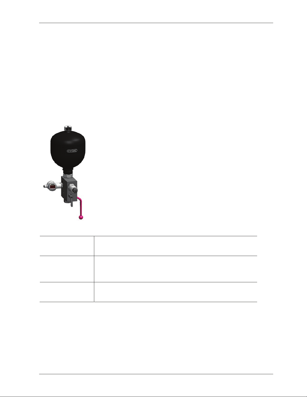
3 Functions of the EDS 3400
3.1 MAIN FUNCTIONS
xPressure sensor with analogue output for pressure monitoring on the fluid side of the
hydro accumulator.
xSupports the control of the accumulator charging function
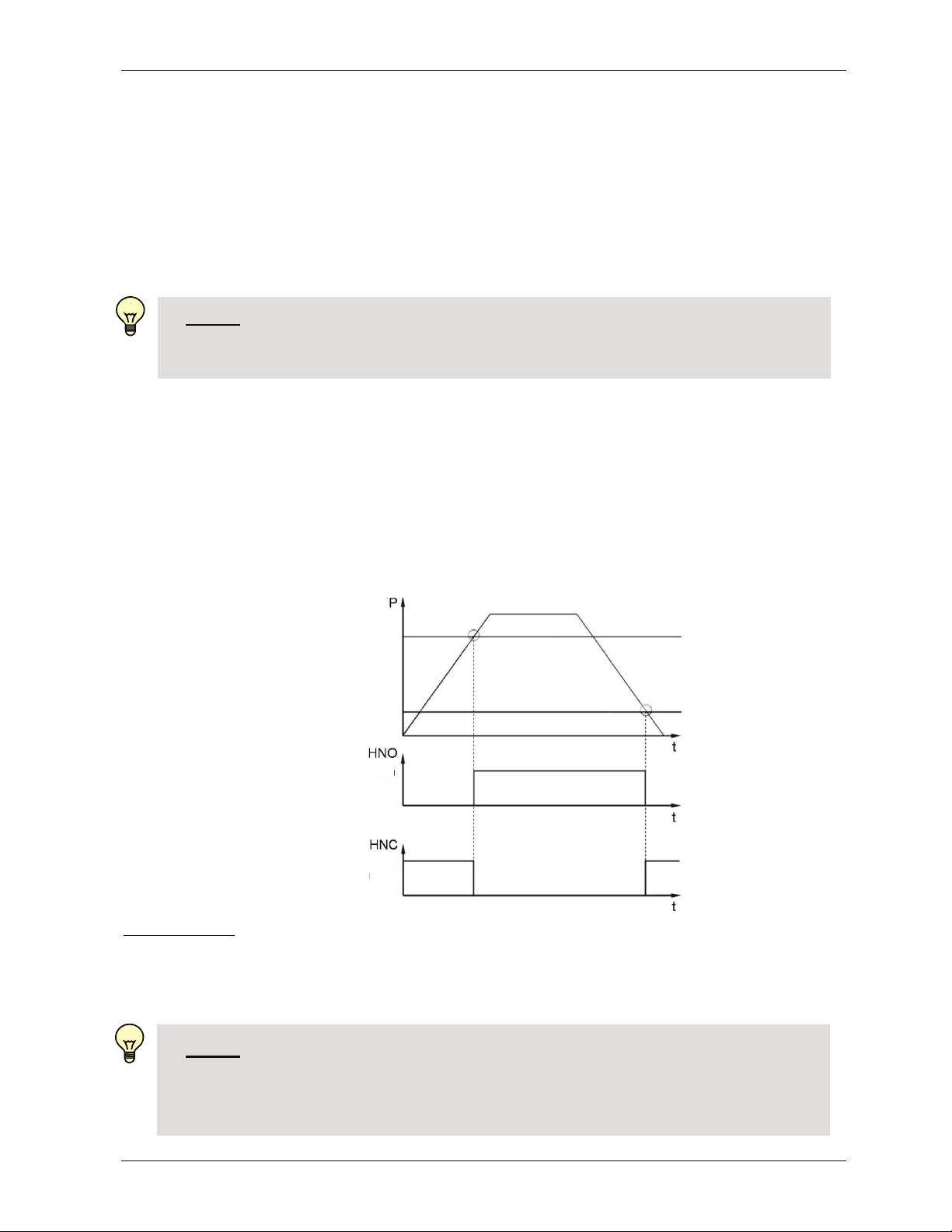
xDetection and signalisation of the accumulator precharge pressure drop (p0)
Æp0-Guard
NOTES:
xIt is essential for the functioning of the p0-Guard that the hydro accumulator has
discharged completely before use.
xThe function of the p0-Guard can be combined with the following HYDAC
accumulator systems:
Bladder accumulators, piston accumulators, diaphragm accumulators, metal
bellows accumulators as well as back-up type hydraulic accumulators and
accumulator stations.
xIf the hydro accumulators are arranged in parallel (e.g. in an accumulator
station with multiple hydro accumulators), the p0-Guard recognises and
signalises the critical accumulator pre-charge pressure (p0) However, an
assignment of the critical hydro accumulator (regarding p0) is not possible.