Hydrajaws 2050 User manual

Operating Instructions
HYD R A J AW S
LIMITED
2050 Model Tester

2050 Model Tester
3
Model 2050 Parts
1. Gauge - Analogue with
QR Hydraulic Coupler
2. Gauge - Digital with
QR Hydraulic Coupler
(optional)
3. Quick release
couplingwhentted
or gauge (1 & 2)
4. Tester body with
50mm/scale indicator
5. Load jaw
1
2
4
11
12
7
8
9
3
6
10
5
2
SAFETY RULES
•Modicationofthetester,ortampering
with it’s parts is not permissible.
•Observetheinformationprintedinthe
operating instructions applicable to
operation care and maintenance.
• The tester and its accessories may
present hazards when used incorrectly
by untrained personnel or not as
directed.
• Use only the genuine Hydrajaws
accessories or ancillary equipment
listed in the operating instructions.
The model 2050 pull-out tester is
a purpose made system for testing
xings, fasteners and anchors. It
consists of a mechanical screw
arrangement acting through a
hydraulic load cell, which measures
the load applied to the xing directly.
The resulting load value is then
indicated on the dial type gauge
or optional digital gauge.
The tester has a built in movement
indicatorscale50mmtoshow“rst
movement”onthexingpriortothe
test load being applied. The tester and
bridge are supplied as an integral part
ofthestandardtesterkit.
Acomprehensiverangeofaccessories
isalsoavailable,furtherincreasingthe
scopeofpossibletestingapplications.
USE OF THE TESTER AS DIRECTED
Thetesterisintendedforusebyskilled
personnel with the appropriate training
andknowledgeoftheapplicablesafety
precautions.
GENERAL DESCRIPTION
It is essential that the
operating instructions
are read before the tester is
operated for the rst time.
Always keep these operating
instructions together with
the tester.
Ensure that the operating
instructions are with the
tester when it is given to
other persons.
6. Turning handle with
integrated nut
7. Grab Handle
8. Displacement sensor
(optional)
9. Level bubble
10. Leg pins
11. Tester bridge
12.Safetyeyehook
CONTENTS
Page
Model 2050 Parts 2
General description 3
Kit contents 4
TechnicalSpecications 5
1. GENERAL TESTING 6
PROCEDURE
2. PULLING ADAPTORS 9
2.1 The bolt test adaptor
Slotted button adaptors
Threaded button adaptors 9
2.2 Threaded Stud Adaptors 10
2.3 The clevis adaptor 11
3. EXAMPLES OF USE 11
3.2 Testing dowels
3.3 Testing anchor bolts
4. CARE OF TESTER 12
4.1 Lubrication
4.2 Oilrellinginstructions 13
4.3 Calibration

4 5
KIT CONTENTS:
1. Model 2050 tester with quick release
hydraulic coupler
2. Turning handle with integral 24mm
Nut-alternativehandleforusein
connedspaces
3. Load spreading bridge with three
telescopic legs and hardened pins
4. Threadedstudadaptors-M16,
M20,M24(+/-30m*)(M10*,M12*)
5. SafetyEyehook
6. SlottedButtonadaptors6.5,8.5,
10.5,12.5
ThreadedButtonadaptorsM10,M12
(M4,M5,M6,M8*)
7. 24mm ratchet spanner
8. 10mmsinglewrench
9. Large ringbolt clevis
adaptorL=120mm*
10.Lockingadaptorsx2:
1.secured inside jaw
2.Attachedtoclevisadaptor*
11. Bolt head M16 adaptor L=95mm
12. Detachable 50kN analogue gauge
13. Detachable 50kN Digital Bluetooth
gauge*
14.USBmemorystick*
15.Sparedigitalgaugebattery*
16. Displacement Sensor plate and
DisplacementSensorlead.*
17. Oil Replenisher Bottle
18.3mmBalldriver
19. Piston key
20. Allen Key
21. Spare screws
22. Carry Case with Filler
23. Operating Instructions
24.CalibrationCerticate
*Optional Accessories:
Forillustrationpurposesthistesterkitfeatures
many optional accessories.
TESTER AND ACCESSORIES
1
22
19
5
16 12
14
15
2
11
8
18
74
4
4
17
9
13
3
21 20
24
23
10
6
10
TECHNICAL SPECIFICATIONS
• Pull-outloadrange 0-50kN/lb/f
• Weight
Tester only 2.5kg
GrossBoxweight 14kg
• Packagedsize 61cmx47cmx18cm
• Effectivestroke 50mm
• Stroke scale 0-50mm
• Load gauge Interchangeable
• Casing Aluminium
• Loading jaw Pivot-able through
360° with Spring
return
• Operating handle Standard size with
integrated 24mm
nutforconned
spaces
Load Gauges
• Rangeavailable:Analogue:0-50kN/lbf
Digital:0-50kN
• Accuracy:Analogueto+/-2.5%fsd
Digitalto+/-0.5%fsd
• Indicationofpull-outload
• Calibrated in kN
• Traceablecalibrationcerticatesupplied
with each gauge
• Protective rubber cover (analogue only)
• Impact resistant glass
• Protectionagainstsuddenloadrelief
(i.e.suddenfailureofxing)
• Digital:peakholdmemory
• WorkingTemperature:
Analogue:-20°Cto+60°C
Digital:-30°Cto+85°C
Bolt head
Threaded Stud
Min
20mm
Max
170mm
Min
20mm
Max
150mm
Min
15mm
Max
137mm
Clevis
with Threaded stud Max 220mm
Adaptor ranges

76
TESTING PROCEDURE
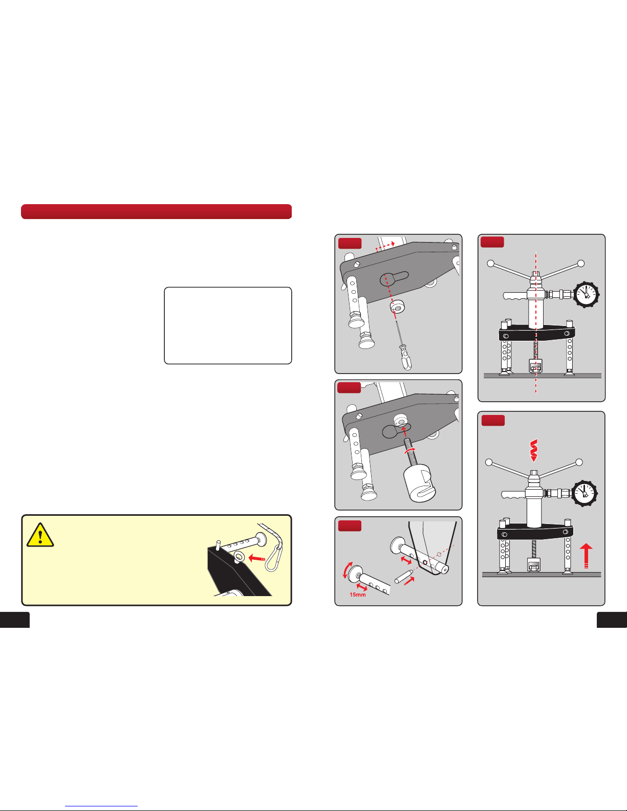
6. Set the red pointer on the gauge to zero
- hold the tester by the grip handle and
proceedtoloadthefastenerbyturning
the operating handle clockwise (g 5).
7. Increase the load until the required
test load is attained. Hold this load and
observeanyfallingbackofthereadings
which would indicate movement and
possiblefailureofthefastener.Record
thesatisfactoryresult.
8.Releasetheloadonthefastenerby
turning the operating handle anti-
clockwise and allowing the test jaw
to return to the original position.
9. Remove the tester and bolt tester
adaptor.
Fig 5
1. GENERAL TESTING PROCEDURE
SETTING UP THE TESTER
1 Fit the appropriate adaptor to the tester.
Exampleshownisabolttesteradaptor.
(Forttingofotheradaptorspleasesee
individual instructions in this manual.)
2. The tester is supplied with a locking
adaptorttedintothetesterbody.
This locking adaptor can be removed
forttingofdifferentadaptorsbyusing
the 3mm Ball Driver. When replacing
backinensureitisfullyengagedinto
thetesterbodybeforetightening
(g 1). Thread the bolt tester adaptor
intothis,untilitisfullyengaged,using
aquarterturnforposition(g 2).
3.Makenaladjustmentssothatthebolt
testeradaptor,testerandxingare
aligned (g 3).
4. Position the tester so that the gauge
can be easily read.
5.Adjustthelengthofthelegssothat
all three are in contact with the base
material and the load spreading bridge
isalignedandlevelbyreferringtothe
bubblelevelsoneachface.
Fine adjustment is available by
unscrewingthefeetbynomore
thanapproximately15mm(g 4).
Fig 3
Fig 4
Fig 1
Fig 2
It is essential when testing on ceilings
(upside down) and/or vertically, that a
safety line is attached from the eyehook
on tester body to a suitable solid xing
point. This will stop the tester falling and prevent
injury to personnel and/or damage to test unit. If
no suitable xing point is available then attach to
safety harness on personnel using the tester.
CAUTION!
Holdthefastenersecurelybythegrip
handleaslongasthefastenerisunder
load.Whentheloadincreases,note
the reading on the displacement scale
onthetester.Indicationoffailureofthe
fastenermaybeobtainedbycomparing
the current reading with the original
reading.

98
2. PULLING ADAPTORS
2.1 THE BOLT TEST ADAPTOR
Using the bolt test adaptor directly
Adjusting the handle position
Using the integrated nut
Using the bolt test adaptor with the slotted button adaptor
ForM16nuts,thebolttesteradaptor(a)
directly engages the nut (b) in the pulling
jaw (g 9).
Mount the Locking adaptor into the tester
(see Section 1 General testing procedure).
Then thread the bolt tester adaptor into the
tester body (g 10).
Fig 9
For testing M12 bolts the slotted button adaptor is used.
Fig 11
Fig 10
b
ca
a
b
Using the bolt test adaptor with
the threaded button adaptor
Fortestingthreadedxingsthethreaded
button adaptor is used.
Mount the locking adaptor into the tester
(see Section 1 General testing procedure).
Then thread the bolt tester adaptor into the
tester body (g 10).
The threaded button adaptor (a) threads
ontothexing(c) and then slots into the
bolt tester adaptor (b) (g 12).Ensurethe
button adaptor has at least 2 complete
threadturnsonthexingandissecure.
Fig 12
b
c
a
Mount the locking adaptor into the tester
(see Section 1 General testing procedure).
Then thread the bolt tester adaptor into the
tester body (g 10).
The slotted button adaptor (a) slots into the
bolt tester adaptor (b) and engages the nut
(c) (g 11).
1. GENERAL TESTING PROCEDURE continued
Fig 6
Fig 7
Fig 8
Inconnedspacestheintegratednutcan
beusedwitha24mmratchetspannerfor
betteraccessinconnedspacesandfor
easier operation (g 6).
Removethehandlesbyunscrewingfrom
the base using the 10mm wrench (g 7).
Ensurewhenre-attachinghandlesthat
they are tight on and secure.
Thetoppartoftheunitcanberotatedif
the handle or gauge becoming obstructed
by the unit legs or other objects.
This is achieved by loosening the three
grub screws (a) on the body using the
allen key provided. Rotate the top until the
handleandgaugeareclearofobstacles
and re-tighten the screws (g 8).
a
a

1110
3. EXAMPLES OF USE
3.2 TESTING DOWELS
3.3 TESTING ANCHOR BOLTS
(MECHANICAL OR CHEMICAL)
Mount the locking adaptor into the tester (see Section 1 General testing procedure).
Thread the bolt test adaptor into the tester (see section 2.1).
(see g 11) UsinganappropriateslottedbuttonadaptorifthescrewissmallerthanM16
(a). Screw a bolt onto the dowel (c) and mount the bolt adaptor (b) to the bolt head.
Oncettedsecurelycommencetesting(seeSection1Generaltestingprocedure).
Mount the threaded stud adaptor to the anchor bolt (see section 2.2).
Removethelockingadaptorifttedintester(seeSection1Generaltestingprocedure).
Mountthethreadedstudadaptorintothetesterensuringitisfullyengaged(g 14).
Start testing procedure (see Section 1 General testing procedure).
For testing ringbolts the Clevis adaptor is
used.
Mount the locking adaptor into the tester
(see Section 1 General testing procedure).
Then thread the clevis adaptor into the
testerbodyuntilitisfullyengaged,usinga
quarterturnforpositioning(g 16).
Removecrosspinfromtheclevisadaptor
andofferthetesterandbridgetoengage
eyeoftheanchorintheclevis.Some
adjustment will be required on the swivel
feet,sothatthistisachieved.Push
clevispinthroughtheclevisandeyebolt,
ensuring that the ball on the pin clicks
intoplace,havingpassedthroughthe
secondfork(g 17).Oncettedsecurely
commence testing (see general testing
procedure on page 6). Fig 17
Fig 16
2.3 THE CLEVIS ADAPTOR
2.2 M16, M20 AND M24 THREADED STUD ADAPTORS
Fig 13
Fig 15
Suitablefortestingsleeveandstud
anchorsof10mm,12mmand16mm.
Aftertheanchorhasbeensetin
accordancewiththemanufacturers
recommendations,asuitablethreaded
rod (a) is screwed into the anchor and
the adaptor (b)thentted.Thelength
ofthethreadedrodtobescrewedinto
the anchor must be at least equal to the
diameteroftheanchor(g 13).
Removethelockingadaptoriftted(see
Section 1 General testing procedure).
Whentheadaptorissecurelyttedto
theanchorthreadposition,placethe
testerovertheadaptor,passingthehead
through the hole in the bridge and engage
itinthepullingjawofthetester(g 14).
Level the load spreading bridge with the
adjustablelegsandswivelfeetbefore
commencingtheapplicationoftheload.
Fig 14
b
a
1 2 3
d
c
Note:TousetheoptionalM30
Threadstudadaptor,rstattachit
toxing(c). Then thread the M20
Adaptor (d) and proceed as above
(g 15).

15m
m3
mm8mm
TOO LOWGOOD
1312
Fig 18
Fig 19
4. CARE OF TESTER
4.1 LUBRICATION
Lubrication of rod
This is required periodically depending
on usage.
Unscrew and remove operating handle.
Take care to avoid moving the washer
andbearingbelow.Greasesurfacesand
threadsbeforere-assembly(g 18).
Oil relling
Connecting and disconnecting Gauges
fromtheTesterbodywilleventuallyuse
up the spare oil capacity and will not allow
thetesterplungertotravelit’sfullstrokeor
give an accurate reading on the Gauge.
Eventuallytheplungerwillstopatapprox.
3mmfromtheedgeandindicatethatoilis
too low (g 19).
(Torelloilsee4.2 oil relling
instructions).
Fig 20
Fig 21
Fig 22
NOTE: A tester with a xed gauge cannot
be lled with oil by the operator.
1. Remove the bridge and all accessories.
2. Secure the tester (e.g. in a vice or other
suitableholdingdeviceifon-site)with
the coupler in the vertical position.
3. Connect the oil bottle via the quick
release coupler.
4. Remove bottle cap (g 20).
5.Turnthehandleanti-clockwiseafew
turns then using the piston key provided
insert this into the groove on the piston.
Ensurethepistonkeyouterslotis
nearer the piston body (g 21).
6.Forceanyairoutofthesystemby
pushingthepistoninfullythenpullon
the piston key and handle until 10mm
awayfromtheinsideoftheslot.This
willdrawoilfromthebottle(g 22).
7.Pushthepistonbackinfully,pullout
again and repeat until all the air bubbles
areexpelledintothebottle,theoilis
replenished,andpistonis10mmfrom
faceoftheBody.
8.Removeoilbottle.
Ensure not to pull the piston out
further than 15mm.
Recommendedoil:
Light Mineral DTE Type
4.3 CALIBRATION
Fromthedateofpurchase,yourtesteriscalibratedforoneyear.Afterthistime,thetester
shouldbereturnedforcalibration.TesterswithBluetoothDigitalwillreceiveareminder
messageontheirdigitaldisplay,onemonthfromdateofrenewal.
10mm
10mm
10mm
4.2 OIL REFILLING INSTRUCTIONS

1514
NOTES

20/21 The Courtyard
Gorsey Lane
Coleshill
Birmingham
B46 1JA
Tel:+44(0)1675430370
Fax:+44(0)1675465950
email:[email protected]
www.hydrajaws.co.uk
HYD R A J AW S
LIMITED
FOR MORE INFORMATION
ON HYDRAJAWS AND A
FULL RANGE OF TESTING
APPLICATIONS PLEASE VISIT
THE WEBSITE AT:
WWW.HYDRAJAWS.CO.UK
Table of contents
Other Hydrajaws Test Equipment manuals
Popular Test Equipment manuals by other brands

Uson
Uson Qualipak-770 manual

MSA
MSA Multitest plus Console operating manual

Agilent Technologies
Agilent Technologies InfiniiVision 2000 X-Series Programmer's guide

Reed Instruments
Reed Instruments R5820 instruction manual

Hantek
Hantek DPO6000 Series product manual

Rsrteng
Rsrteng IPC-7600 Plus Series user manual