Hydrajaws M35+ User manual

1
Dual Load Capacity
M35
+
Modular Pull Tester
MAKE SURE IT’S SECURE
www.hydrajaws.co.uk
P
I
O
N
E
E
R
I
N
G
S
A
F
E
T
Y
OVER
35
YEARS
T
R
U
S
T
E
D
W
O
R
L
D
W
I
D
E
www.hydrajaws.co.uk
USER
MANUAL

2
Rechargeable battery MUST be charged before rst use. Refer to the
‘Hydrajaws Rechargeable Digital Gauge’ section for more details.
SPECIFICATIONS
Pull-out load range: 0-65kN/14,613lbf
Max torque: @35kN = 9.8Nm/7.2ft-lbs
@65kN = 18.8Nm/13.9ft-lbs
Weight: Tester only: 3.7kg/8.16lbs
Standard kit with Rucksack: 8.7kg/17.6lbs
Hydraulic Oil: Light Mineral DTE Type VISCOSITY 32
Certication: CE; UKCA
Bridge Footprint and Tester dimensions
The standard bridge can test most applications up to 35kN (7,868lbf).
Two optional bridges are available for loads up to 65kN (14,613lbf) and allows for greater span
and spacing requirements.
Gauge IP Rating: IP54 *
Operating temp. range: -10° C to +50° C (14° F to 122° F)
Configurable units: kN, lbf
Operating voltage: 9V
Battery type: Rechargeable **
MIN
Height
MAX Height
110mm Span (4.3")
210mm Span (8.3")
310mm Span (12.2")
STANDARD BRIDGEMEDIUM BRIDGELARGE BRIDGE
MIN
Height
MIN
Height
178 mm (7") 334 mm (13 .1")
178 mm (7") 410 mm (16.1" )
120 mm (4.75") 363 mm (14.3")
334 mm (13 .1")
410 mm (16.1")
363 mm (14.3")
120 mm (4.75”)178 mm (7”)
178 mm (7”)
312 mm (12.3")
425 mm (13.7")MAX Height
312 mm (12.3")
425 mm (13.7")MAX Height
312 mm (12.3")
425 mm (13.7")
*BS EN 60529: 1992 + A2: 2013: Degrees
of Protection Provided by Enclosures
** Battery model:
EBL TB9500, PP3

3
The tester is intended for use by skilled personnel with the appropriate training
and knowledge of the applicable safety precautions.
The Hydrajaws M35+ Dual Load Capacity Modular Pull Tester is designed for
establishing linear loading of mechanical and resin anchors, eye type anchors,
threaded bar and structural bolts and fixings to a load of 35kN (7,868lbf) with
the standard bridge or maximum 65kN (14,613lbf) with medium or large bridge.
SAFETY RULES
Modication of the tester, or tampering with
its parts is not permissible.
Observe the information printed in the
operating instructions applicable to operation
care and maintenance.
The tester and its accessories may present
hazards when used incorrectly by untrained
personnel or not as directed.
Use only the genuine Hydrajaws accessories
or ancillary equipment listed in the operating
instructions.
It is essential that the
operating instructions
are read before the tester is operated
for the first time.
Always keep these operating
instructions together with the tester.
Ensure that the operating instructions
are with the tester when it is given to
other persons.
M35+ General Description
CONTENTS
USE OF THE TESTER AS DIRECTED
Technical Specications, Dimensions and Footprints 2
General description 3
1. Overview of the Standard M35+ Tester Kit 4
2. General Testing Procedure – Set up 6
3. General Testing Procedure – Operating the tester 8
4. Adaptors 10
5. Modular bridges 12
6. Hydrajaws Rechargeable Digital Gauge 16
i. Hydrajaws Verify 20
ii. Set up a Hydrajaws Verify account 21
iii. Download the Verify App and Sign in 21
iv. Connecting the gauge to the Verify App 21
Notes 22
Appendix: Rechargeable Battery Information 23

4
The M35+ is a compact, lightweight, dual
load capacity modular digital pull tester
designed to test eye bolts and anchors.
1. OVERVIEW: M35+ DUAL LOAD MODULAR PULL TESTER
Featuring Easi-Eort® technology, the M35+ can increase
testing frequency whilst reducing operator eort.
1
4
11
7
13
6
5
12
8
14
18
15
Built-in ‘Easi-Eort®’ technology enables
the load to be applied in a eortless and
consistent action at high loads.
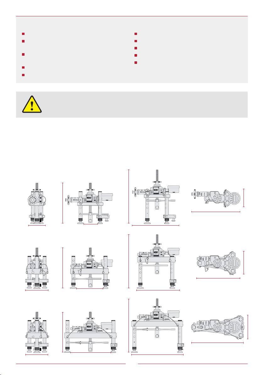
The standard unit has a load capacity of
35kN (7,868lbf), and by coupling to one
of the larger bridges the load capacity is
increased to a maximum of 65kN (14,613lbf)
with the benet of an increased span.
The drop rod incorporates a primary
clevis adaptor (11) which accepts a bolt
test adaptor (13) for use with slotted
and threaded button adaptors which are
included with the kit. It also accepts the
mini-clevis adaptor (12).
The three height adjustable legs (7) oer
four height positions 30mm apart. They are
held in place with steel ball pins, and the
back two legs kept parallel by a brace (10).
The brace will extend to allow the legs to t
optional larger bridges.
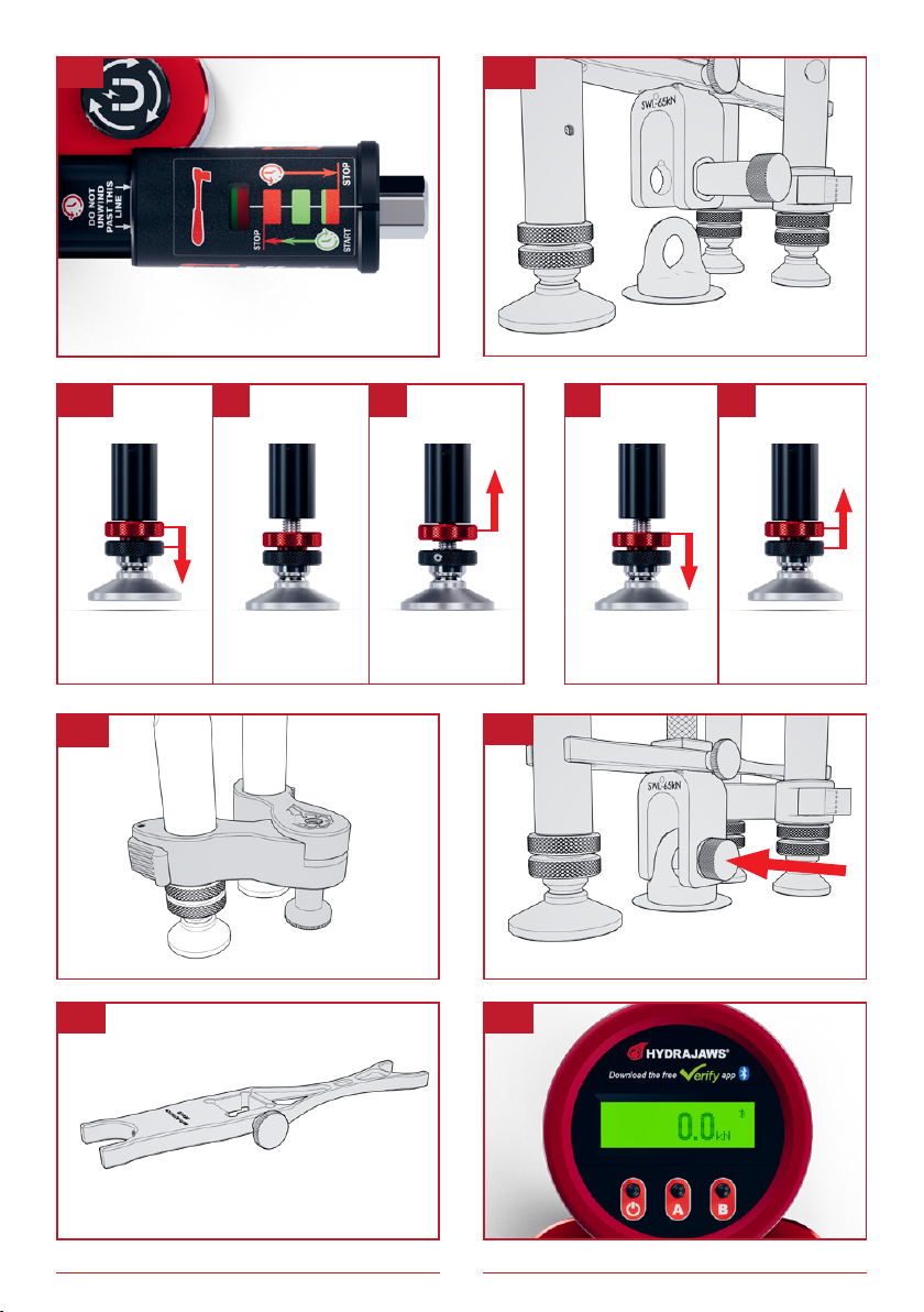
The swivel feet oer 12mm of usable ne
adjustment.
The drop rod handwheel (5) is used to
secure and apply a pre-load to the xing.
The ‘Anti-rotation device’ (8) prevents the
adaptor turning during pre-load.
Load is applied with either the operating
handwheel (6) or ratchet driver (16).
The load is displayed by the rechargeable
digital gauge (3), and can be recorded by the
Hydrajaws Verify App.
Tester lanyard and ratchet tether are included
for work at height.

5
M35+ Tester Standard Kit Contents
3
9
1. M35+ Load Cell
2. 35kN (7,868lbf) Standard
Bridge
3. 0-65kN (14,613lbf) Digital
Gauge
4. ‘Easi-Eort®’ Indicator
5. Drop rod handwheel
6. Operating handwheel
7. 3 x height adjustable legs with
fully adjustable swivel feet
8. Anti-rotation device
9. 3 x Removable leg caps
10. Leg brace
11. Drop rod with Clevis adaptor
12. Mini Clevis adaptor
13. Bolt test adaptor
14. Slotted adaptors:
(Available in Metric or Imperial,
subject to kit)
15. Threaded adaptors:
(Available in Metric or Imperial,
subject to kit)
16. Ratchet Driver
17. Ratchet Tether
18. 24mm Single Spanner
19. Rucksack with Foam Filler
20. Operating Instructions
21. Calibration Certicate
22. Tester Lanyard (Not shown)
23. 3mm Ball Driver (Not shown)
24. Gauge Cover (Not shown)
25. USB Charging Cable (Not shown)
Optional items: (Not shown)
Medium Bridge; Large Bridge;
M20 to M24 Hex Adaptor;
M20 to M30 Hex Adaptor;
Leg Extensions
10
16
17
20 21
19
2

6
2.1 The M35+ is supplied with the standard bridge. If
appropriate, secure the M35+ tester to the medium
or large bridge (See Section 5 – Modular Bridges)
2.2 Ensure that the position of the Operating Nut is at the
start position. The window shows
(g 2.2).
2.3 Attach the drop rod with an appropriate adaptor if
required (See Section 4 – Adaptors).
2.4 Position the tester and bridge over the xing.
2.5 Adjust the length of the adjustable legs so that all
three are in contact with the base material and the
tester is aligned and level referring to the bubble
levels on the bridge.
2.6 If required adjust the swivel feet to aid levelling.
Start by bringing both adjustment screw wheels
(2.6a) down together to the required position (2.6b).
Then screw the top wheel back up to lock into
place (2.6c).
To undo, screw the top wheel down to meet the
bottom wheel (2.6d) then move them both back up
together (2.6e).
2.7 Always ensure the leg brace is tted to give the
tester stability when under load.
2.8 Connect the adaptor to the xing.
2.9 The Anti-rotational device will prevent the adaptor
turning around the xing during pre-loading.
2.10 Switch the digital gauge on (see Rechargeable
Digital Gauge instructions – Section 6). If using the
Hydrajaws VERIFY app, connect it to the gauge.
2. GENERAL TESTING PROCEDURE — SET UP
PREPARE FOR TESTING
It is recommended when testing on ceilings
(inverted) and/or vertically, that a safety line
is attached around the tester body (either
through the loop hole or through the middle) and
attached to a suitable solid xing point. This will stop
the tester falling and prevent injury to personnel and/or
damage to test unit.

7
2.2
2.7
2.4
2.6a
2.9 2 .10
2.8
b ec d

8
3. GENERAL TESTING PROCEDURE — OPERATING THE TESTER
3.1 Apply a pre-load using the drop rod handwheel until a load
of up to 0.4kN (90lbf) is displayed on the gauge.
3.2 Commence applying the load to the xing by using either
the operating handwheel (up to 10kN (2,248lbf)) or the
ratchet driver in a clockwise direction and observe the
reading on the gauge until the required test load is reached.
3.3 Due to the accuracy of the digital gauge, relaxation will
occur from the required test load. An allowance of +5%
over the required load (ie. 6kN +5%= 6.3kN (1,348lbf +5%=
1,416lbf)) is accepted.
3.4 If the reading continues to relax, further investigation of the
xing would be required.
3.5 When testing is complete turn the handwheel or ratchet
driver anti-clockwise to the stop position .
3.6 If using Verify app it is important to release the pre-load
from the drop rod handwheel to enable a zero reading.
3.7 Extra Pre-load (Fixings with more displacement)
Firstly, apply higher load by using the 24mm single spanner
on the drop-rod handwheel to the main piston (up to
approximately 15kN (3,372lbf)). Then continue testing using
the ratchet driver.
By using this method, more working stroke is available by
operating the ratchet driver on the slave piston.
TESTING
When applying load, stop
when the window is fully red.
When releasing load, stop
when the window is red with a
green stripe. Do not wind further
past the white line as stated on
the inner sleeve.
DO NOT
CONTINUE TO
WIND AGAINST
THE STOPS,
OTHERWISE
DAMAGE MAY
OCCUR

9
3.1
3.2
3.6
0.0 k bN
3.7
0.4 k b
3.5

10
For testing ring bolts the Clevis adaptor is
used.
4. ADAPTORS
CLEVIS
MINI-CLEVIS
For smaller diameter fall arrest eye bolts, the
mini clevis is required.
Ax to the main clevis by attaching it through
the large crosspin.
Turn and release the crosspin from the clevis
adaptor.
Press to engage the crosspin through the eye
of the anchor and turn it 90° to secure.
THE HEXAGON ADAPTOR
Suitable for testing sleeve and stud anchors.
To use the optional M24 and M30 hexagon
adaptors, rst attach the adaptor onto the rod
to be tested (g 4.8a).
Then screw on a M20 threaded adaptor on
to the thread of the hexagon (4.8b), and then
oer this in the jaws of the bolt adaptor (4.9).
4.1
4.2
4.3
4.7
The clevis can be rotated in 90° increments to
better engage an anchor (g 4.2).

11
BO LT ADAPTOR
Using the bolt test adaptor with the
slotted button adaptor
Using the bolt test adaptor with the
threaded button adaptor
For testing xings where a connection is made
underneath the head of the xing or anchor
the slotted button adaptor is used.
The slotted button adaptor (4.5a) slots into
the bolt tester adaptor with the aid of magnets
(4.5b) and engages the xing (4.5c).
For testing threaded xings the threaded
button adaptor is used.
The threaded button adaptor (g 4.6a) threads
on to the xing (4.5b) and then slots into the
bolt tester adaptor (4.5c).
Ensure the button adaptor has been threaded
enough that the top of the rod is ush with the
top of the xing thread.
The bolt test adaptor is utilised by attaching it
to the clevis through the crosspin.
The bolt test adaptor is used in conjunction
with the supplied slotted button and threaded
button adaptors, which are easily located into
the magnetised adaptor. Larger headed bolts
can also be directly located into the adaptor.
c
4.4
4.5
4.6
4.8 4.9
b
a
a
bc
b
a

12
The Standard bridge allows for testing up 35kN
( 7,8 6 8l bf ). Its footprint allows for a span of
110mm.
SELECTING THE CORRECT BRIDGE
The modular nature of the M35+ tester allows the standard unit to be easily
extended by utilising the same legs and pins in all three bridge congurations.
5. MODULAR BRIDGES
The optional Medium bridge can test up to 65kN
(14,613lbf), with a span of 210mm.
The optional Large bridge can span 310mm and
can test loads of up to 65kN (14,613lbf).

13
2. Unscrew and release the caps located
at the top of the legs. These caps are
magnetic and can be conveniently
attached to the drop rod handwheel for
safekeeping.
To use a larger bridge:
3. Remove single leg pin and slide out leg.
4. Then remove the two remaining leg pins
and slide out the legs together.
1. Begin by standing the unit on a at
surface. Remove the drop rod handwheel
from the drop rod.
5. Now slide out the drop rod from the load
cell and bridge unit.

14
5. MODULAR BRIDGES — Continued
6. Slot into your chosen bridge:
7. Take the two back legs and loosen the
thumbscrew on the leg brace. Reposition
the two pieces onto the appropriate lug.
Tighten the thumbscrew. Then slide the
legs into the larger bridge.
LARGE BRIDGE
Position the standard bridge into the
slot of the Large bridge and secure it in
place using the three cap screws that are
shipped with the large bridge.
MEDIUM BRIDGE
Position the standard bridge into the slot
of the Medium bridge and secure it in
place using the bridge retaining pin.
8. Unlock the two tabs to release the grip on
the legs, rotate the legs until their holes are
aligned and locked by their retaining pins,
and then lock the leg brace tabs.

15
When using the leg brace on the standard
bridge ensure that the thumbscrew on the leg
brace faces out and down from the centre of
the tester, so that it is not in the way of the
anti-rotation device.
9. Loosen the thumbscrew of the Anti-
Rotation Device.
10. Insert the drop rod up through the load cell.
11. Insert the front leg into the larger bridge
and x it to your desired height with its
retaining pin.
12. Replace the leg caps on all legs.
MEDIUM BRIDGE
Rotate the device 180° on the drop rod and
re-tighten the thumbscrew. This will brace
on to the single front leg when the leg is
inserted into the bridge.
LEG EXTENSIONS
These can be tted by removing the leg
caps from the standard legs and screwing
the leg extensions into place. The leg caps
can then be screwed on to the top of the
extension legs.
LARGE BRIDGE
Connect the Anti-rotation device
extension as shown. Rotate the device
180° so that it will brace on to the single
front leg and re-tighten thumbscrew.
180°

16
CAUTION:
The gauge should not be loaded above its maximum
load capacity as permanent damage will occur.
pb
HYDRAJAWS
RECHARGEABLE
DIGITAL GAUGE
Bluetooth
Indicator
Peak Hold
Indicator
Power
Button
Battery Level
Indicator
kN
/
lbf
Indicator
USB
Charge
port
/
cover
6. Hydrajaws Rechargeable Digital Gauge
The Hydrajaws rechargeable digital gauge provides accurate and clear results.
CONTENTS 6.1. Operating the Digital Gauge ........................... 17
6.2. Activating the back light.................................. 17
6.3. To switch from kN to lbf .................................. 18
6.4. Zeroing the gauge ........................................... 18
6.5. Activating Bluetooth........................................ 18
6.6. Battery indicator ............................................. 18
6.7. Charging the battery ....................................... 19
6.8. Removing and retting the battery ................. 19
i. Hydrajaws Verify ............................................. 20
ii. Set up a Hydrajaws Verify account................. 21
iii. Download the Verify App and Sign in ............. 21
iv. Connecting the gauge to the Verify app ......... 21
A. Rechargeable Battery Information...................22

17
0.0k pb
Press button
to switch gauge on to ‘Normal rise and fall mode’.
This will give a load reading, rising as the operating handle on the tester is turned
clockwise. By turning the handle anti-clockwise the load will decrease and show the
reading decreasing.
Press
to switch o gauge when nished.
TO OPERATE GAUGE IN ‘NORMAL RISE AND FALL’ MODE
TO OPERATE GAUGE IN ‘PEAK HOLD’ MODE
1. Press button to switch gauge on.
2. Press to activate ‘Peak Hold’ mode.
This will be indicated by an arrow on screen.
Gauge is now in peak hold mode and will display the
maximum load achieved and retain this even when the load has decreased.
To turn ‘Peak Hold’ mode on and o use the button.
6.1 OPERATING THE DIGITAL GAUGE
0.0k pb
Note: When rst turned on, a bluetooth symbol will ash in the
right corner of the screen. This is used when connecting to the
Hydrajaws Verify App and will stop ashing after 60 seconds.
Press and HOLD the button to switch the back light on and o.
To preserve battery life it is recommended the backlight is
used only when needed and is switched o when the gauge
is not in use.
6.2 ACTIVATING THE BACK LIGHT
0.0k pb
0.0k pb

18
Press button to switch between:
kN (Kilo-Newton)
and
lbf (Pound-Force).
6.3 TO SWITCH FROM kN TO lbf
)>)l PB
)>)k PB
If the gauge is reading a small amount (0.3 for example)
when no load is applied – use the following instructions
to re-set the display to zero.
Press and HOLD the
button to zero the gauge.
6.6 BATTERY INDICATOR
0.0k pb
0.3k pb
6.4 ZEROING THE GAUGE
CAUTION: DO NOT ZERO THE GAUGE
WHEN IT IS UNDER LOAD
Press the
button to turn on the gauge. The bluetooth will start – indicated by a ashing
bluetooth symbol. This will remain open for connection for 60 seconds.
When connected to a mobile device, the Bluetooth symbol will stop ashing and remain on.
See separate Hydrajaws Verify app instructions on how to connect a gauge to the app.
6.5 ACTIVATING BLUETOOTH
(To connect to Hydrajaws Verify App)
Indicates in the charge of the battery as a percentage. 0.0k pb

19
To prevent damage to the contacts,
follow the numbered steps as shown
Remove battery
TO AVOID
DAMAGE
INSERT
BATTERY
AS SHOWN
1
32
TO AVOID
DAMAGE
INSERT
BATTERY
AS SHOWN
Fit battery
12
3
To charge the battery, remove the port
cover at the side of the gauge and insert
the lead into the recharging port.
If the rechargeable battery is discharged,
and charging is not available – then a
standard alkaline 6LR 61
/ PP3 9V battery
may temporarily be used.
Remove the cover on the back of the
gauge using the thumbscrew.
Replace and t as shown here.
Rechargeable Battery information:
See notes on page 22
6.7 CHARGING THE BATTERY
6.8 REMOVING AND REFITTING THE BATTERY (if recharging is not possible)
A discharged battery takes approximately
2 hours to fully charge with a 5V 1000 mA
rated USB charger.
The LED is
Red when
the battery is
charging.
And is Blue
when the
battery is fully
charged.
Always use the USB cable to charge the
battery – Do not use a separate lithium
battery charging unit.

20
i. HYDRAJAWS VERIFY
Hydrajaws Verify is our digital reporting system which allows on site
pull tests to be automatically recorded and compiled into a digital report
using our free Hydrajaws Verify Pro App on a mobile phone or tablet.
Report from on site
Job details can be set up before going on-site
and used again and again to save valuable
work time. When on-site a digital report is
generated showing all the test data including
a pass or fail result, a visual results graph,
xing details, site location co-ordinates, date
and time. In addition, any notes and photos
taken can be included within the report too.
The report is easily emailed directly to your
customer or securely stored for future retrieval.
Prove your test results
The app captures and records the digital
report and saves it securely to the cloud.
The real time data is collected onto an
unchangeable and unhackable platform.
This system mitigates the risk of someone
tampering with the results by providing a fully
auditable and transparent data provenance
trail that is admissible in a court of law.
Digitally record all test results and store them safely in the cloud;
review data and generate reports
PRO or TEAMS: Which one is right for me?
The Verify PRO app is fully featured and free to use with
no subscription required. Ideal for single users.
Upgrading to TEAMS allows an administrator to manage
your testing by creating and editing clients, sites and tasks
centrally, and assign remotely to your team of eld testers.
Annual subscription fee applies. Up to 3 users £300 then
£125 per additional user up to 10 users. Above 10 users POA.
erify
PRO
erify
erify
Table of contents
Other Hydrajaws Test Equipment manuals
Popular Test Equipment manuals by other brands

Apera Instruments
Apera Instruments LabSen 553 user manual

Rigol
Rigol SA5000 Series Programming guide

Oxford PRECISION
Oxford PRECISION OXD-516-0225E Operator's manual

Tektronix
Tektronix TBS1000B Series user manual

Andatech
Andatech SOBERMATE S3 user manual

Teledyne Lecroy
Teledyne Lecroy PXP500 PCI Express user manual