3
SAFETY RULES
•Modicationofthetester,ortampering
with its parts is not permissible.
• Observe the information printed in the
operating instructions applicable to
operation care and maintenance.
• The tester and its accessories may
present hazards when used incorrectly
by untrained personnel or not as
directed.
• Use only the genuine Hydrajaws
accessories or ancillary equipment
listed in the operating instructions.
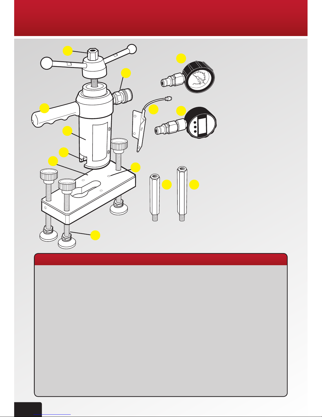
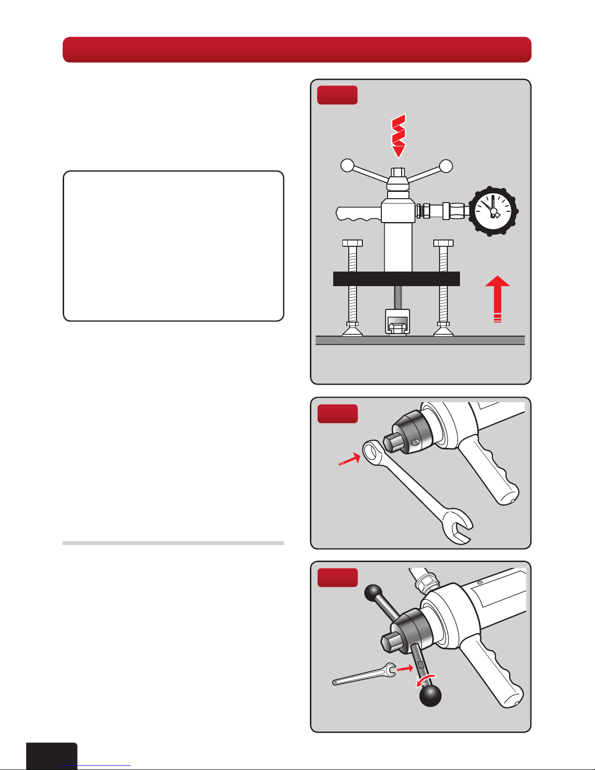
The model 2000 pull-out tester is
a purpose made system for testing
xings, fasteners and anchors. It
consists of a mechanical screw
arrangement acting through a
hydraulic load cell, which measures
the load applied to the xing directly.
The resulting load value is then
indicated on the dial type analogue
gauge or optional digital gauge.
The tester has a built in movement
indicatorscale50mmtoshow“rst
movement”onthexingpriortothe
test load being applied. The tester and
bridge are supplied as an integral part
of all the 2000 tester kit ranges.
A comprehensive range of accessories
is also available, further increasing the
scope of possible testing applications.
USE OF THE TESTER AS DIRECTED
The tester is intended for use by skilled
personnel with the appropriate training
and knowledge of the applicable safety
precautions.
GENERAL DESCRIPTION
It is essential that the
operating instructions
are read before the tester is
operated for the rst time.
Always keep these operating
instructions together with
the tester.
Ensure that the operating
instructions are with the
tester when it is given to
other persons.
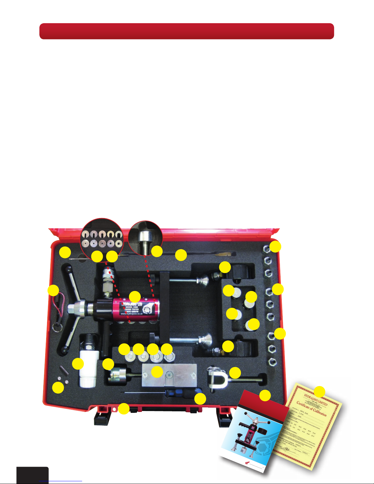
CONTENTS
Page
Model 2000 Parts 2
TechnicalSpecications 2
General description 3
Kit contents 4
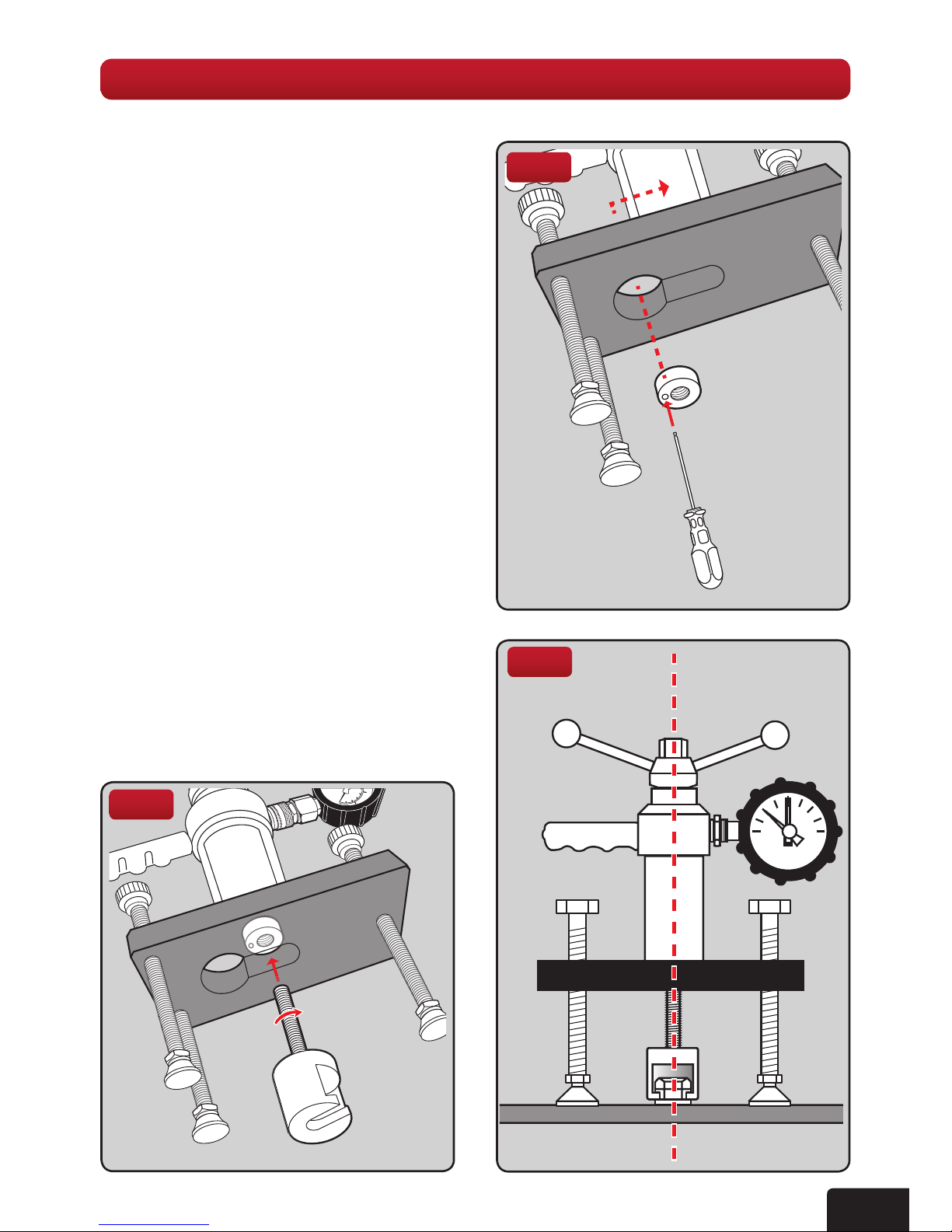
1. GENERAL TESTING
PROCEDURE 5
2. PULLING ADAPTORS 8
2.1 The bolt test adaptor
Slotted button adaptors
Threaded button adaptors
2.2 Threaded stud adaptors 9
2.3 The insulation adaptor
2.4 Threaded rod adaptors 10
2.5 The clevis adaptor
3. SCAFFOLD TESTER KIT 11
4. SAFETY HARNESS EYEBOLT
TESTER KIT 14
5. WALL TIE TESTER KIT 16
6. MATERIAL BOND TESTER KIT 18
7. OPTIONAL LOAD
SPREADING BRIDGES 21
8. FITTING HEX EXTENSION LEGS 21
9. CARE OF TESTER
9.1 Lubrication 22
9.2 Oilrellinginstructions 23
9.3 Calibration