2
13
45
6
7
2a
2
1345
6
7
2a
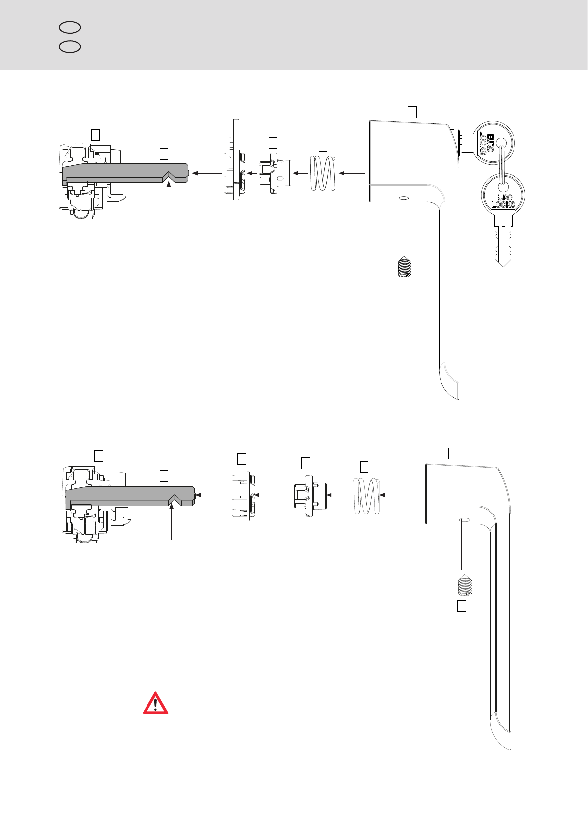
GB Mounting sequence
1. Insert the gear into the profile (pos.1)
2. Slide the square pin (pos.2) at an angle into the gear taking care that the retaining nose
(pos.2a) fits correctly
3. Press the rosette (pos.3) into the profile opening
4. Insert the fixing sleeve (pos.4) into the rosette (pos.3)
5. Slide the coil spring (pos.5) onto the fixing sleeve (pos.4)
6. Push the handle (pos.6) over the previously assembled parts (pos. 2,3,4 and 5) until it
rests against the rosette and hold it there
7. Screw in the threaded pin (pos.7) making sure that the pointed end sits tightly in the notch
of the square pin.
8. Fix the gear (pos.1) into the profile
Representations in closed position
Sous réserve de modications. Subject to alterations. 57401 01.2022 5
Ordre de montage
F
1. Déposer la crémone dans le profilé (pos. 1).
2. Introduire le carré (pos. 2) en biais dans la crémone et veiller à ce que l'accroche du nez
(pos. 2a) soit correcte.
3. Presser la rosette (pos. 3) dans l'échancrure du profilé.
4. Insérer la douille de fixation (pos. 4) dans la rosette (pos. 3).
5. Enfiler le ressort hélicoïdal (pos. 5) sur la douille de fixation (pos. 4).
6. Pousser la poignée (pos. 6) sur les pièces pré-montées (pos. 2, 3, 4 + 5) jusqu'au
contact de la poignée avec la rosette et la maintenir en position.
7. Visser la vis pointeau (pos. 7) et veiller à la bonne assise de la pointe dans l'encoche
du carré.
8. Fixer la crémone (pos. 1) dans le profilé.
Représentations en position fermée