4
Motor:
Each motor is provided with heat
sensor thermostats attached
directly to the motor windings.
The thermostats open if the motor
windings see excessive heat and,
in turn, open the motor contactor
in the control panel, breaking the
power to the pump. When the
motor is stopped due to an
overheat condition, it will not
start until the motor has cooled
and the heat sensor reset button is
manually pushed on the front of
the Hydromatic control panel.
This circuitry is provided in the
Hydromatic control panel
designs.
The SPX50 and SPX50H pumps
are equipped with internal
thermostats. The SPX50 and
SPX50H models are designed to
meet Class B heat rise of
266°F (130°C).
NOTE: Failure to use proper
circuitry and to connect the
motor overheat protection in
the control panel would negate
all warranties and CSA listings.
Motor Seal Failure Warning:
The seal chamber is oil filled and
provided with moisture sensing
probes to detect water leakage
through the lower shaft seal. The
probes can also detect moisture
present in the upper motor
housing.
The presence of water energizes a
red seal leak warning light at the
control panel. This is a warning
light only, and does not stop the
motor. It indicates a leak has
occurred and the pump must be
repaired. Normally, this indicates
the outboard seal has leaked.
Allowing the unit to operate too
long after the warning could
cause upper seal leakage along
with motor failure.
The resistance across the moisture
sensing (seal failure) probes
should be checked after a seal
leak warning light has been
activated. This can be done by
disconnecting the red and orange
control wires from the control
panel and measuring the
resistance with an ohmmeter
between the wires. For an
explosion-proof pump the reading
should be above 30,000 ohms. If
the measured values are below
those indicated above, the pump
may have a lower seal failure and
require service.
On the Hydromatic explosion-
proof control panels the seal leak
test switch tests the seal leak
circuit continuity. When pushed,
the seal leak test bulb should
light. If the test bulb does not
light, it means either the wiring
circuitry to the seal leak probes
has been broken or the bulb has
burned out.
NOTE: Hydromatic built
control panels supply the
correct circuitry for moisture
and heat sensor connections.
Failure to install the correct
circuitry with the proper
connection would negate
warranty and CSA listing.
See page 9.
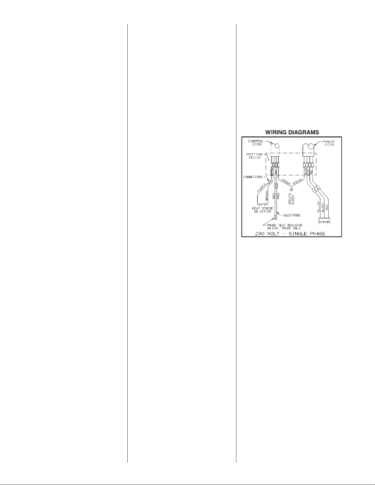
Motor Power Cord, Control
Cord and Cord Cap Assembly:
Each motor power cord has 4
conductors: white, black, red and
green. For a single phase motor
the black is connected to the
common lead, the white is
connected to the main lead, while
the red is connected to the start
circuitry, and the green is
attached to a good ground. The
rotation of a single phase pump is
set properly at the factory.
NOTE: Rotation should be
clockwise when observed from
the top of the pump. This can
be checked by noting which
direction the pump torques
upon initial starting. A properly
rotating pump will torque
counterclockwise upon start.
The control cable has 5
conductors: black, white, red,
orange and green. White and
black connect to the heat
sensor terminals in the control
panels; red and orange
connect to the seal failure
terminals in the control panel;
and the green connects to the
ground in the control panel.
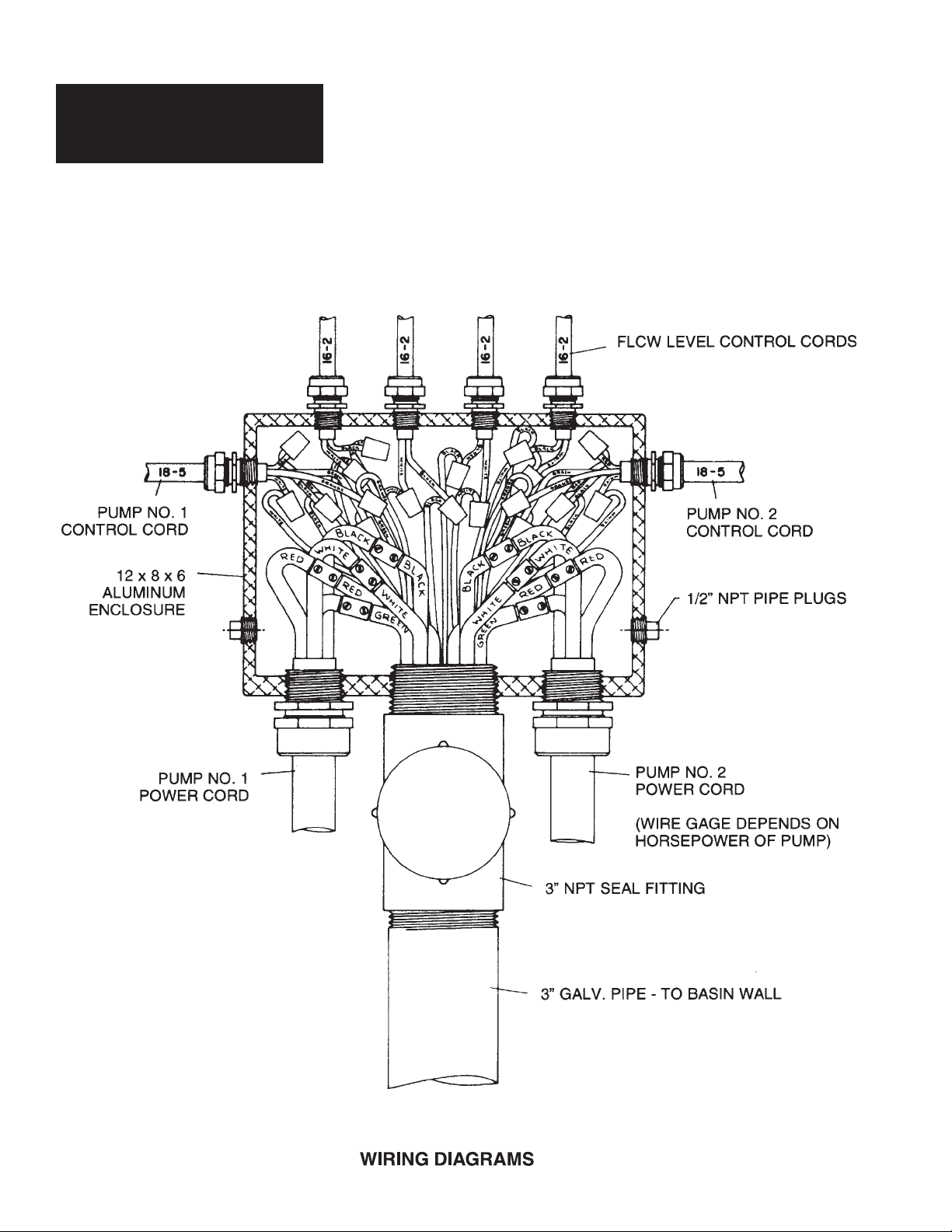
The cord cap is epoxy
potted. This allows the cord cap,
with cords, to be removed from
the motor. With this arrangement,
the cords can be permanently
installed in a sealed fitting in
the sump. This should be
an approved explosion-proof
junction box for hazardous
locations. The control and power
cables cannot be spliced!