Hypontech HMS-600W User manual

HMS-600W / 800W
Micro Inverter
USER MANUAL
V1.00

CATALOGUE
1. Important Safety Instructions ........................................................................... 4
1.1 Radio interference statement .......................................................................................... 4
1.2 Safety requirements ......................................................................................................... 5
2. Micro Inverter System Introduction ................................................................ 7
3. Working Mode .................................................................................................... 8
3.1 Work Mode ....................................................................................................................... 8
4. UNPACKING ......................................................................................................... 9
3.1 Product Overview ............................................................................................................. 9
5. INSTALLING ....................................................................................................... 10
5.1 Installation Requirement ................................................................................................ 10
5.2 Mounting ......................................................................................................................... 11
6. START UP AND OPERATION ........................................................................... 14
6.1 Safety Check Before Start Up ......................................................................................... 14
6.2 Inverter LED Indicators ................................................................................................... 14
7. DISCONNECTING FROM VOLTAGE SOURCES ............................................. 15
8. TECHNICAL PARAMETERS ............................................................................... 16
9. TROUBLE SHOOTING ....................................................................................... 18
10. ACCESSORIES SUMMARY ............................................................................ 21
HMS-600W / 800W USER MANUAL 4
1. Important Safety Instructions
1. The Micro Inverter is designed and tested according to international safety
requirements. However, certain safety precautions must be taken during installation
and operation. Installation personnel must read and follow all instructions,
precautions, and warnings in this installation manual.
2. Specifications subject to change without notice - please ensure you are using the
most recent update found at https://www.hypon.com.
1.1 Radio interference statement
CE EMC Compliance: The equipment can comply with CE EMC, which are designed to
protect against harmful interference in a residential installation. The equipment could
radiate radio frequency energy and this might cause harmful interference to radio
communications if not following the instructions when installing and using the equipment.
But there is no guarantee that interference will not occur in a particular installation. If this
equipment causes harmful interference to radio or television reception, the following
measures might resolve the issues:
1.Relocate the receiving antenna and keep it well away from the equipment.
DANGER, WARNING AND
CAUTION CE MARKS
HIGH VOLTAGE
AVOID CONTACT
Etiquette Onduleur.
HIGH TEMPERATURE
AVOID CONTACT
USER MANUAL IN PACK
DO NOT DISPOSE WITH
HOUSEHOLD WASTE

5 HMS-600W / 800W USER MANUAL
2. Place the shield between the Micro Inverter and the receiving antenna, such as
metal.
3.Consult the dealer or an experienced radio/TV technical for help.
Changes or modifications not expressly approved by the party responsible for
compliance may void the user’s authority to operate the equipment.
1.2 Safety requirements
Only qualified personnel can install and replace inverters
Before installing or using the Micro Inverter, please read all instructions and
cautionary markings in the technical documents and on the Micro Inverter system and the
solar-array
Perform all electrical installations in accordance with local electrical codes
Do NOT disconnect the PV module from the Micro Inverter without disconnecting
the AC power.
Be aware that the body of the Micro Inverter is the heat sink and can reach a
temperature of 80°C. To reduce risk of burns, do not touch the body of the Micro
Inverter.
Do NOT attempt to repair the Micro Inverter. If it fails, contact Customer Support
(+86 400 6339 990) to start the replacement process. Damaging or opening the Micro
Inverter will void the warranty.
Do NOT expose the connection to directed, pressurized liquid (water jets, etc.).
Do NOT expose the connection to continuous immersion.
Do NOT expose the AC connector to continuous tension (e.g., tension due to pulling
or bending the cable near the connection).
Do NOT allow contamination or debris in the connectors.
Use only the connectors and cables provided.
Use the cable and connectors only when all parts are present and intact.
Use the terminator to seal the conductor end of the Engage Cable; no other method
is allowed.
The external protective earthing conductor is connected to the inverter protective
earthing terminal through AC connector.
When connecting, connect the AC connector first to ensure the inverter earthing

HMS-600W / 800W USER MANUAL 6
then do the DC connections.
When disconnecting, disconnect the AC by opening the branch circuit breaker first
but maintain the protective earthing conductor in the branch circuit breaker connect to
the inverter, then disconnect the DC inputs.
In any circumstance, do not connect DC input when AC connector is unplugged.
Please install isolation switching devices on the AC side of the inverter.
7 HMS-600W / 800W USER MANUAL
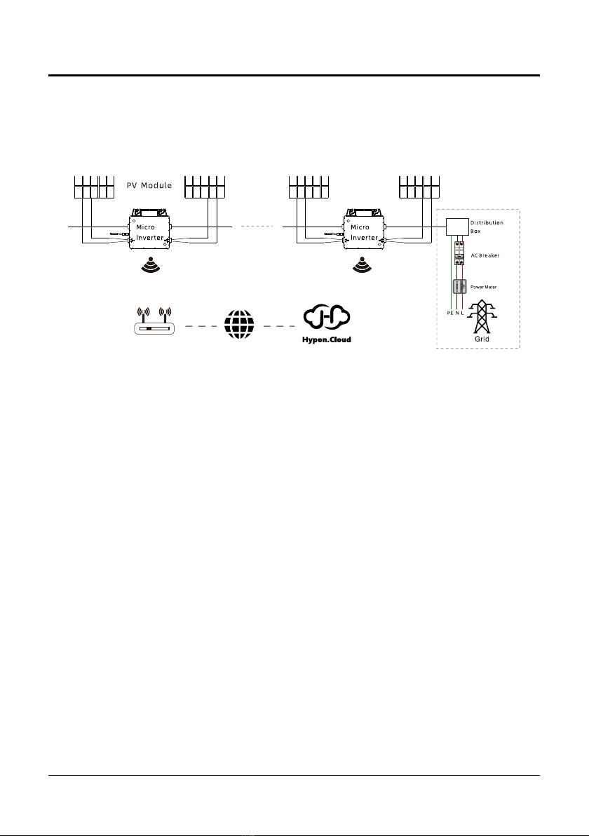
2. Micro Inverter System Introduction
The Micro Inverter is used in utility-interactive grid-tied applications, comprised of two
key elements:
Micro Inverter
Router
This integrated system improves safety; maximizes solar energy harvest;
increases system reliability, and simplifies solar system design, installation,
maintenance, and management.
Micro Inverters maximize PV energy production
The Micro Inverter ensures top performance from the array by maximizing the
performance of the module within the array when PV modules in the array are
affected by shading.
More reliable than centralized or string inverters
The distributed Micro Inverter system ensures that no single point of system
failure exists across the PV system. Micro Inverters are designed to operate at full
power at ambient temperatures of up to +65°C (+149° F). The inverter housing is
designed for outdoor installation and complies with the IP67 environmental
enclosure rating.

HMS-600W / 800W USER MANUAL 8
3. Working Mode
3.1 Work Mode
1. Normal: Under this mode, Micro Inverter is operating normally and convert DC
power into AC power to support the house loads and feed in to Public Grid.
2. Zero Export Control(optional,HM-2000D): Under this mode Micro Inverter’s
generation is limit base on the current house loads, there will be no extra power
feed in to the Public Grid.
3. Stand by: There are several circumstance that Micro Inverter will stay in Standby
mode:
- The current condition is contradicted with Micro Inverter operating requirement.
- No house loads or the Export control value has been set as “0” on the HM-2000D
under the Zero Export Control mode.
9 HMS-600W / 800W USER MANUAL
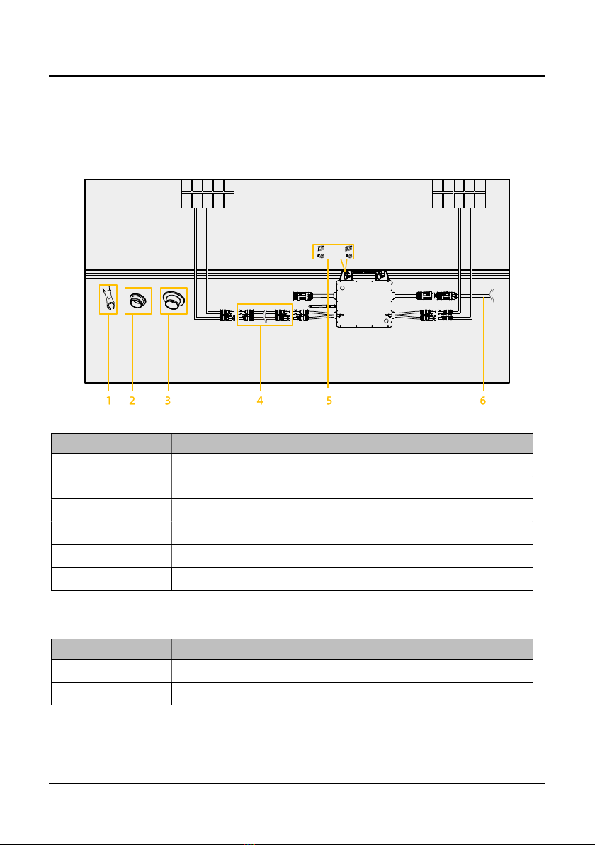
4. UNPACKING
3.1 Product Overview
The total size of HMS- 600W / 800W is 230(width) ×190(height) ×46.5(depth) mm. It
has 2 pairs of PV input terminals.
The detail description is shown below:
Note: None of the accessories above is included in the package and should be purchased
separately.
Mark Num. Description
1 MC4 Disassembly tool
2 AC male connector end cap
3 AC female connector end cap
4 DC Extension Cable
5 M8 screws(prepared by the installer-self)
6 AC Extension Cable
Model Maximum units per branch
HMS-600W 7
HMS-800W 5

HMS-600W / 800W USER MANUAL 10
5. INSTALLING
5.1 Installation Requirement
1. Planning the cable length Determine whether to use an extension cable.
2. Please install the inverter(s) in places that can avoid inadvertent contact.
3. The installation must be carried out with the equipment disconnected from the grid
(power disconnect switch open) and with the photovoltaic modules shaded or
isolated.
4. Installation method, location and surface must be fitting for the inverter’s weight and
dimensions.
5. The inverter performance peaks at ambient temperature lower than 65℃.
6. Avoid electromagnetic interference that can compromise the correct operation of
electronic equipment.
7. Install only on structures specifically conceived for photovoltaic modules (supplied by
installation technicians).
8. Install the Micro Inverter and all DC connections under the PV module to avoid direct
sunlight, rain exposure, snow buildup, UV, etc.
9. Install Micro Inverter underneath of the PV modules to make sure it works in the
shadow. If this condition cannot be met, might trigger the inverter production de-
rating.
This manual suits for next models
1
Table of contents
Other Hypontech Inverter manuals


