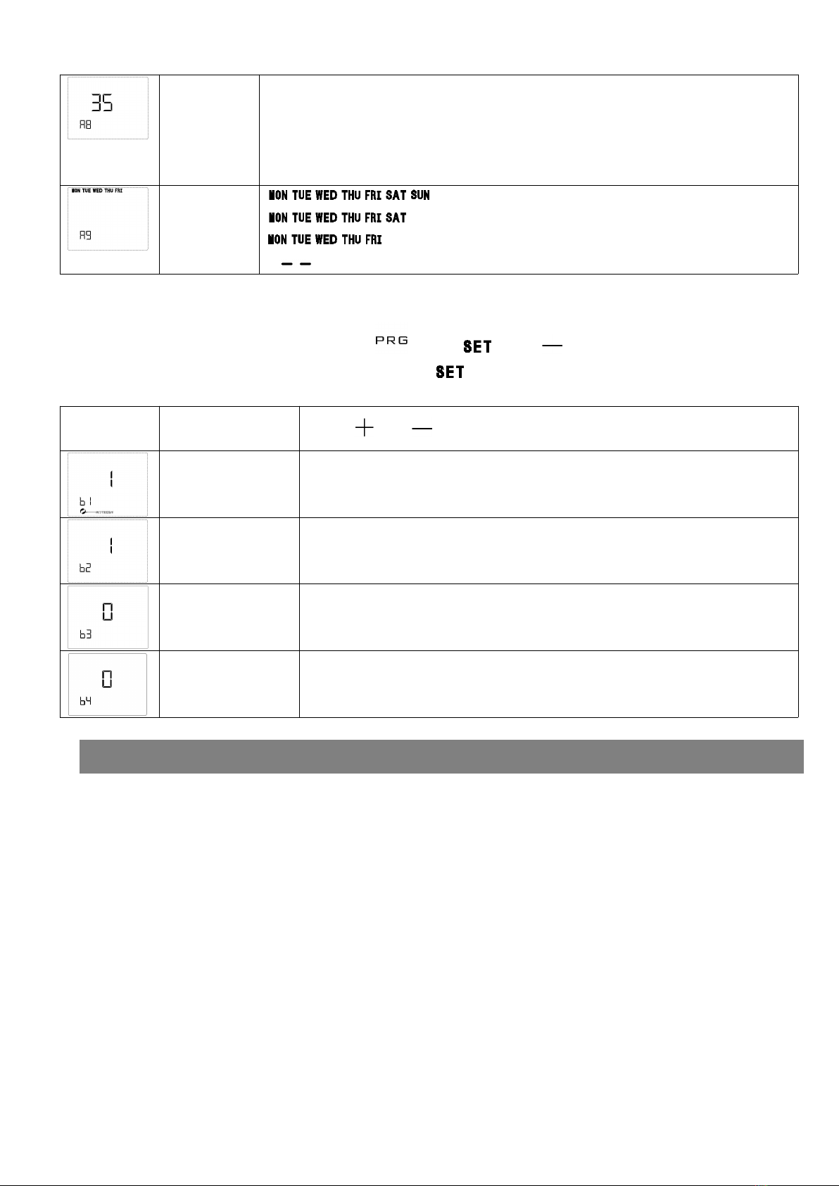
setting
temperature
highest
limiting value
(A8)
Range:30°C~70°C
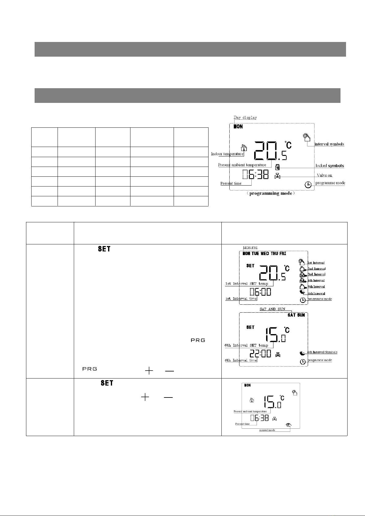
Week
programme
choice(A9)
: represent 7days programme
:represent6+1 programme
:represent5+2 programme
“ ”represent programme is canceled
2) MODE 2:
At power off state, hold down “ ”and “ ” and “ ”at the same time for 3
seconds it will display B1-B3,then press “ ” to switch between these options
Displaying
symbol
Option content
Press“ ”or“ ”to adjust value
Valve control option
(B1)
0 represent valve is controlled by the thermostat ;
1 represent valve is not controlled by the thermostat, it’s always closed。
Antifreezing Descaling
function)function
option(B2)
0 close,1 open。
Antifreezing function:when valve is continuously closed over100 hours,it will
be opened for3 minutes。
0=GA:valve switch protection time is about 3 seconds;
1=GB:valve switch protection time is about 15 seconds1;GB no antifreezing
function
°C Or °F(B4)Celsius degree or Fahrenheit degree
Cautions on Installation and Use:
1. To prevent the thermostat display from a high fluctuation, special treatment has been made to the program.
Therefore, it is normal that the thermostat cannot immediately display the sudden change of temperature.
2. The thermostat installed on 1.5m above the ground.
3. For the thermostat installed,please take care not to install it to the wall corner, door / window side or behind the
door or in such unheated area as exterior wall. Avoid hot / cold air duct, radiator, flue or thermal pipe
4. If the wireless thermostat with battery seat is placed at a position where the air ventilation is poor, the
temperature displayed on the thermostat might be inconsistent to the indoor average temperature.
5. Only the professional technicians are permitted to open the transmitting and receiving box of the thermostat
for installation. When installing the power supply, make sure that the power cable is well insulated.
6. To install the receiving box, please install the base plate firstly and then connect the power and signal wire
correctly before installing the upper cover and fix it. The thermostat is unrepairable product. The user shall
not open the internal circuit board.
7. Before installing the thermostat, make sure that the system is disconnected. The maximum voltage of the
system shall meet the requirements specified in the Instruction Manual (Max. AC Voltage: 250V).