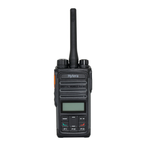
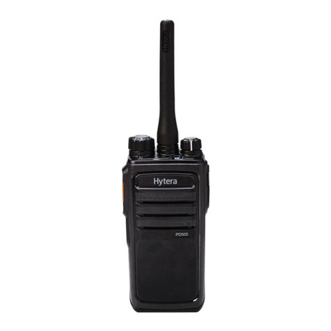
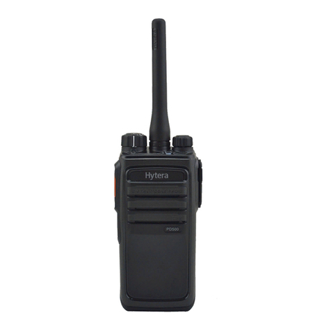
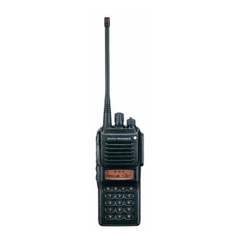
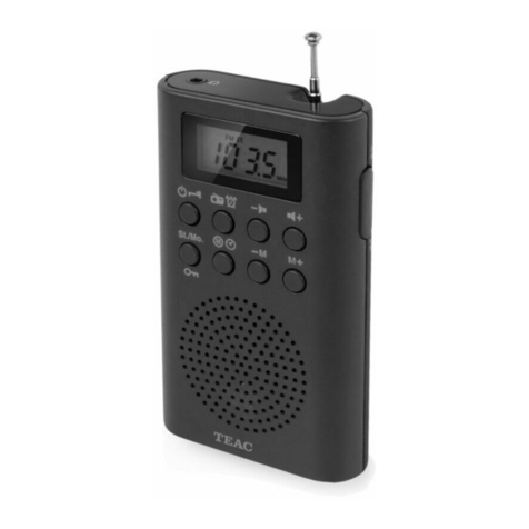
Hytera PD362 User manual

PORTABLE

Preface
This manual describes the information related to the product repair. It is intended for use by qualified
technicians only. To repair the product properly, please read this manual carefully before repairing.
This manual is applicable to the following product:
PD36X Digital Portable Radio (X may represent 2, 5, 6 or 8)

Copyright Information
Hytera is the trademark or registered trademark of Hytera Communications Corporation Limited (the
Company) in PRC and/or other countries or areas. The Company retains the ownership of its trademarks
and product names. All other trademarks and/or product names that may be used in this manual are
properties of their respective owners.
The product described in this manual may include the Company’s computer programs stored in memory
or other media. Laws in PRC and/or other countries or areas protect the exclusive rights of the Company
with respect to its computer programs. The purchase of this product shall not be deemed to grant, either
directly or by implication, any rights to the purchaser regarding the Company’s computer programs. Any
of the Company’s computer programs may not be copied, modified, distributed, decompiled, or
reverse-engineered in any manner without the prior written consent of the Company.
The AMBE+2TM voice coding technology embodied in this product is protected by intellectual property
rights including patent rights, copyrights and trade secrets of Digital Voice Systems, Inc. This voice
coding technology is licensed solely for use within this product. The user of this technology is explicitly
prohibited from attempting to decompile, reverse engineer, or disassemble the Object Code or in any
other way convert the Object Code into a human-readable format.
U.S. Patent No: #6,912,495 B2, #6,199,037 B1, #5,870,405, #5,826,222, #5,754,974, #5,701,390,
#5,715,365, #5,649,050, #5,630,011, #5,581,656, #5,517,511, #5,491,772, #5,247,579, #5,226,084 and
#5,195,166.
Disclaimer
Hytera Communications Corporation Limited (the Company) endeavors to achieve the accuracy and
completeness of this manual, but no warranty of accuracy or reliability is given. All the specifications and
designs are subject to change without notice due to continuous technology development. No part of this
manual may be copied, modified, translated, or distributed in any manner without the express written
permission of us.
We do not guarantee, for any particular purpose, the accuracy, validity, timeliness, legitimacy or
completeness of the Third Party products and contents involved in this manual.
If you have any suggestions or would like to learn more details, please visit our website at:
http://www.hytera.com.
Documentation Information
Conventions
Icon Conventions
Icon Description
Tip Indicates information that can help you make better use of your product.

Note Indicates references that can further describe the related topics.
Caution Indicates situations that could cause data loss or equipment damage.
Warning Indicates situations that could cause minor personal injury.
Danger Indicates situations that could cause major personal injury or even death.
Notation Conventions
Notation Description
“ ”
The quotation marks enclose the name of a software interface element. For
example, click “OK”.
Bold
The text in boldface denotes the name of a hardware button. For example, press the
PTT key.
->
The symbol directs you to access a multi-level menu. For example, to select “New”
from the “File” menu, we will describe it as follows: “File -> New”.
Revision History
Version Release Date Description
V00 10-2014
Initial Release. This manual includes the information of
these frequency bands:
Ua
Uc

Ua (400‐440 MHz)

Ua (400
‐
440 MHz)
Contents
i
Contents
1. Product Controls .................................................................................................................................. 1
2. Disassembly and Assembly................................................................................................................ 3
3. Exploded View and Packaging Guide................................................................................................ 7
3.1 Exploded View .................................................................................................................................. 7
3.2 Packaging Guide .............................................................................................................................. 9
4. Specifications ..................................................................................................................................... 10
5. Circuit Description ............................................................................................................................. 12
5.1 Baseband........................................................................................................................................ 12
5.1.1 Power Supply Module .......................................................................................................... 12
5.1.2 Control Module ..................................................................................................................... 15
5.1.3 Audio Module........................................................................................................................ 16
5.2 RF Section ...................................................................................................................................... 17
5.2.1 Transmitter Circuit ................................................................................................................ 17
5.2.2 Receiver Circuit .................................................................................................................... 19
5.2.3 FGU ...................................................................................................................................... 20
6. Troubleshooting Flow Chart ............................................................................................................. 22
6.1 Control Circuit ................................................................................................................................. 22
6.1.1 No display upon power-on or abnormal display................................................................... 22
6.1.2 No voice output by speaker.................................................................................................. 23
6.1.3 No modulation signal in transmission .................................................................................. 24
6.2 Receiver Circuit .............................................................................................................................. 25
6.3 Transmitter Circuit .......................................................................................................................... 26
6.4 FGU Circuit ..................................................................................................................................... 29
7. Interface Definition............................................................................................................................. 31
8. Tuning Description............................................................................................................................. 32
8.1 Tools ............................................................................................................................................... 32
8.2 Tuning Procedure ........................................................................................................................... 32
8.2.1 Tuning a radio....................................................................................................................... 32
8.2.2 Testing a radio ...................................................................................................................... 35
9. PCB View............................................................................................................................................. 36
10. Block Diagram .................................................................................................................................. 37
10.1 Radio General Diagram................................................................................................................ 37
10.2 RF Circuit...................................................................................................................................... 38
10.3 Baseband Circuit .......................................................................................................................... 39
10.4 Power Supply Circuit .................................................................................................................... 40
10.5 FGU Circuit ................................................................................................................................... 41
10.6 Receiver Circuit ............................................................................................................................ 42

Contents
Ua (400
‐
440 MHz)
ii
10.7 Transmitter Circuit ........................................................................................................................ 43
11. Schematic Diagram.......................................................................................................................... 44
12. Parts List ........................................................................................................................................... 54

Ua (400
‐
440 MHz)
Product Controls
1
1. Product Controls
No. Part Name No. Part Name
○
1 PTT (Push-to-Talk) Key ○
13 LED Indicator
○
2 SK1 (Side Key 1) ○
14 Microphone
○
3 Antenna ○
15 Cancel/Return Key
○
4 Speaker ○
16 Volume +/Right Key
○
5 LCD Display ○
17 Power On/Off/ESC Key
○
6 OK/Menu Key ○
18 P3 Key
○
7 Up Key ○
19 Down Key
○
8 Volume -/Left Key ○
20 Charging/Data Connector
○
9 Call Key ○
21 Earpiece Connector

Product Controls
Ua (400
‐
440 MHz)
2
No. Part Name No. Part Name
○
10 P1 Key ○
22 Battery Cover Open-up
○
11 P2 Key ○
23 Battery Cover
○
12 Strap Hole / /

Ua (400
‐
440 MHz)
Disassembly and Assembly
3
2. Disassembly and Assembly
This section is designed to introduce the way to disassemble the radio. To assemble the radio, do vice
versa.
Caution
Please position the waterproof ring properly during reassembly.
Use the thumb and index finger to move the silicon rubber of SK1 key until SK1 key is well
assembled.
Step 1 To remove the battery, do as follows.
Step 2 Remove the chassis.
Remove the four T6 screws and take out the chassis.

Disassembly and Assembly
Ua (400
‐
440 MHz)
4
Step 3 Remove the main board.
1. First unplug the speaker connector and Keypad FPC connector, and then remove the one
T6 screw.
2. Take out the main board in the direction shown in the figure below.
Step 4 Remove the keypad board.
3. Remove the two screws on the back.

Ua (400
‐
440 MHz)
Disassembly and Assembly
5
4. Remove the keypad board.
Step 5 Remove the LCD display.
5. Straighten the two fixing plates securing the LCD display. See the figure below.
6. Take out the LCD display vertically.

Disassembly and Assembly
Ua (400
‐
440 MHz)
6
Step 6 Remove the aluminum chassis shielding cover.
7. Remove the three screws securing the aluminum chassis shielding cover.
8. Take out the aluminum chassis shielding cover.

Ua (400
‐
440 MHz)
Exploded View and Packaging Guide
7
3. Exploded View and Packaging Guide
3.1 Exploded View
Parts list:
No.
Part No. Description Qty.
No.
Part No. Description Qty.
1
7500801000000
PORON
2 26 7400628000000 Speaker felt
1
2
6002127000000
Chassis 1 27 6002144000000 Stopper for earpiece
connector cover 2
3
7500512000000
Motor PORON pad
1 28 6002113000000 Earpiece connector cover
1
4
7500809000000
Conductive sponge for aluminum
chassis
1
29 6002124000000
Micro USB cover 1
5
7400656000000
Earpiece PC sheet
1
30
6002126000000
Front case
1
6
/
PCB main board
1
31
7500717000000
Motor PORON
1
7
7500724000000
LCD PORON pad
1
32
6002128000000
Antenna cover
1
8
7102002500000
Machine screw M2.0x2.5mm 2
33 6101008000000
Transparent silicon rubber
light guide
1
9
7500376000010
Conductive sponge for earpiece
FPC
1
34 4200040000300
Power Cord 1
10
6203684000000
Decoration sheet (right side)
1
35
5001000000090
Speaker
1
11 / Model PC label 18x7mm 1
36 7500784000000
Insulative PORON for
speaker
1

Exploded View and Packaging Guide
Ua (400
‐
440 MHz)
8
No.
Part No. Description Qty.
No.
Part No. Description Qty.
12
6203683000000
Decoration sheet (bottom side)
1
37
/
Antenna core
1
13
7500305000000
PORON pad for connector 1
38 6101083100000
Silicon rubber pad for battery
connector
1
14
7600052000000
Conductive sponge for front case 1
39 7101904020200
Self-tapping Screw
ST1.9*4.0mm
3
15
7500749000000
Double-sided adhesive tape for
keypad FPC 1
40 7400141000000
NSM08Z01 MIC felt 1
16
/
Semi-finished keypad board
1
41
7400329000000
MIC pad
1
17
7300122000000
Metal dome for functional key
1
42
5002270000030
Microphone
1
18
7500748000000
Double-sided adhesive tape for
LCD lens 1
43 6300253000000
Aluminum chassis shielding
cover
1
19
6101009000000
P&R keypad
1
44
6101018100000
Silicon rubber pad for battery
4
20
6002125000000
LCD lens 1
45 6101059100000
Silicone rubber plug for RF
test port
1
21
6203685000000
Decoration sheet (left side)
1
46
6101023100000
Main waterproof ring
1
22
6002110000000
PTT key cover
1
47
6101022100000
Waterproof ring for battery
1
23
6101052100000
PTT key (silicone rubber)
1
48
6002129000000
Battery Cover
1
24
6203682000000
Speaker steel felt 1
49 / PC label with LOGO
19.7x4.8mm 1
25
7500756000000
Double-sided adhesive tape for
speaker steel felt 1
50 6002132000000
BC21 belt clip 1
Note
Parts that are not marked with Part Number may vary with the frequency band.

Ua (400
‐
440 MHz)
Exploded View and Packaging Guide
9
3.2 Packaging Guide

Specifications
Ua (400
‐
440 MHz)
10
4. Specifications
General
Frequency Range 400‐440 MHz
Channel Capacity 256
Channel Spacing 25 kHz/12.5 kHz
Operating Voltage
Rated voltage: 3.7 V
Extreme voltage: 3.15–4.2V
Battery 2000 mAh Li-Ion battery
Battery Life (5-5-90 Duty Cycle,
High TX Power)
High-capacity 2000mAh Li-Ion
Battery
Analog: 10 hours
Digital: 12 hours
Operating Temperature -30°C to +60°C
Dimensions (H×W×D)
(with standard battery, without
antenna)
106 mm × 57 mm × 23 mm
Weight (with antenna &
standard battery)
About 180 g
Frequency Stability ±0.5 ppm
Receiver
Sensitivity
Analog
0.28 μV (12 dB SINAD)
0.22 μV (Typical) (12 dB SINAD)
0.22 μV (20 dB SINAD)
Digital: -116 dBm/BER5%
Adjacent Channel Selectivity
TIA-603: 60 dB@12.5 kHz/70 dB@25 kHz
ETSI: 60 dB@12.5 kHz/70 dB@25 kHz
Intermodulation
TIA-603: 70 d[email protected]/25 kHz
ETSI: 65 dB@12.5/25 kHz
Spurious Response Rejection
TIA-603: 70 d[email protected]/25 kHz
ETSI: 70 d[email protected]/25 kHz
Blocking 84 dB

Ua (400
‐
440 MHz)
Specifications
11
Note
All Specifications are tested according to applicable standards, and subject to change without notice
due to continuous development.
Rated Audio Power Output 0.4 W (8 Ω load)
Rated Audio Distortion ≤5%
Transmitter
Power Output 3 W/1.5 W
Conducted/Radiated Emission
-36 dBm<1 GHz
-30 dBm>1 GHz
Modulation Limiting
±2.5 kHz@12.5 kHz
±5.0 kHz@25 kHz
FM Noise
40 [email protected] kHz
45 dB@25 kHz
Audio Distortion ≤3%

Circuit Description
Ua (400
‐
440 MHz)
12
5. Circuit Description
5.1 Baseband6HFWLRQ
CODEC
TLV320AIC3204
STM32F101VET6
AMP
MAX9716EUA
MCLK
BCLK
WCLK
DIN
DOUT
MCLK
VDD3V3
12.288MHZ
SCL
SDA
Security Key
I2S
HPI
VOICE
CODER
Protoccol
Stack 4FSK
FM
Demod
Channel
Selection
SCT3928
S0CLK
S0FS
S0DO
S0DI
S1CLK
S1FS
S1DO
S1DI
CLKIN
SCL
SDA
FLASH_CLK
FLASH_CE
FLASH_DI
FLASH_DO
MCU
PLL_CLK
PLL_STB
PLL_DATA
PLL_LD
MOD_VCO
MOD_REF
AFDET
SQL
RSSI
BAT_DET
APC/TV
ADJ_CRY
Volume
adjust
BEEP
3V0A
BAT
T/R
SW-CVread
BIAS_DOWN
RSSI
PTT
12MHZ
OPT_SEL
R/G
RESET 3V3D
W/N
EEPROM
24FC512-I/SM
I2C
3V3D
3V0D 1V2
LOR
LOL
IN3R
IN1L
HPL
IN2L
AF_MUTE
AF_MUTE
USART port
VOX
VOX
EXT_interface
ext_mic
ext_spk
V_CHARGER
LCD
LCD_RSTB
LCD_CSB
LCD_SDA
LCD_SCLK
A0
5.1.1 Power Supply Module
Diagram of Power Control
The power supply employs a single 3.7V li-ion battery. The RF section uses LDO to regulate WKHYROWDJHWR 3V
for FGU and PLL circuits and the control parts of RX and TX circuits. The BB section uses ORZGURSRXW/'2
to regulate WKHYROWDJHWR 3V for Codec, MCU and SCT3928. The core power supply of SCT3928 uses
DC/DC to convert the voltage to 1.2V.

Ua (400
‐
440 MHz)
Circuit Description
13
3 VRT
U301
LDO
RP102N301B
P WR- KEY_ DET
To PLL
SCT3928
PWR_ON
POWER_ON
U302
LDO
RP102N301B
U307
LDO
RP102N301B
DTC114YE
U310
DC-DC
TPS62561DDCR
3V0A
3V0D
A
3V0
U308
LDO
RP102N301B
POWER_ON
POWER_ON
POWER_ON
POWER_ON
PWR_STC3V
U306
LDO
RP102N301B
EM6M2
VDD_OP
To APC
To autio PA
To RF PA
To APC REF
VBAT
TP609
U608
CHARGER
MC 34673
CHG
VBUS
PPP
After inserted the charger, wake
up the walky-talky
Read charger status
Detect charger inserted
EM6M2
EM6M2
3V_TX_RF
3V_ RX_RF
TEM- LEV- DET- TC
TX_EN
RX_EN
To SCT 3928,U203( Security Key), crystal, Codec
To LED
To SCT3928
To_ EEPROM
To MCU
To Codec LDOIN
RESET
To Mic amp
RESET
R 3112Q 271A
POWER_ KEY-
POWER_ KEY-
To keypad( hardware connectted)
DC2DC_ CTRL
To VCO
To FAST LOCK
VCC_VC_ TCXO
3V0_ FGU_ PER
VCC_CP
DTC114YE
CHG_ CURRENT
ISET
U309
XC6118N28
AMR-G
3V FGU
U304
LDO
RP102Z301D
1V2D
To LCD
VCO buffer and amp.
POWER_ON
TX_EN
LED_LCD_ BL
Powering On/ Off
This manual suits for next models
3
Table of contents
Other Hytera Portable Radio manuals

Hytera
Hytera PD702i User manual

Hytera
Hytera PD412 User manual

Hytera
Hytera BD51X User manual

Hytera
Hytera TETRA PT580H User manual

Hytera
Hytera PD502 User manual

Hytera
Hytera PD50X User manual

Hytera
Hytera TC610 User manual

Hytera
Hytera PD48X User manual

Hytera
Hytera PD715 Rx User manual

Hytera
Hytera X1e User manual

Hytera
Hytera BD51XU1 User manual

Hytera
Hytera PD502 User manual

Hytera
Hytera PD98X User manual

Hytera
Hytera PD562i UL913 User manual

Hytera
Hytera BD50X User manual

Hytera
Hytera HP68X User manual

Hytera
Hytera PD56X R5.6 User manual

Hytera
Hytera HP31X User manual

Hytera
Hytera PD782iG User manual

Hytera
Hytera F-412 User manual