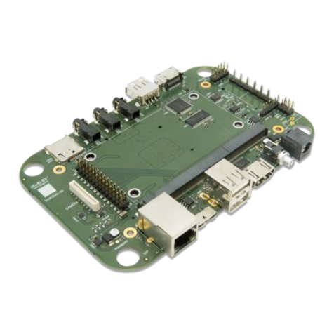
i-See IGEP SMARC iMX6 Application guide

IGEPTM SMARC iMX6
Hardware Reference Manual
ISEE 2007 S.L. All rights reserved, IGEP is a registered trademark from ISEE 2007 S.L. The following is provided for informational purposes only.
NIF:ESB64377005 Document: MAN-IGEP0046-001 / Revision: 1.3 / Date: 23/06/2016
2
Table of contents
Table of contents 2
1USER INFORMATION 4
1.1 ABOUT THIS DOCUMENT 4
1.2 COPYRIGHT NOTICE 4
1.3 TRADEMARKS 4
1.4 STANDARDS 4
1.5 WARRANTY 4
1.6 TECHNICAL SUPPORT 5
2INTRODUCTION 6
2.1 PRODUCT DESCRIPTION 6
2.2 IGEPTM SMARC iMX6 BENEFITS AND APPLICATIONS 7
2.3 The IGEPTM SMARC iMX6 SERIES 7
2.4 ORDERING INFORMATION 8
2.5 EXPANSION BOARDS 8
3OVERVIEW 9
3.1 IGEPTM SMARC iMX6 9
3.2 IGEPTM SMARC iMX6 FEATURES 10
3.3 IGEPTM SMARC iMX6 VARIANTS 11
3.4 iMX6 ARM CORTEX-A9 PROCESSORS 12
4PRODUCT SPECIFICATION 13
4.1IGEPTM SMARC iMX6 BLOCK DIAGRAM 13
4.2 POWER SOURCES 14
4.3 CONTROL SIGNALS 15
4.4 ETHERNET 17
4.5 USB CONNECTIONS 19
4.6 I2C: INTER-INTEGRATED CIRCUIT INTERFACE 21
4.7 PWM: PULSE-WIDTH MODULATION 22
4.8 SPI: SERIAL PERIPHERAL INTERFACE 23
4.9 MMC: MULTI MEDIA CARD INTERFACE 24
4.10 UART: UNIVERSAL ASYNCHRONOUS RECEIVER-TRANSMITTER 25
4.11 CAN BUS: CONTROLLER AREA NETWORK 27
4.12 I2S: SERIAL AUDIO PORT 28
4.13 GPIO: GENERAL PURPOSE INPUT OUTPUT 29

IGEPTM SMARC iMX6
Hardware Reference Manual
ISEE 2007 S.L. All rights reserved, IGEP is a registered trademark from ISEE 2007 S.L. The following is provided for informational purposes only.
NIF:ESB64377005 Document: MAN-IGEP0046-001 / Revision: 1.3 / Date: 23/06/2016
3
4.14 SATA 30
4.15 PCIe 31
4.16 MIPI CSI 32
4.17 MIPI DSI 33
4.18 LVDS 33
4.19 HDMI 34
4.20 SUPERVISOR 35
4.21 ENVIRONMENTAL SPECIFICATION 35
4.22 STANDARDS AND CERTIFICATIONS 35
4.23 MTBF 36
4.24 MECHANICAL SPECIFICATION 37
5ON-BOARD INTERFACES 38
5.1 SUMMARY 38
5.2 LEDs 38
5.3 JTAG 39
6SMARC-314 EXPANSION CONNECTOR INTERFACE 40
6.1 PINOUT TABLE OF SMARC-314 EXPANSION INTERFACE 42
7ELECTRICAL CHARACTERISTICS 52
8LIST OF TABLES 53
9LIST OF FIGURES 53
10 CHANGE HISTORY 54

IGEPTM SMARC iMX6
Hardware Reference Manual
ISEE 2007 S.L. All rights reserved, IGEP is a registered trademark from ISEE 2007 S.L. The following is provided for informational purposes only.
NIF:ESB64377005 Document: MAN-IGEP0046-001 / Revision: 1.3 / Date: 23/06/2016
4
1USER INFORMATION
1.1 ABOUT THIS DOCUMENT
This document provides information about products from ISEE 2007 SL and/or its subsidiaries. No warranty of
suitability, purpose, or fitness is implied. While every attempt has been made to ensure that the information
in this document is accurate, the information contained within is supplied “as-is” and is subject to change
without notice.
For the circuits, descriptions and tables indicated, ISEE 2007 SL assumes no responsibility as far as patents or
other rights of third parties are concerned.
1.2 COPYRIGHT NOTICE
This document is copyrighted, 2013-2016, by ISEE 2007 SL.
All rights are reserved. ISEE reserves the right to make improvements to the products described in this
manual at any time without notice. No part of this manual may be reproduced, copied, translated or
transmitted in any form or by any means without the prior written permission of the original manufacturer.
Information provided in this manual is intended to be accurate and reliable. However, the original
manufacturer assumes no responsibility for its use, nor for any infringements upon the rights of third parties,
which may result from its use.
1.3 TRADEMARKS
IGEPTM ® is trademark of ISEE. ISEE is trademark or registered trademark of ISEE 2007 SL.
Product names, logos, brands and other trademarks featured or referred to within this user’s guide, or the
ISEE website, are the property of their respective trademark holders. These trademark holders are not
affiliated with ISEE, our products or our website.
1.4 STANDARDS
ISEE 2007 S.L. is going to be certified to ISO 9001:2015
1.5 WARRANTY
THE FOREGOING WARRANTY IS THE EXCLUSIVE WARRANTY MADE BY SELLER TO BUYER AND IS IN
LIEU OF ALL OTHER WARRANTIES, EXPRESSED, IMPLIED, OR STATUTORY, INCLUDING ANY
WARRANTY OF MERCHANTABILITY OR FITNESS FOR ANY PARTICULAR PURPOSE.
The user assumes all responsibility and liability for proper and safe handling of the goods. Further, the user
indemnifies ISEE 2007 SL from all claims arising from the handling or use of the goods. Due to the open
construction of the product, it is the user’s responsibility to take any and all appropriate precautions with
regard to electrostatic discharge.
EXCEPT TO THE EXTENT OF THE INDEMNITY SET FORTH ABOVE, NEITHER PARTY SHALL BE LIABLE
TO THE OTHER FOR ANY INDIRECT, SPECIAL, INCIDENTAL, OR CONSEQUENTIAL DAMAGES.
ISEE 2007 SL currently deals with a variety of customers for products, and therefore our arrangement with the
user is not exclusive. ISEE assumes no liability for applications assistance, customer product design, software
performance, or infringement of patents or services described herein.

IGEPTM SMARC iMX6
Hardware Reference Manual
ISEE 2007 S.L. All rights reserved, IGEP is a registered trademark from ISEE 2007 S.L. The following is provided for informational purposes only.
NIF:ESB64377005 Document: MAN-IGEP0046-001 / Revision: 1.3 / Date: 23/06/2016
5
Please read specifically, the Warnings and Restrictions notice in this manual prior to handling the product.
This notice contains important safety information about temperatures and voltages. For additional
information on IGEPTM environmental and/or safety programs, please contact with ISEE
(support@iseebcn.com).
No license is granted under any patent right or other intellectual property right of ISEE covering or relating to
any machine, process, or combination in which such ISEE products or services might be or are used.
NOTE: It could be found a detailed warranty and sales conditions of IGEPTM on ISEE website: https://www.isee.biz
1.6 TECHNICAL SUPPORT
Technicians and engineers from ISEE 2007 SL and/or its subsidiaries are available for technical support. We
are committed to make our product easy to use and will help you use our products in your systems.
Please consult our Website at https://www.isee.biz for the latest product documentations: hardware
resources (schematics, mechanical drawings, layouts, etc.) and software resources (firmware binaries and
sources). You can also contact directly with our Technical Department and we will assist you with any queries
or problems you may have (support@iseebcn.com).

IGEPTM SMARC iMX6
Hardware Reference Manual
ISEE 2007 S.L. All rights reserved, IGEP is a registered trademark from ISEE 2007 S.L. The following is provided for informational purposes only.
NIF:ESB64377005 Document: MAN-IGEP0046-001 / Revision: 1.3 / Date: 23/06/2016
6
2INTRODUCTION
2.1 PRODUCT DESCRIPTION
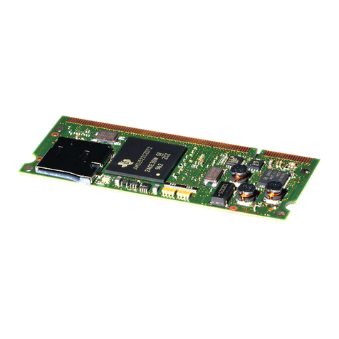
The IGEPTM SMARC iMX6 is an industrial low computer module based on ARM Cortex-A9 at speeds up to 1.2
GHz by NXP Semiconductors iMX6 family of processors.
It’s an industrial computer platform (it can work in a temperature range from -40 ºC to +85 ºC), in a low profile
(its dimensions are only 82 mm x 50 mm). With different combinations of RAM and Flash memory (see the
customized possibilities at chapter 2.4), a complete list of interfaces and peripherals, and with the possibility
to have a 3D graphic accelerator, it can be the base for complex industrial equipment or any other kind of
application.
There is also an expansion board (IGEPTM SMARC EXPANSION) to complement the module. It’s a developer
baseboard and it can be used as the fastest way to test the final application before the prototyping phase.
Highlights:
Fully tested, highly reliable, scalable, efficient and high performing board that allows customers to
focus on their end application.
Designed for industrial range purposes (temperature range: -40 ºC to +85 ºC).
With its compact design and extended temperature range. It’s adaptable to any custom baseboard.
Easy connectivity through the SMARC-314 connector. Small form factor size (82 mm x 50 mm).
1V8 I/O level signals.
JTAG interface available.
It is based on NXP Semiconductors iMX6 processor which has an advanced Cortex-A9 ARM
Architecture.
The iMX6 Family processors are based on the enhanced device architecture and include the NEON
TM Media coprocessor.
This architecture of high performance applications processor is designed to provide best in class ARM
and graphics performance while delivering low power consumption.
Gigabit Ethernet Physical Layer Transceiver (PHY).
WiFi IEEE 802.11 a/b/g/n with Access Point.
Bluetooth v4.0 (BLE).
Flexible Memory of Flash Memory combinations (customized option).

IGEPTM SMARC iMX6
Hardware Reference Manual
ISEE 2007 S.L. All rights reserved, IGEP is a registered trademark from ISEE 2007 S.L. The following is provided for informational purposes only.
NIF:ESB64377005 Document: MAN-IGEP0046-001 / Revision: 1.3 / Date: 23/06/2016
7
2.2 IGEPTM SMARC iMX6 BENEFITS AND APPLICATIONS
There are a lot of advantages that developers will find in the IGEPTM SMARC iMX6 series. On board terms, it’s
a more friendly way to achieve your projects. Amongst others, the main benefits are the following:
Compact and powerful core for new products.
Robust and easy to mount due to the SMARC 314 connector.
Reduced time to market.
Low power consumption ≤6W.
Commercial and Industrial Temperature Range 0 ºC to +60 ºC and -40 ºC to +85 ºC.
Extended life range product (min 10 years).
At the same time, it can be implemented in all kind of end applications. The followings are just a few ones, but
the list can be as long as the imagination of the developers.
Connected vending machines.
Home / Building automation.
Human Interface.
Industrial Control.
Test and Measurement.
2.3 The IGEPTM SMARC iMX6 SERIES
The IGEPTM SMARC iMX6 series is composed by four models. They are all made with the same care and
quality that ISEE customers already know and trust.
The models have the same general circuit but they change in the CPU used (available models: iMX6Solo,
iMX6DualLite, iMX6Dual and iMX6Quad), the RAM memory (512MB, 1GB or 2GB) and the storage memory
(eMMC flash).
In the chapter 3.3 are commented the main differences according to processor model.

IGEPTM SMARC iMX6
Hardware Reference Manual
ISEE 2007 S.L. All rights reserved, IGEP is a registered trademark from ISEE 2007 S.L. The following is provided for informational purposes only.
NIF:ESB64377005 Document: MAN-IGEP0046-001 / Revision: 1.3 / Date: 23/06/2016
8
2.4 ORDERING INFORMATION
IGEPTM Device
Model Reference
Description
IGEPTM SMARC iMX6Solo
IGEP-SMARC-iMX6S-512M-4G-W-E
Processor: iMX6 Solo
RAM Memory: 512 MB DDR3 SDRAM
Storage: 4 GB eMMC
IGEPTM SMARC iMX6DualLite
IGEP-SMARC-iMX6DL-1G-4G-W-E
Processor: iMX6 DualLite
RAM Memory: 1 GB DDR3 SDRAM
Storage: 4GB eMMC
IGEPTM SMARC iMX6Dual
IGEP-SMARC-iMX6D-2G-8G-W-E
Processor: iMX6 Dual
RAM Memory: 2 GB DDR3 SDRAM
Storage: 8 GB eMMC
IGEPTM SMARC iMX6Quad
IGEP-SMARC-iMX6Q-2G-8G-W-E
Processor: iMX6 Quad
RAM Memory: 2 GB DDR3 SDRAM
Storage: 8 GB eMMC
Table 1 Ordering information
2.5 EXPANSION BOARDS
All the products in the IGEPTM SMARC iMX6 series can be supplemented with next expansion boards.
IGEPTM Device
Model Reference
Description
IGEPTM SMARC EXPANSION
BASE0040-RBxx
Designed for fast prototyping of user’s projects
Table 2 Expansion boards

IGEPTM SMARC iMX6
Hardware Reference Manual
ISEE 2007 S.L. All rights reserved, IGEP is a registered trademark from ISEE 2007 S.L. The following is provided for informational purposes only.
NIF:ESB64377005 Document: MAN-IGEP0046-001 / Revision: 1.3 / Date: 23/06/2016
9
3OVERVIEW
3.1 IGEPTM SMARC iMX6
Figure 1 IGEPTM SMARC iMX6 Top View
Figure 2 IGEPTM SMARC iMX6 Bottom View

IGEPTM SMARC iMX6
Hardware Reference Manual
ISEE 2007 S.L. All rights reserved, IGEP is a registered trademark from ISEE 2007 S.L. The following is provided for informational purposes only.
NIF:ESB64377005 Document: MAN-IGEP0046-001 / Revision: 1.3 / Date: 23/06/2016
10
3.2 IGEPTM SMARC iMX6 FEATURES
Feature
IGEP SMARC
iMX6Quad
IGEP SMARC
iMX6Dual
IGEP SMARC
iMX6DualLite
IGEP SMARC
iMX6Solo
ARM CPU
4x NXP iMX6 ARM
Cortex–A9TM up to
1.2GHz
L1 Instruction cache:
32 KB per core
L1 Data cache: 32 KB
per core
L2 cache: 1 MB
NEONTM SIMD
Coprocessor per core
PTM per core
2x NXP iMX6 ARM
Cortex–A9TM up to
1.2GHz
L1 Instruction cache:
32 KB per core
L1 Data cache: 32 KB
per core
L2 cache: 1 MB
NEONTM SIMD
Coprocessor per core
PTM per core
2x NXP iMX6 ARM
Cortex–A9TM up to
1GHz
L1 Instruction cache: 32
KB per core
L1 Data cache: 32 KB per
core
L2 cache: 512 KB
NEONTM SIMD
Coprocessor per core
PTM per core
1x NXP iMX6 ARM
Cortex–A9TM up to
1GHz
L1 Instruction cache:
32 KB
L1 Data cache: 32 KB
L2 cache: 512 KB
NEONTM SIMD
Coprocessor
PTM
2D/3D graphics
acceleration
Vivante GC2000 GPU 3D
Vivante GC320 GPU 2D (Composition)
Vivante GC355 GPU 2D (Vector Graphics)
OpenGL ES 3.0, OpenCL 1.1 EP and Open VG
1.1 support
Vivante GC880 GPU 3D
Vivante GC320 GPU 2D (Composition)
GPU 2D (Vector Graphics) emulated on GPU 3D
OpenGL ES 2.0 support
Video
acceleration
Video acceleration: H.264, H.263, MPEG-2 and
MPEG-4
Video encoder/decoder dual 1080p @ 60 fps
2x IPU
Video acceleration: H.264, H.263, MPEG-2 and
MPEG-4
Video encoder/decoder 1080p @ 60 fps
1x IPU
Camera
Interface
MIPI CSI-2 (4 lanes)
MIPI CSI-2 (2 lanes)
Table 3 IGEPTM SMARC iMX6 Processor
Feature
Specifications
RAM Memory
256 MB up to 4 GB DDR3-1066 SDRAM
Storage
No flash up to 64 GB eMMC
Table 4 Memory and Storage
Feature
Specifications
Power to SMARC-314 connector
Supply Voltage (VIN) from 4.75 V to 5.25 V DC
Table 5 Power

IGEPTM SMARC iMX6
Hardware Reference Manual
ISEE 2007 S.L. All rights reserved, IGEP is a registered trademark from ISEE 2007 S.L. The following is provided for informational purposes only.
NIF:ESB64377005 Document: MAN-IGEP0046-001 / Revision: 1.3 / Date: 23/06/2016
11
Feature
Specifications
Interfaces
1 x SMARC-314 expansion interface
1 x JTAG interface
Devices
1 x Double LED indicator:
Red LED for user application
Green LED for user application
1 x 10/100/1000 Mbps Ethernet PHY interface
1 x eMMC flash interface
1 x WiFi IEEE 802.11 a/b/g/n with Access Point
1 x Bluetooth v4.0
1 x SPI NOR flash
1 x EEPROM
Table 6 On-board interfaces and devices
3.3 IGEPTM SMARC iMX6 VARIANTS
The IGEPTM SMARC iMX6 modules are based in ARM Cortex-A9 processors, and the concrete devices used are
the NXP iMX6 Family. For this reason, the modules may be provided with several processors options and,
each one of them have different characteristics. In the next figure are reflected all the options of processor
used in the different configurations of IGEPTM SMARC iMX6 with its differences. The customized possibilities
are collected in the chapter 2.4 (Ordering Information). Contact with sales@iseebcn.com for more
information.
Figure 3 NXP iMX6Family Features

IGEPTM SMARC iMX6
Hardware Reference Manual
ISEE 2007 S.L. All rights reserved, IGEP is a registered trademark from ISEE 2007 S.L. The following is provided for informational purposes only.
NIF:ESB64377005 Document: MAN-IGEP0046-001 / Revision: 1.3 / Date: 23/06/2016
12
3.4 iMX6 ARM CORTEX-A9 PROCESSORS
The iMX6, by NXP, are a family of highly integrated microprocessors based on the ARM Cortex-A9 processor.
They have a high performance at low cost and are delivered with 3D graphics acceleration and key
peripherals. They also support different high-level operating systems (Linux and Android).
Figure 4 iMX6 processors Block Diagram

IGEPTM SMARC iMX6
Hardware Reference Manual
ISEE 2007 S.L. All rights reserved, IGEP is a registered trademark from ISEE 2007 S.L. The following is provided for informational purposes only.
NIF:ESB64377005 Document: MAN-IGEP0046-001 / Revision: 1.3 / Date: 23/06/2016
13
4PRODUCT SPECIFICATION
4.1 IGEPTM SMARC iMX6 BLOCK DIAGRAM
Figure 5 IGEPTM SMARC iMX6 block diagram

IGEPTM SMARC iMX6
Hardware Reference Manual
ISEE 2007 S.L. All rights reserved, IGEP is a registered trademark from ISEE 2007 S.L. The following is provided for informational purposes only.
NIF:ESB64377005 Document: MAN-IGEP0046-001 / Revision: 1.3 / Date: 23/06/2016
14
4.2 POWER SOURCES
Supply Voltage
The power supply of the module is made with a single standard voltage of 5V, using the defined inputs (pins
P147 to P156, all the connections in this chapter are referred to the SMARC-314 connector, see Table 30 J900
SMARC-314 pinout description). This voltage can be from a minimum value of 4.75V to a maximum of 5.25V
(see resume of electrical characteristics in Chapter 7). Next figure shows a schematic example of this power
signal (page 88 of SMARC Design Guide).
Figure 6 Power Supply Input circuit
RTC Battery
The RTC Battery pin (S147) allows the connection of a battery. With this, in case of a general power fall, RTC
circuit will be powered . The user has to be careful with the selection of battery capacity: depending on the
current consumption, the activity duration will be drastically reduced.
Next figure shows RTC Battery examples (page 30 of SMARC Design Guide).
Figure 7 RTC Battery
GND Pins
All the GND pins are internally connected together, so it’s not needed to connect all of them. However, the
user has to considerer how many of them connect according the total consumption of the complete circuit
(the IGEPTM SMARC iMX6 and the base board developed). At the same time, to make the routing of buses
easier, the ground connection chosen will be the nearest to the function used.

IGEPTM SMARC iMX6
Hardware Reference Manual
ISEE 2007 S.L. All rights reserved, IGEP is a registered trademark from ISEE 2007 S.L. The following is provided for informational purposes only.
NIF:ESB64377005 Document: MAN-IGEP0046-001 / Revision: 1.3 / Date: 23/06/2016
15
4.3 CONTROL SIGNALS
There are different pins used as general control signals. They affect the Boot Mode, the management of the
power supply and resets.
Boot Mode
The Boot Mode can be fixed by user acting over the pins P125, P124 and P123. When the module is powered
on, it reads these pins and it boots as it is specified in next table.
BOOT_SEL2# (P125)
BOOT_SEL2# (P124)
BOOT_SEL2# (P123)
Boot source
GND
GND
GND
Carrier SATA
GND
GND
Float
Carrier SD Card
GND
Float
GND
Carrier eMMC Flash
GND
Float
Float
Carrier SPI
Float
GND
GND
Module device
Float
GND
Float
Remote boot
Float
Float
GND
Module eMMC Fash
Float
Float
Float
Module SPI
Table 7 Boot Mode
It’s recommended to use jumper headers to control these boot pins as it is showed in next figure (page 29 of
SMARC Design Guide).
Figure 8 Boot Mode: jumpers selectors

IGEPTM SMARC iMX6
Hardware Reference Manual
ISEE 2007 S.L. All rights reserved, IGEP is a registered trademark from ISEE 2007 S.L. The following is provided for informational purposes only.
NIF:ESB64377005 Document: MAN-IGEP0046-001 / Revision: 1.3 / Date: 23/06/2016
16
Reset pins
There are also two different Reset-IO possibilities. The first one is a General Reset RESET_IN# (P127) and the
other one is a RESET_OUT# (P126).
When the RESET_IN# is driven to Low state (with a delay configurable), the power supply from the Power
Management IC, PMIC, is turned off.
The RESET_OUT# pin is an output signal for sending a Reset to external devices (carrier board peripherals).
The next examples show how to implement each reset. The last figure (Figure 10 Reset Out circuit example)
show how to make a reset to an external circuit, in this case a touch controller (page 24 and page 52 of
SMARC Design Guide respectively V_IO=1V8).
Figure 9 RESET_IN# pushbutton
Figure 10 Reset Out circuit example

IGEPTM SMARC iMX6
Hardware Reference Manual
ISEE 2007 S.L. All rights reserved, IGEP is a registered trademark from ISEE 2007 S.L. The following is provided for informational purposes only.
NIF:ESB64377005 Document: MAN-IGEP0046-001 / Revision: 1.3 / Date: 23/06/2016
17
4.4 ETHERNET
The module can be connected to a standard 10 or 100 or 1000 Mbps Ethernet system. For this function, there
is a block of pins in the SMARC-314 that can be connected directly to the Ethernet LAN. MDI lines are
differential (in the pin function is indicated the Negative and Positive) and they should be connected to
isolation magnetics. The data lines have to be equal length and symmetric, and respect a 100Ωdifferential
impedance in the layout traces. The differential pairs must be isolated from nearby signals and circuitry to
maintain the signal integrity.
Moreover, the magnetics module has a critical effect so it has to be designed carefully. In order to obtain a
smaller size, it’s usual to use RJ45 connectors with the magnetics incorporated. If the magnetics are discrete
components, they have to respect a separation under of 25mm between them and the RJ45 connector, and
20mm or greater between them and the SMARC-314 connector.
There are also two outputs to manage LEDs. These LEDs are used to indicate the good functioning of the
Ethernet connection. The first one (output GBE_LINK100#, usually a yellow LED) gives an indication about
the line link (LED off for no link and LED on for valid link). The other (output GBE_LINK_ACT#, usually a green
LED) gives an indication about the line activity: LED on indicates a valid link; when LED is blinking there is
data traffic.
In the next figure (page 69 of SMARC Design Guide) is shown an example of connection diagram, using a RJ45
jack with integrated magnetics.

IGEPTM SMARC iMX6
Hardware Reference Manual
ISEE 2007 S.L. All rights reserved, IGEP is a registered trademark from ISEE 2007 S.L. The following is provided for informational purposes only.
NIF:ESB64377005 Document: MAN-IGEP0046-001 / Revision: 1.3 / Date: 23/06/2016
18
Figure 11 Ethernet standard circuit
Pin
Volt
Level
Dev
Pin
Main Function
Main
MUX
Type
Fixed
Function
Comments
P29
DIF
NC
GBE_MDI0-
NA
ETH
YES
Analog Transmit/Receive Data 0 Negative. Differential output to
magnetics.
P30
DIF
NC
GBE_MDI0+
NA
ETH
YES
Analog Transmit/Receive Data 0 Positive. Differential output to
magnetics.
P26
DIF
NC
GBE_MDI1-
NA
ETH
YES
Analog Transmit/Receive Data 1 Negative. Differential output to
magnetics.
P27
DIF
NC
GBE_MDI1+
NA
ETH
YES
Analog Transmit/Receive Data 1 Positive. Differential output to
magnetics.
P23
DIF
NC
GBE_MDI2-
NA
ETH
YES
Analog Transmit/Receive Data 2 Negative. Differential output to
magnetics.
P24
DIF
NC
GBE_MDI2+
NA
ETH
YES
Analog Transmit/Receive Data 2 Positive. Differential output to
magnetics.
P19
DIF
NC
GBE_MDI3-
NA
ETH
YES
Analog Transmit/Receive Data 3 Negative. Differential output to
magnetics.
P20
DIF
NC
GBE_MDI3+
NA
ETH
YES
Analog Transmit/Receive Data 3 Positive. Differential output to
magnetics.
P21
1V8
NC
GBE_LINK100#
NA
OUT
YES
Active Low. Means 1000/100 Mbps speed. Inactive if 10 Mbps.
P22
NC
NC
GBE_LINK1000#
NA
NC
NC
No connected
P25
1V8
NC
GBE_LINK_ACT#
NA
OUT
YES
Active Low. Indicates valid link and blinks when there is activity.
P28
NC
NC
GBE_CTREF
NA
NC
NC
No connected
Table 8 Ethernet pins

IGEPTM SMARC iMX6
Hardware Reference Manual
ISEE 2007 S.L. All rights reserved, IGEP is a registered trademark from ISEE 2007 S.L. The following is provided for informational purposes only.
NIF:ESB64377005 Document: MAN-IGEP0046-001 / Revision: 1.3 / Date: 23/06/2016
19
4.5 USB CONNECTIONS
There are two possibilities to connect the module to other USB devices: with a standard Host base and with
an OTG (On-The-Go) interface.
The USB 2.0 Host connection is provided for connecting other devices acting as Clients of the module (for
example, an external HDD). The SMARC-314 connector lines referred to this function are adapted for a USB
type A receptacle, see wiring example in the next figure (page 65 of SMARC Design Guide).
Figure 12 USB 2.0 Host connections
The USB 2.0 OTG connection allows the configuration of the board as Host or Client in function of the wire of
connection used for linking both devices (the IGEPTM module and the external device; adapting the SMARC-
314 connector lines for an USB type AB). It’s defined by the pin P64 (USB0_OTG_ID): when the board detects
this pin connected at ground, it will be an A-device; by the other side, if the pin is floating (NC) it will be a B-
device. The next figure shows the connections (page 64 of SMARC Design Guide).
Figure 13 MicroUSB AB 2.0 OTG connections

IGEPTM SMARC iMX6
Hardware Reference Manual
ISEE 2007 S.L. All rights reserved, IGEP is a registered trademark from ISEE 2007 S.L. The following is provided for informational purposes only.
NIF:ESB64377005 Document: MAN-IGEP0046-001 / Revision: 1.3 / Date: 23/06/2016
20
The USB0_EN_OC# (P62) and USB1_EN_OC# (P67) are, in both cases, optional pins used to detect if there
has been an over-consumption (for example a short-circuit). Although in the second example these references
are used, it’s possible to apply any other of the free GPIO pins if the user wants to implement this feature.
It must be respected a 90Ω(+/-15%) differential impedance in the layout traces when the base board will be
designed. At the same time, the traces have to be equal length and symmetric, with regards of shape, length
and via count. The differential pairs must be isolated from nearby signals and circuitry to maintain the signal
integrity.
To protect the VBUS against overcurrent, the USB power source current have to be less or equal than 500mA,
and the user must provide a protection in the base board as it is showed into Figure 12 USB 2.0 Host
connections and Figure 13 MicroUSB AB 2.0 OTG connections examples..
The following table offers the list in the SMARC-314 related pins with both of USB connections.
Pin
Volt
Level
Dev
Pin
Main Function
Main
MUX
Type
Fixed
Function
Comments
USB HOST
P65
DIF
E10
USB1+
0
USB2.0
YES
Analog D+ data pin of the USB1
P66
DIF
F10
USB1-
0
USB2.0
YES
Analog D- data pin of the USB1
P67
3V3
R6
USB1_EN_OC#
5
IO
YES
Active Low. Over current Indication to module. This signal has a
3K3 PU resistor.
USB OTG
P60
DIF
A6
USB0+
0
USB2.0
YES
Analog D+ data pin of the USB0
P61
DIF
B6
USB0-
0
USB2.0
YES
Analog D- data pin of the USB0
P62
3V3
R4
USB0_EN_OC#
5
IO
YES
Active Low. Over current Indication to module. This signal has a
3K3 PU resistor.
P63
5V
E9
USB0_VBUS_DET
0
USB
YES
USB host power detection, when this port is used as a device
P64
1V8
W23
USB0_OTG_ID
0
IN
YES
USB OTG ID input, active high
Table 9 USB pins
Other manuals for IGEP SMARC iMX6
1
Table of contents
Other i-See Computer Hardware manuals
Popular Computer Hardware manuals by other brands

Seagate
Seagate ST1100FR0000 user guide

ATTO Technology
ATTO Technology FastStream SC 5500E Technical specifications

Crestron
Crestron ST-CP Operation guide

ekwb
ekwb EK-FC 780 GTX Classy INSTALLATION AND MOUNTING MANUAL

Omron
Omron CS1D DUPLEX SYSTEM - 10-2009 Operation manual

Adaptec
Adaptec AUA-3100LP Hardware installation guide