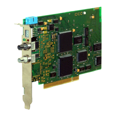
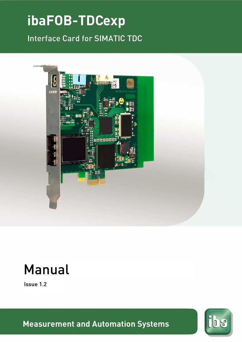
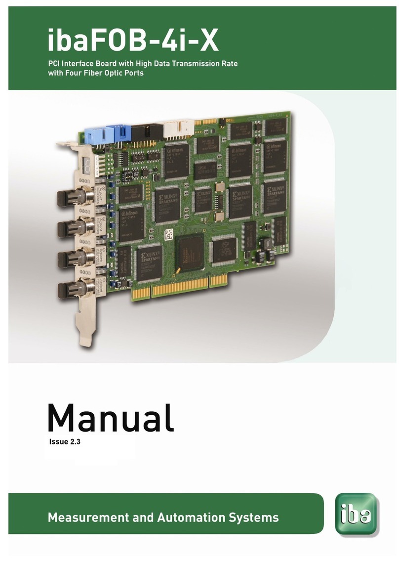
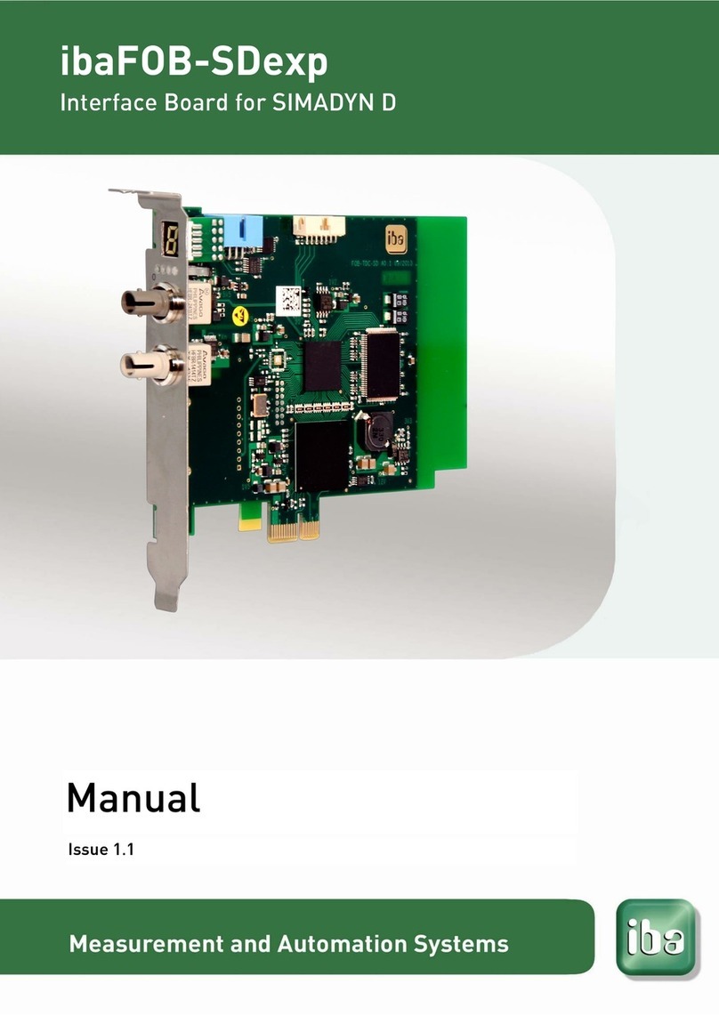
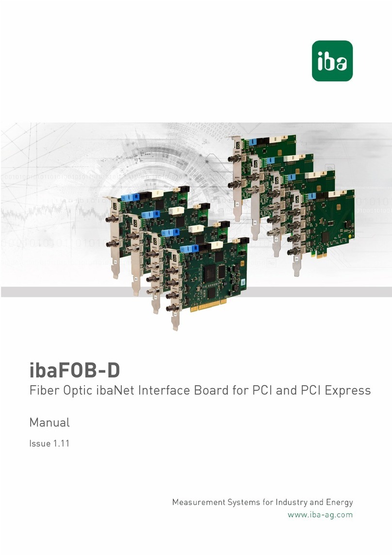
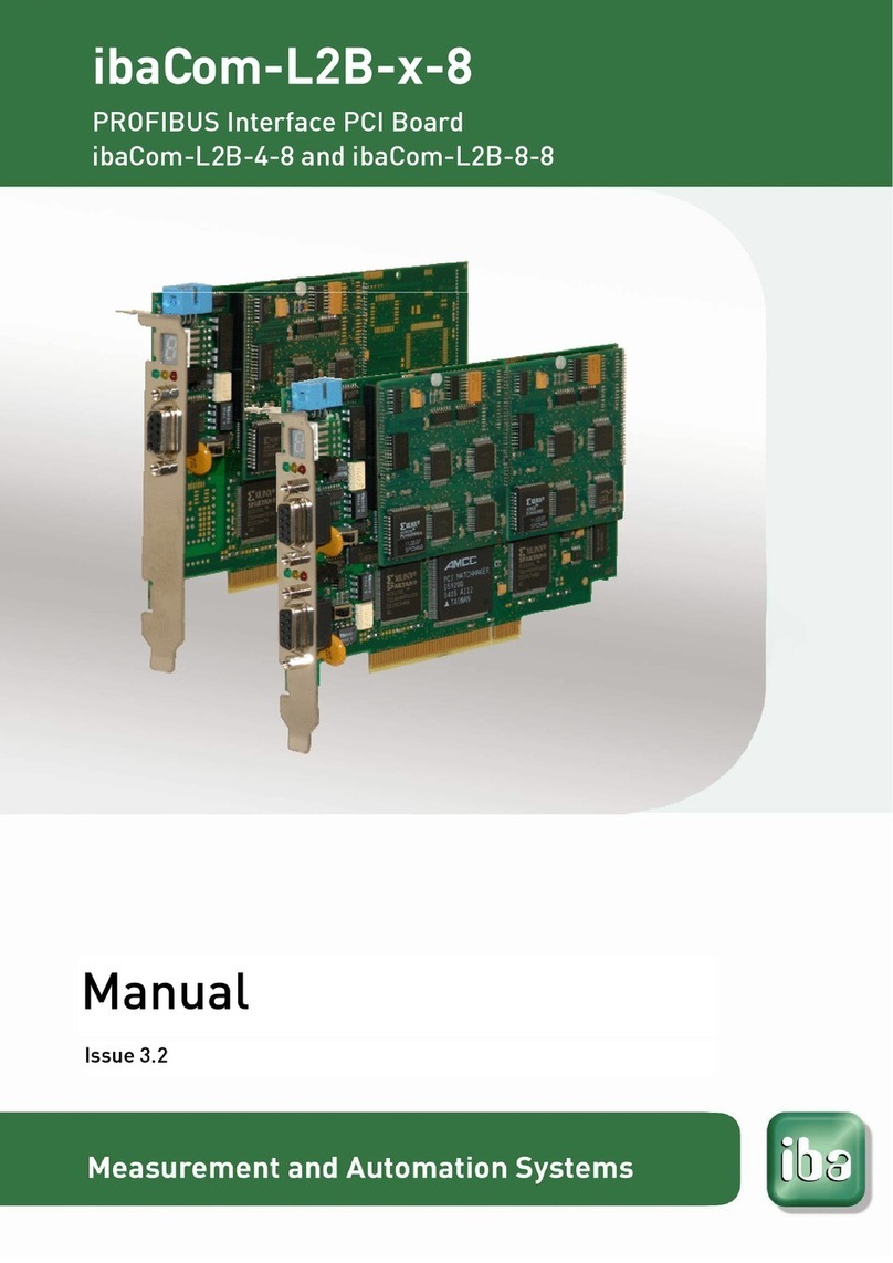
IBA ibaFOB-4i-S User manual

3.1
en
Version 3.2

Page 2 Manual ibaFOB-4i-S / -io-S
ibaFOB-4i-S / -io-S -Manual
Issued by
iba AG
Koenigswarterstr. 44
90762 Fuerth, Germany
Tel.: + 49 (0)911 9 72 82-0
Sales -27
Support -14
R&D -13
FAX -33
Email: [email protected]
Web: www.iba-ag.com
Unless explicitly stated to the contrary, it is not permitted to pass on or copy this docu-
ment, nor to make use of its contents or disclose its contents. Any violation is treated as
an act liable for damages.
iba AG 2009 all rights reserved.
ibaFOB-4i-S / -io-S - Manual V 3.2 en / ibaFOB A2 / A8
We have checked that the contents of this manual match the hardware and software de-
scribed here. However, deviations cannot be fully ruled out, so that we cannot assume
any warranty should any deviations actually exist. This manual is regularly updated. Nec-
essary revisions are included in future editions, or can be downloaded from the Internet.
The latest version is always available for downloading at:
http://www.iba-ag.com
We would welcome any suggestions for improvements which you may have.
Version Date Revision Chapter / pages Author Version HW/FW
V 3.2 03/05/12 Chapter Accessories removed st
iba AG 2012

ibaFOB-4i-S / -io-S Manual Page 3
Contents
This manual 4
1Introduction 5
2Scope of Delivery 7
3Safety Information 7
4Installation / Uninstallation 8
4.1 Preparation.................................................................................... 8
4.2 Installing the Card ......................................................................... 9
4.3 Removing the Card ....................................................................... 9
5System Requirements 10
5.1 Hardware..................................................................................... 10
5.2 Software ...................................................................................... 10
6Driver installation 11
6.1 Windows XP .................................................................................11
7System Integration 13
7.1 Topologies ................................................................................... 13
8Device description 15
8.1 Device properties ........................................................................ 15
8.2 Views, Displays and Connectors ................................................. 16
8.2.1. ibaFOB-io-S ...........................................................................................16
8.2.2. ibaFOB-4i-S ...........................................................................................16
8.3 Front Side Elements.................................................................... 17
8.3.1. LEDs ......................................................................................................17
8.3.2. 7-Segment Display.................................................................................17
8.3.3. Fiber Optic Interface of ibaFOB-io-S......................................................17
8.3.4. Fiber Optic Interfaces of ibaFOB-4i-S....................................................17
8.3.5. Fiber Optic Interfaces of ibaFOB-4o (optional) ......................................18
8.3.6. Fiber Optic Interfaces of ibaFOB-OF-Link (optional)..............................18
8.3.7. Synchronisation Output Module ibaFOB-Sync-Out (optional)................19
8.3.8. Synchronisation Input Module ibaFOB-Sync-In (optional) .....................19
9Configuration and Engineering 20
9.1 Configuration and Diagnostics with ibaPDA-V6........................... 20
9.1.1. Configuration of the Card.......................................................................20
9.1.2. Module and Signal Configuration...........................................................21
9.1.3. Diagnosis ...............................................................................................23
10 Synchronization of Several Boards 24
11 Technical Data 25
12 Support 26
iba AG 2012

Page 4 Manual ibaFOB-4i-S / -io-S
This manual
This compact manual provides the information for installation and handling of the devices
ibaFOB-4i-S / -io-S, ibaFOB-io-S, ibaFOB-4o, ibaFOB-OF-Link and ibaFOB-Sync.
For further information concerning the system integration and software configuration
please refer to the corresponding engineering manuals and / or software documentation
of our software products used in conjunction with this device.
You can find the latest issue of this manual always on our website
http://www.iba-g.com in the download area.
This manual uses several symbols which essentially have the following meanings:
Important hint or warning in order to avoid hazard against material or life.
A useful tip or clue to make your work easier.
This draws your attention to special features, such as exceptions to rules, etc.
A reference to additional documentation or more in-depth literature.
iba training courses
Hint for training courses by iba concerning related products or subjects
Copyright notice
Windows is a registered trademark of Microsoft Corporation.
Other product or company names mentioned in this manual may be brand names or regis-
tered trademarks of the corresponding owner.
iba AG 2012

ibaFOB-4i-S / -io-S Manual Page 5
1Introduction
The boards ibaFOB-io-PCI, ibaFOB-io-S, ibaFOB-4i-PCI, ibaFOB-4i-S, ibaFOB-4o and
ibaFOB-OF-Link are fiber optic communication cards which are used to connect a stan-
dard PC to the iba peripheral devices such as ibaPADUs, ibaNet750-BM devices and
ibaLink signal modules (SM).
As far as the following text does not refer to a particular card, the boards are referred to
as ibaFOB boards.
The unique peripheral I/O concept based on the ibaFOB boards, features characteristics
otherwise unknown on standardized field buses such as:
Full deterministic transmission profiles for all fiber optic buses and connected devices
(1ms).
Internal and/or external synchronization on the bus, even for more than one bus with
programmable cycle times between 1.0 and 9.9 ms in steps of 100 μs.
Deviation less than 2 μs between several busses (external synchronization)
The iba fiber optic transmission standard integrates not only A/D converters (ibaPADU)
but a huge variety of PLC interfaces and hence allows the realization of heterogene-
ous measuring and I/O topologies. The following devices can be connected:
ibaFOB x/4 (ISA)
ibaFOB x/4-F (ISA) with ibaFOB-OF-Link
ibaFOB 2/2 I/O (ISA)
ibaLink-SM-64-io (Siemens Simatic S5 115U, 135U 155U; MMC216 all types)
ibaLink-SM-128V-i-2o (VME32 & VME64 rack)
ibaNet750-BM (Wago IO system 750)
ibaBM-FOX-i-3o (FO-splitter and repeater)
ibaPADU-8, ibaPADU-8-ICP, ibaPADU-8-M, ibaPDAU-8-S, ibaPADU-16, ibaPADU-
32-T, ibaPADU-32-R and ibaPADU-8-O (A/D & D/A -converter)
ibaBM-SLM (Simolink Monitor for Siemens Motion Link Bus)
ibaBM-DDCSM (Monitor for ABB DDCS+ Drivebus)
Adjustable bus timing (ring topology in combination with ibaLogic only!)
Easy handling without the termination problems of copper based systems
The integration in hazardous areas is no problem in terms of EMI due to the fiber
optic communication concept.
One source can be accessed by multiple clients at the same time by just multiply-
ing the optical fibers (ibaFOx-3 and ibaFOB-OF-Link splitting devices) – so I/O pe-
ripherals may be used for process control and measuring at the same time. This
also makes redundant structures easy.
100% compatibility to its predecessors based on the ISA bus
iba AG 2012
Page 6 Manual ibaFOB-4i-S / -io-S
iba AG 2012
The ibaFOB-4i-S or ibaFOB-io-S devices represent the new generation of iba's fiber optic
PC boards. These boards replace the ibaFOB x/4, ibaFOB x/4-F and ibaFOB 2/2 IO
boards which were based on the PC ISA bus definition. The new boards are 100% com-
patible on the fiber optical bus side while in the PC the interface and dual port ram layout
differ between the old and new boards.
The new cards features are:
Full Plug&Play functionality.
Enhanced throughput on the PC bus side.
Enhanced card diagnostics and card information (LEDs and 7-segment display).
Two modes of operation: F-mode and M-mode, to be selected for each FO-port in-
dividually
Optional synchronization modules for synchronizing multiple systems in conjunction
with ibaScope

ibaFOB-4i-S / -io-S Manual Page 7
iba AG 2012
2Scope of Delivery
The following components are included with the delivery.
ibaFOB-4i-S or ibaFOB-io- PCI device (6-wire flat ribbon cable with four jacks for
iba card synchronization)
Manual
3Safety Information
Please consider the following safety advises:
W A R N I N G!
To avoid electrical shock during installation or uninstallation of the device
disconnect the power supply from the computer before opening.
C A U T I O N !
This board contains components which can be destroyed by electrostatic discharge.
Prior to touching any electronics board, your body must be electrically discharged. This
can be simply done by touching a conductive, grounded object immediately beforehand
(e.g. bare metal cabinet components, socket protective conductor contact).

Page 8 Manual ibaFOB-4i-S / -io-S
4Installation / Uninstallation
4.1 Preparation
The card fits in every compatible PCI slot.
C A U T I O N !
Use a ground line or discharge any electrostatic charge from yourself before touching
the card.
The standards for handling electrostatic sensitive devices (ESD) must be followed.
Note
Please follow carefully the advises below. Not to do so may void your warranty.
Remove and install cards only in a ESD designated workspace.
Remove all power connections from the PC before opening the PC and/or install-
ing/removing any device.
Never remove or (un-)solder chips or other parts of the device because this may
damage the device and void your warranty.
iba AG 2012

ibaFOB-4i-S / -io-S Manual Page 9
iba AG 2012
4.2 Installing the Card
1
Switch off the PC, disconnect it from power supply and open it, so that you
can see the PCI slots.
2 Unpack the card carefully. Use a ground line or discharge any electrostatic
charge from yourself before touching the card.
3 No settings of jumpers or switches are required.
4 Take hold of the card on the board edges and the front panel.
5 Press the card carefully into the desired PCI connector of the main board
Check that the card is fully
.
plugged into the slot and fix the card with the
Close the computer, connect the power supply and start it.
4.3
computer, disconnect it from the power supply and
3 Pull out the card off the PCI slot carefully and put in a safe place or conduc-
tive plastic bag.
screw on the front panel.
6
Removing the Card
In order to remove the card from the PC please follow these steps:
1 Stop and switch off the
open it.
2 Release the screw in the front panel.

Page 10 Manual ibaFOB-4i-S / -io-S
iba AG 2012
5System Requirements
5.1 Hardware
IBM-compatible PC with the following minimum configuration:
400 MHz Pentium II or better
At least one free PCI slot
128 MB RAM or better
Please see http://www.iba-ag.com for further details on a properly outfitted workstation.
5.2 Software
Microsoft Windows NT 4.0 (Service Pack 5 or higher), 2000, XP or 2003 Server
ibaPDA Version 4.0 with PCI support or higher, > 10 GB disk space
ibaLogic
ibaScope
ibaQDR

ibaFOB-4i-S / -io-S Manual Page 11
6Driver installation
6.1 Windows XP
The ibaFOB-4i-S and ibaFOB-io-S cards comply with the Plug & Play standard of Win-
dows.
After the card has been plugged in for the first time and after Windows has finished its
startup after booting the Found New Hardware Wizard pops up for introduction to the in-
stallation of the drivers. In case the dialog should not open use the Windows “Add Hard-
ware Wizard” in the control panel in order to look for new hardware..
If the dialog appears select “No, not this time“. Continue with <Next>.
In the next step select the option “Install the software automatically“ and click on <Next>.
iba AG 2012

Page 12 Manual ibaFOB-4i-S / -io-S
iba AG 2012
The system is looking for driver software and installs it automatically. Finally click on <Fin-
ish>.
If you like to check if the card was properly installed open the Windows „Device Manager“
and look for the card under the iba devices node.

ibaFOB-4i-S / -io-S Manual Page 13
7System Integration
7.1 Topologies
The following schematics show how the different boards may be combined to achieve a
full monitored process I/O system for 256 analog and 256 digital in- and outputs.
To do this connect the ibaFOB-4o to the ibaFOB-4i-S (with the 10 pole connector).
The ibaFOB-4o as well as the ibaFOB-4i-S hold the additional connector (6-pole) to wire
the ibaFOB-OF-Link card which monitors the in and outputs without additional time delay.
Parallel (monitored) output signals (max. 256
A + 256 D)
Output signals (max. 256 A + 256 D)
Input signals (max. 256 A + 256 D)
Parallel (monitored) input signals (max. 256 A
+ 256 D)
iba AG 2012

Page 14 Manual ibaFOB-4i-S / -io-S
iba AG 2012
If the PC power supply is switched OFF, all “monitored signals” are off because the
monitoring involves an optical – electrical –optical conversion - which cannot work
without the PC´s power supply.
The ibaFOB-io-S card can only monitor the input signals – not the output signals! If this
feature is needed please use the ibaFOx-3 device.

ibaFOB-4i-S / -io-S Manual Page 15
8Device description
8.1 Device properties
Full compliant PCI V2.2 board
One bi-directional (ibaFOB-io-S) or four unidirectional (ibaFOB-4i-S) independent
fiber optic channels
Expansion connector for ibaFOB-4o to get four bi-directional channels on an iba-
FOB-4i-S.
Each optical link has its own processor with up to 5 Mbit/s
1 MByte of PCI dual port ram for PC access
Firmware upgrade in the PC without deinstalling the card (starts with card version
3)
Three LEDs for each channel indicating CPU life counter (green), optical transmis-
sion status (yellow) and processor error (red)
7-segment display for board-ID, indication of sync master board and external or in-
ternal synchronization.
Expansion connector for FOB-OF-Link to monitor the input data streams on iba-
FOB-4i-S or ibaFOB-io-S.
No jumpers or DIL switches, all parameters are software controlled (the switch on
top of the board is for iba internal use only)
Dynamic reassigning of interrupt sources and interrupt generation (board and driver
synchronization)
Dynamic assignment of bus cycle time in steps of 1μs (accuracy +/-400 ns). Mini-
mum cycle is 1.000 ms; max cycle 9.900 ms; Default 1.000 ms (ring topology only!)
Synchronous sampling on daisy chained devices on the fiber optic bus can differ
with a maximum of -800 ns to + 1300 ns relative to device #1 channels (worst case
measured with 1 ms basic sampling time); the fiber optics between devices should
not exceed 1 m.
iba AG 2012

Page 16 Manual ibaFOB-4i-S / -io-S
8.2 Views, Displays and Connectors
8.2.1. ibaFOB-io-S
iba AG 2012
ibaFOB-OF-Link-connector
Sync-i / Sync-o-connector
Sync-IRQ-connector
7-Segment display
LEDs
Receiver (grey)
Transmitter (white)
8.2.2. ibaFOB-4i-S
ibaFOB-OF-Link- connector
ibaFOB-4o- connector
Sync-i / Sync-o- connector
Sync-IRQ- connector
7-Segment display
LEDs
4 receivers (grey)

ibaFOB-4i-S / -io-S Manual Page 17
8.3 Front Side Elements
8.3.1. LEDs
Run, Link and Error LEDs indicate the operational state of the ibaFOB channels. The fol-
lowing table describes the states in which you may find the LEDs and their respective
meanings. When switching on power all LEDs are on for a few seconds to prove their
proper function.
LED Status Description
Run
(green)
FLASHING
OFF
power is on and the channel is functioning properly
controller stopped
Link (yel-
low)
ON
OFF
receiving / sending telegrams on this channel
no telegrams received; fiber optics not connected or sending device
Error (red) ON
OFF
internal error in controller link
normal state; after resolution of error, LED automatically resets
8.3.2. 7-Segment Display
The 7-segment display shows the following information
Board-ID (ranging from 0...7) - after board was initialized; when board is not initial-
ized a horizontal line is displayed.
The decimal point in the display indicates whether the board is dedicated to be...
an internal interrupt master (dot is on) or
an external interrupt master (dot is blinking) or
an interrupt slave (dot is off).
8.3.3. Fiber Optic Interface of ibaFOB-io-S
The ibaFOB-io-S provides two ST type jacks - one optical sender (white) and one optical
receiver (grey).
If the card was configured for external synchronization, e. g. for operation with an
ibaBM-SLM, the input channel needs to be connected with the external device for
proper function (otherwise the whole PC process will be stopped).
The external sync configuration channel will be indicated by a blinking point in the 7-
segment display so that the correct data input can be identified easily.
8.3.4. Fiber Optic Interfaces of ibaFOB-4i-S
The ibaFOB-4i-S provides four optical receivers (grey ST jacks). Channel 1 is located
nearest to the 7-segment display.
If the card was configured for external synchronization, e. g. for operation with an
ibaBM-SLM, the first (upper) input channel needs to be connected with the external
device for proper function (otherwise the whole PC process will be stopped).
The external sync configuration channel will be indicated by a blinking point in the 7-
segment display so that the correct data input can be identified easily.
iba AG 2012

Page 18 Manual ibaFOB-4i-S / -io-S
8.3.5. Fiber Optic Interfaces of ibaFOB-4o (optional)
The ibaFOB-4o provides four optical transmitters (white ST jacks). Channel #1 is the up-
per channel.
Beside the fiber optic ports, this module provides fur-
ther connections to…
- ibaFOB-4i-S (compatible to all predecessors)
- ibaFOB-OF-Link
Two different builds are available:
a) with short front plate (picture)
ibaRackline PCs have special slots in the housing for
this kind of build. They enable installation of these
modules without blocking regular PCI slots.
b) with long standard front plate
This kind may be installed on all standard slots in any
PC. The opening in the housing will be blocked for
other PC cards though the PCI connector is not used.
8.3.6. Fiber Optic Interfaces of ibaFOB-OF-Link (optional)
The ibaFOB-OF-Link provides four optical senders (white ST jacks)
Channel #1 is the upper channel.
Shown with connector cable to
- ibaFOB-4i-S (incl. all predecessors) or
- ibaFOB-4o-S
Two different builds are available:
a) with short front plate (picture)
ibaRackline PCs have special slots in the housing for
this kind of build. They enable installation of these
modules without blocking regular PCI slots.
b) with long standard front plate
This kind may be installed on all standard slots in any
PC. The opening in the housing will be blocked for
other PC cards though the PCI connector is not used.
iba AG 2012

ibaFOB-4i-S / -io-S Manual Page 19
8.3.7. Synchronisation Output Module ibaFOB-Sync-Out (optional)
When working with ibaScope in distributed configurations it may be required to connect
and synchronize multiple ibaScope acquisition PCs.
We've developed a pair of synchronization modules which use a fiber optic connection to
send and receive a synchronization impulse.
The module ibaFOB-Sync-Out has to be installed in the PC which is supposed to be the
synchronization master.
The synchronization output module is designed for as-
sembly in a short housing slot.
It provides four fiber optic outputs which transmit the
synchronization signal. Hence, up to four other PCs
can be synchronized. If an ibaFOB-OF-Link is con-
nected to the grey connector on the module, the fiber
optic outputs can be doubled and four more PCs may
be synchronized.
The blue jacks on the flat ribbon cable should be
plugged into the light blue connectors on the iba PCI-
cards in the master PC. One card among these must
be configured as interrupt master.
The white jack on the flat ribbon cable should be
plugged into the dark blue Sync-i / Sync-o connector of
an ibaFOB-4i-S or ibaFOB-io-S card for power supply
of the synchronization module.
8.3.8. Synchronisation Input Module ibaFOB-Sync-In (optional)
The module ibaFOB-Sync-In has to be installed in the PC(s) which is (are) supposed to
be the synchronization slave(s). One ibaFOB-Sync-In must be installed in each slave PC.
The synchronization input module is designed for as-
sembly in a short housing slot.
It provides one fiber optic inputs which receives the
synchronization signal.
The blue jacks on the flat ribbon cable should be
plugged into the light blue connectors on the iba PCI-
cards in the slave PC. One card among these (iba-
FOB-4i-S or ibaFOB-io-S)must be configured as inter-
rupt master/external.
The white jack on the flat ribbon cable should be
plugged into the dark blue Sync-i / Sync-o connector
of an ibaFOB-4i-S or ibaFOB-io-S card for power
supply of the synchronization module.
The use of this synchronization function is supported by ibaScope only.
iba AG 2012

Page 20 Manual ibaFOB-4i-S / -io-S
9Configuration and Engineering
9.1 Configuration and Diagnostics with ibaPDA-V6
You will find a detailed description of the configuration parameters for the card in
ibaPDA-V6 in the manual and/or in the online help of ibaPDA-V6..
The entire configuration is to be done in the I/O-manager of ibaPDA-V6. The board is
managed as data interface of type FOBF-PCI.
The same interface type is used for ibaFOB-4i-S and ibaFOB-io-S. The system automati-
cally detects which type(s) of card(s) are installed in the PC and displays them in the sig-
nal tree
9.1.1. Configuration of the Card
If you mark the branches in the tree view you'll get the relevant information and you can
make the required settings respectively.
A mimic of the card is displayed in the dialog box when you mark the main branch of the
card in the tree view.
At this point you should set the interrupt mode (master internal / master external / slave).
If you mark the sub branches with the links you'll get further information about the proc-
essors.
iba AG 2012
Table of contents
Other IBA Computer Hardware manuals

IBA
IBA ibaW-750 User manual

IBA
IBA ibaPADU-S-IT-2x16 User manual

IBA
IBA ibaLink-VME User manual

IBA
IBA Com-L2B-4-8 User manual

IBA
IBA ibaFOB-PlusControl User manual

IBA
IBA ibaFOB-TDCexp User manual

IBA
IBA ibaFOB-D User manual

IBA
IBA FOB-SDexp User manual

IBA
IBA FOB-SD User manual

IBA
IBA ibaPADU-S-IT-16 User manual