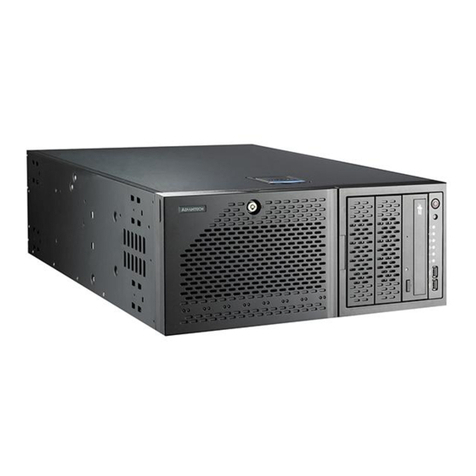
IBM 3455-D3E User manual

© Copyright IBM Corporation 2019, 2020, 2021 Customer Install Guide, 1U Chassis 1
IBM Cloud Pak for Data system
Customer Install Guide
Chassis
3455-D3E
Version 1.4
Note
Before using this information and the product it supports, read the information in
“Safety notices” on page 5, “Notices” on page 39, the IBM Systems Safety Notices
manual, G229-9054, and the IBM Environmental Notices and User Guide.

© Copyright IBM Corporation 2019, 2020, 2021 Customer Install Guide, 1U Chassis 2
This edition applies to IBM Cloud Pak for Data System Components.
Revised November 2021
© Copyright IBM Corporation 2019, 2020, 2021
US Government Users Restricted Rights –Use, duplication or disclosure restricted by
GSA ADP Schedule Contract with IBM Corp.

© Copyright IBM Corporation 2019, 2020, 2021 Customer Install Guide, 1U Chassis 3
Contents
Safety..............................................................................................................................4
Safety Notices.................................................................................................................5
Publications...................................................................................................................14
Cloud Pak for Data System 1U chassis description ......................................................15
Cloud Pak for Data System 1U chassis hardware specifications..................................17
3455-D3E, Cloud Pak for Data System 1U server chassis ........................................17
Operating Environment .................................................................................................18
Rack Requirements.......................................................................................................19
Rack Space................................................................................................................19
Location in the Rack......................................................................................................20
Package Contents.........................................................................................................23
Chassis Installation Procedure......................................................................................24
Rack rail parts inventory ............................................................................................24
Install slide rails into the rack.....................................................................................25
Install the enclosure on the slide rails........................................................................27
Slide the enclosure into the rack................................................................................28
Install the cable management arm.............................................................................28
Electronic Emissions Notices........................................................................................33
Regulatory and Compliance..........................................................................................38
Notices..........................................................................................................................39
Copyright License:.........................................................................................................42
Trademarks...................................................................................................................43
Readers’ Comments......................................................................................................44

© Copyright IBM Corporation 2019, 2020, 2021 Customer Install Guide, 1U Chassis 4
Safety
Before installing this product, read the Safety Information.
Antes de instalar este produto, leia as Informações de Segurança.
Læs sikkerhedsforskrifterne, før du installerer dette produkt.
Lees voordat u dit product installeert eerst de veiligheidsvoorschriften.
Ennen kuin asennat tämän tuotteen, lue turvaohjeet kohdasta Safety Information.
Avant d'installer ce produit, lisez les consignes de sécurité.
Vor der Installation dieses Produkts die Sicherheitshinweise lesen.
Prima di installare questo prodotto, leggere le Informazioni sulla Sicurezza.

© Copyright IBM Corporation 2019, 2020, 2021 Customer Install Guide, 1U Chassis 5
Les sikkerhetsinformasjonen (Safety Information) før du installerer dette produktet.
Antes de instalar este produto, leia as Informações sobre Segurança.
Antes de instalar este producto, lea la información de seguridad.
Läs säkerhetsinformationen innan du installerar den här produkten
Safety Notices
These statements provide the caution and danger information used in this
documentation.
Important:
Each caution and danger statement in this documentation is labeled with a number.
This number is used to cross reference an English-language caution or danger
statement with translated versions of the caution or danger statement in the Safety
Notices Translation document (PN G229-9054).
For example, if a caution statement is labeled "D005," translations for that caution
statement are in the Safety Notices Translation document under "D005."
Be sure to read all caution and danger statements in this documentation before you
perform the procedures. Read any additional safety information that comes with your
system or optional device before you install the device.
D005
DANGER: When working on or around the system, observe the following precautions:

© Copyright IBM Corporation 2019, 2020, 2021 Customer Install Guide, 1U Chassis 6
Electrical voltage and current from power, telephone, and communication cables are
hazardous. To avoid a shock hazard:
If IBM supplied the power cord(s), connect power to this unit only with the IBM provided
power cord. Do not use the IBM provided power cord for any other product.
Do not open or service any power supply assembly.
Do not connect or disconnect any cables or perform installation, maintenance, or
reconfiguration of this product during an electrical storm.
The product might be equipped with multiple power cords. To remove all hazardous
voltages, disconnect all power cords.
For AC power, disconnect all power cords from their AC power source.
For racks with a DC power distribution panel (PDP), disconnect the customer’s DC
power source to the PDP.
When connecting power to the product ensure all power cables are properly connected.
For racks with AC power, connect all power cords to a properly wired and grounded
electrical outlet. Ensure that the outlet supplies proper voltage and phase rotation
according to the system rating plate.
For racks with a DC power distribution panel (PDP), connect the customer’s DC power
source to the PDP. Ensure that the proper polarity is used when attaching the DC power
and DC power return wiring.
Connect any equipment that will be attached to this product to properly wired outlets.
When possible, use one hand only to connect or disconnect signal cables.
Never turn on any equipment when there is evidence of fire, water, or structural
damage.
Do not attempt to switch on power to the machine until all possible unsafe conditions
are corrected.
Assume that an electrical safety hazard is present. Perform all continuity, grounding,
and power checks specified during the subsystem installation procedures to ensure that
the machine meets safety requirements.
Do not continue with the inspection if any unsafe conditions are present.
Before you open the device covers, unless instructed otherwise in the installation and
configuration procedures: Disconnect the attached AC power cords, turn off the
applicable circuit breakers located in the rack power distribution panel (PDP), and
disconnect any telecommunications systems, networks, and modems.

© Copyright IBM Corporation 2019, 2020, 2021 Customer Install Guide, 1U Chassis 7
DANGER:
Connect and disconnect cables as described in the following procedures when
installing, moving, or opening covers on this product or attached devices.
To Disconnect:
Turn off everything (unless instructed otherwise).
For AC power, remove the power cords from the outlets.
For racks with a DC power distribution panel (PDP), turn off the circuit breakers located
in the PDP and remove the power from the Customer's DC power source.
Remove the signal cables from the connectors.
Remove all cables from the devices.
To connect:
Turn off everything (unless instructed otherwise).
Attach all cables to the devices.
Attach the signal cables to the connectors.
For AC power, attach the power cords to the outlets.
For racks with a DC power distribution panel (PDP), restore the power from the
Customer's DC power source and turn on the circuit breakers located in the PDP.
Turn on the devices.
Sharp edges, corners and joints may be present in and around the system. Use care
when handling equipment to avoid cuts, scrapes and pinching. (D005)
C002
CAUTION: Only trained service personnel may replace this battery. The battery
contains lithium. To avoid possible explosion, do not burn or charge the battery.

© Copyright IBM Corporation 2019, 2020, 2021 Customer Install Guide, 1U Chassis 8
Do not:
Throw or immerse into water
Heat to more than 100°C (212°F)
Repair or disassemble
Exchange only with the approved part. Recycle or discard the battery as instructed by
local regulations. (C002)
C026
CAUTION: This product might contain one or more of the following devices: CD-ROM
drive, DVDROM drive, DVD-RAM drive, or laser module, which are Class 1 laser
products. Note the following information:
Do not remove the covers. Removing the covers of the laser product could result in
exposure to hazardous laser radiation. There are no serviceable parts inside the device.
Use of the controls or adjustments or performance of procedures other than those
specified herein might result in hazardous radiation exposure.
(C026)
IBM® servers can use I/O cards or features that are fiber-optic based and that utilize
lasers or LEDs.
Laser compliance
IBM servers may be installed inside or outside of an IT equipment rack.
All lasers are certified in the U.S. to conform to the requirements of DHHS 21 CFR
Subchapter J for class 1 laser products. Outside the U.S., they are certified to be in
compliance with IEC 60825 as a class 1 laser product. Consult the label on each part
for laser certification numbers and approval information.
CAUTION:
Data processing environments can contain equipment transmitting on system links with
laser modules that operate at greater than Class 1 power levels. For this reason, never

© Copyright IBM Corporation 2019, 2020, 2021 Customer Install Guide, 1U Chassis 9
look into the end of an optical fiber cable or open receptacle. Although shining light into
one end and looking into the other end of a disconnected optical fiber to verify the
continuity of optic fibers many not injure the eye, this procedure is potentially
dangerous. Therefore, verifying the continuity of optical fibers by shining light into one
end and looking at the other end is not recommended. To verify continuity of a fiber
optic cable, use an optical light source and power meter. (C027)
CAUTION:
This product contains a Class 1M laser. Do not view directly with optical instruments.
(C028)
CAUTION:
Some laser products contain an embedded Class 3A or Class 3B laser diode. Note the
following information: laser radiation when open. Do not stare into the beam, do not
view directly with optical instruments, and avoid direct exposure to the beam. (C030)
CAUTION: To reduce the risk of electric shock or energy hazards:
This equipment must be installed by trained service personnel in a restricted-access
location, as defined by the NEC, IEC 60950 and IEC 62368, The Standard for Safety of
Information Technology Equipment.
(R001 part 1)
DANGER: Observe the following precautions when working on or around your IT rack
system:
Heavy equipment–personal injury or equipment damage might result if mishandled.
Always lower the leveling pads on the rack cabinet.

© Copyright IBM Corporation 2019, 2020, 2021 Customer Install Guide, 1U Chassis 10
Always install stabilizer brackets on the rack cabinet unless the earthquake option is to
be installed.
To avoid hazardous conditions due to uneven mechanical loading, always install the
heaviest devices in the bottom of the rack cabinet. Always install servers and optional
devices starting from the bottom of the rack cabinet.
Rack-mounted devices are not to be used as shelves or work spaces. Do not place
objects on top of rack-mounted devices. In addition, do not lean on rack mounted
devices and do not use them to stabilize your body position (for example, when working
from a ladder).
Each rack cabinet might have more than one power cord.
For AC powered racks, be sure to disconnect all power cords in the rack cabinet when
directed to disconnect power during servicing.
For racks with a DC power distribution panel (PDP), turn off the circuit breaker that
controls the power to the system unit(s), or disconnect the customer’s DC power
source, when directed to disconnect power during servicing.
Connect all devices installed in a rack cabinet to power devices installed in the same
rack cabinet. Do not plug a power cord from a device installed in one rack cabinet into a
power device installed in a different rack cabinet.
An electrical outlet that is not correctly wired could place hazardous voltage on the
metal parts of the system or the devices that attach to the system. It is the responsibility
of the customer to ensure that the outlet is correctly wired and grounded to prevent an
electrical shock. (R001 part 1)
R007
CAUTION: Use safe practices when lifting.
L001

© Copyright IBM Corporation 2019, 2020, 2021 Customer Install Guide, 1U Chassis 11
DANGER: Hazardous voltage, current, or energy levels are present inside any
component that has this label attached. Do not open any cover or barrier that contains
this label. (L001)
L002
DANGER: Rack-mounted devices are not to be used as shelves or work spaces. Do not
place objects on top of rack-mounted devices. In addition, do not lean on rack-mounted
devices and do not use them to stabilize your body position (for example, when working
from a ladder). (L002)

© Copyright IBM Corporation 2019, 2020, 2021 Customer Install Guide, 1U Chassis 12
(L003)
or or

© Copyright IBM Corporation 2019, 2020, 2021 Customer Install Guide, 1U Chassis 13
or or
DANGER: Multiple power cords. The product might be equipped with multiple AC power
cords or multiple DC power cables. To remove all hazardous voltages, disconnect all
power cords and power cables. (L003)
Product Safety Notifications, Japan
(English translation: If this product comes with power cords, such cords should
be used exclusively for the applicable product, but not for other devices.)
(English translation: After providing the main product, if additional power cord is
required, the cord is handled for repair/maintenance/mending purpose.)

© Copyright IBM Corporation 2019, 2020, 2021 Customer Install Guide, 1U Chassis 14
Publications
The following IBM documentation is available on the Safety and Regulatory CD included
with your Cloud Pak for Data System rack & components:
**** General Information Guides ****
•Rack Safety Information
•IBM Enterprise Slim Rack Safety Instructions
•IBM Safety Labels
•Unpacking Instructions
•Acoustical Caution Statement
•Environmental Notices and User Guide
•Important Notices
•IBM Systems Safety Notices translations Pub
**** Rack Install Guides ****
•Customer Install Guide, Rack and System 3458, 3459 (Appliance Racks)
•Customer Install Guide, Rack and System 3454-GEF, 3454-GEH, 3457-GEH
(Component Racks)
**** Component Specific Install Guides ****
•Customer Install Guide, 100G Switch 3454-CAC
•Customer Install Guide, 2U Chassis 3453-C2E
•Customer Install Guide, 1G Switch 3454-A3C
•Customer Install Guide, 25G Switch 3454-B8C 3454-C8C
•Customer Install Guide, Power Distribution Unit (PDU) 3454-FCE, FCG
•Customer Install Guide, 1U Chassis 3455-D3E (this document)
•Customer Install Guide, Connector Node 3453-F7E
**** Wiring Diagrams ****
•3454-GEF,GEH_3457-GEH Recommended Component Rack Power
Connections
•3458-3459 Appliance Rack Power Connections (Appliance racks ONLY)
These documents contain important safety and environmental information along with
specific installation instructions and specifications for the Cloud Pak for Data System
building blocks.
Specific part numbers for these documents are in the readme.txt file on the
included Safety and Regulatory CD.

© Copyright IBM Corporation 2019, 2020, 2021 Customer Install Guide, 1U Chassis 15
Cloud Pak for Data System 1U chassis
description
The IBM Cloud Pak for Data Systems, 1U chassis is a Dell based, server platform with
integrated storage, processing and I/O. The chassis comes as a pretested building
block loaded with software. The base system utilizes four chassis, but expansion
chassis can be included with the initial deployment or at a later date.
The chassis is can be installed in an IBM Cloud Pak rack or a customer supplied rack
meeting the guidelines in the Customer Install Guide, Rack and System document
included on the Safety and Regulatory CD shipped with your Cloud Pak for Data
System components. Additional details can be found in the Site Prep Guide at the IBM
Cloud Pak for Data System site.
The chassis includes multiple cold air inlets used to draw in cold air from the front of the
rack. DO NOT BLOCK ANY INLET OR EXHAUST DUCTS, VENTS OR PORTS.
Blocked cooling access will adversely affect the performance of your Cloud Pak
for Data System and may void your warranty.
Power can be supplied by the available IBM Cloud Pak for Data System PDUs and line
cords or by customer supplied PDUs meeting the power requirements of the Cloud Pak
for Data System components.
If this is a customer install, IBM installation services will wire and power the system
once all racks, power and components are in place.
The front panel of the chassis provides the following components:
1 Left control panel. Contains the system health and system ID, status LED, and
the iDRAC Quick Sync 2 (wireless) indicator.
2 Drive slots. Contains Solid State Drives for Operating System and Storage
3 VGA port. Enables you to connect a display device to the system.
4 Right control panel. Contains the power button, USB port, iDRAC Direct micro
port, and the iDRAC Direct status LED.
5 Information tag

© Copyright IBM Corporation 2019, 2020, 2021 Customer Install Guide, 1U Chassis 16
Figure 1: Front View
The rear panel of the chassis provides the following components:
1 PCIe expansion card slot (2). Used for fabric interconnects.
2 Power supply unit (2)
3 NIC port (4). The NIC ports that are integrated on the network daughter card
(NDC) provide network connectivity.
4. USB 3.0 port (2). The USB ports are 9-pin and 3.0-compliant. These ports
enable you to connect USB devices to the system.
5 VGA port. Enables you to connect a display device to the system.
6 Serial port. Enables you to connect a serial device to the system.
7 iDRAC9 dedicated network port. Use the iDRAC9 dedicated network port to
securely access the embedded iDRAC on a separate management network.
8 System status indicator cable port. Enables you to connect the status indicator
cable and view system status when the CMA is installed.
9 System identification button. The System Identification (ID) button is available on
the front and back of the systems.
Figure 2: Rear View

© Copyright IBM Corporation 2019, 2020, 2021 Customer Install Guide, 1U Chassis 17
Cloud Pak for Data System 1U chassis
hardware specifications
Hardware specifications below provide information for the Cloud Pak for Data System
1U chassis, including dimensions, electrical power and cooling. .
All component installation documents are available on the Safety and Regulatory CD
that comes with your Cloud Pak for Data System components.
3455-D3E, Cloud Pak for Data System 1U server chassis [see Notes 1, 2, 3]
Table 1
Width
Depth
Height
EIA
units
Weight
Amperage
(Max)
Power
(Max)
Cooling
(Max)
482 mm
(19.0 in)
809 mm
(31.9 in)
43 mm
(1.70 in)
1
21.9 kg
(48.3.lb)
5.5 amps
1100
watts
3750
BTU/Hr
Notes:
[1] The power supplies automatically accept any voltage within the 200-240 V AC,
50/60 Hz rated-voltage range. If dual power supplies are installed and operating, the
power supplies draw approximately equal current from the utility (electrical supply) and
provide approximately equal current to the load.
[2] Power draw and heat load vary greatly by configuration and work load. When you
plan for an electrical system, it is important to use the maximum values but actual power
and cooling will be less.

© Copyright IBM Corporation 2019, 2020, 2021 Customer Install Guide, 1U Chassis 18
Operating Environment
Cloud Pak for Data System components are designed to work together as a system in
an ASHRAE A2 environment. .
Table 2: Operating Environment
Environment
Recommended
operating
Allowable
operating
Nonoperating
ASHRAE
A2
Airflow Direction
Front-to-back
Temperature
18C –27C (61F -
80F)
10C –35C (50F-
95F) [1, 5]
5C –45C (41F –
113F)
Humidity
25% - 60%
noncondensing [2,
4]
20% - 80%
noncondensing [2,
4]
8% - 85% [4]
Maximum
Operating Altitude
3050m (10,000 ft)
[1]
Shipping
Temperature
-40C –60C (-40F –
140F) [3, 4]
Shipping relative
humidity
8% - 90% [4]
[1] Derate maximum allowable dry-bulb temperature by 1C (1.8F) per 300m (984 ft)
increase in altitude above 950m (2,953 ft)
[2] Maximum dewpoint 21°C (70°F)
[3] Short term temperature only for servers with SSDs
[4] Unit must acclimate to data center environment before unboxing to prevent
condensation.
[5] PDUs do not have fresh air cooling and can function in 60C (140F) environments

© Copyright IBM Corporation 2019, 2020, 2021 Customer Install Guide, 1U Chassis 19
Rack Requirements
This section provides information on the space requirements for the rack which will
house the Cloud Pak for Data System Components.
Rack Space
Ensure that the rack in which you plan to install the system meets the space
requirements outlined in the following figure:
Figure 3: Top down view of installed chassis with 4-point horizontal mounting

© Copyright IBM Corporation 2019, 2020, 2021 Customer Install Guide, 1U Chassis 20
Location in the Rack
The base IBM Cloud Pak for Data System consists of four main components (1G
switch, 25G switch, four compute chassis) that are designed to be integrated in the
same rack with PDUs. The recommended component placement is shown in the figure
below. Other configurations can be used if IBM Safety Notices translations Pub # G229-
9054 rules are followed, and the lengths of the supplied cables are not exceeded. The
Cloud Pak for Data System requires all IBM supplied and serviceable components
to be installed below the 42U height. Components on slides, such as server
chassis and connector nodes, must be located at or below U26.
Figure 4. Front view of installed base Cloud Pak component locations.
Labeled “MGT1A”
Labeled “FAB1A”
Labeled “4”
Labeled “3”
Labeled “2”
Labeled “1”
Table of contents
Other IBM Chassis manuals