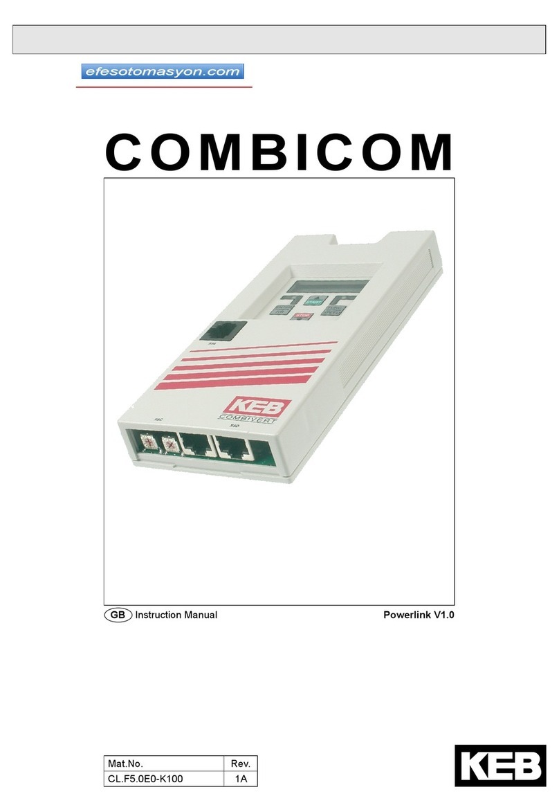
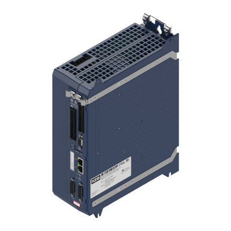
KEBCO COMBIVERT F5 User manual

COMBIVERT
Original manual
Mat.No. Rev.
00F5NES-K000 1F
GB Installation Manual F5 with Safety Function
Control Circuit

History of changes:
Revision Date Description
Rev.1D 2011-02 First published version
Rev.1E 2011-08 Correction: Assignment of terminal strip X2A; Resolution: 11 Bit + sign
Rev.1F 2012-01 Insert certication no.; correcting typing error at chapter 3.3.6 in german

GB - 3
Table of Contents
1. Preface..............................................................................................................5
1.1 General ................................................................................................................................. 5
1.2 Validity and liability ............................................................................................................. 5
1.3 Copyright.............................................................................................................................. 6
1.4 Speciedapplication........................................................................................................... 6
1.5 Product description............................................................................................................. 6
2. Control..............................................................................................................8
2.1 Features of the control........................................................................................................ 8
2.2 Overview .............................................................................................................................. 8
2.2.1 LED1...................................................................................................................................... 9
2.2.2 HSP5 interface X4A............................................................................................................... 9
2.2.3 Encoder interfaces X3A, X3B ................................................................................................ 9
2.2.4 Operators............................................................................................................................... 9
2.2.5 Control terminal strip X2A...................................................................................................... 9
2.2.6 Safety terminal block X2B...................................................................................................... 9
2.3 Connection of the control ................................................................................................. 10
2.3.1 Assembly of the wires.......................................................................................................... 10
2.4 Assignment of the terminal strip X2A...............................................................................11
2.4.1 Connection of the digital inputs............................................................................................ 12
2.4.2 Connection of the digital outputs ......................................................................................... 13
2.4.3 Connection of the analog inputs .......................................................................................... 14
2.4.4 Connection of the analog outputs ........................................................................................ 14
2.4.5 Connection of the relay outputs ........................................................................................... 15
2.5 Assignment of the terminal block X2B ............................................................................ 15
2.5.1 Inputs ................................................................................................................................... 16
2.5.1.1 Specication of the STO inputs ........................................................................................... 16
2.5.1.2 STO with OSSD signals....................................................................................................... 16
2.5.2 Output STO.......................................................................................................................... 16
3. Safety Function STO .....................................................................................17
3.1 Emergency stop according EN 60204 .............................................................................. 18
3.2 ClassicationofSTOaccordingIEC61508 ..................................................................... 19
3.3 ClassicationofSTOaccordingENISO13849 ............................................................... 19
3.4 Additional instructions...................................................................................................... 19
3.5 Functional Description...................................................................................................... 19
3.6 Wiring Examples................................................................................................................ 21
3.6.1 Direct switching off with emergency stop switch.................................................................. 21
3.6.2 Direct switching off with emergency stop switch and monitoring of the wiring .................... 22
3.6.3 Direct switching off by safety module with test pulses......................................................... 23
3.6.4 Wiring SS1........................................................................................................................... 24
4. Certication....................................................................................................25
4.1 Annex to the Declaration of Conformity.......................................................................... 25

GB - 4
Table of Contents

GB - 5
Preface
1. Preface
1.1 General
First we would like to welcome you as a customer of the company Karl E. Brinkmann GmbH
and congratulation to the purchase of this product. You have decided for a product on highest
technical level.
The described hard- and software are developments of the Karl E. Brinkmann GmbH. The
enclosed documents correspond to conditions valid at printing. Misprint, mistakes and tech-
nical changes reserved.
The instruction manual must be made available to the user. Before working with the unit the
user must become familiar with it. This especially applies to the knowledge and observance
of the following safety and warning indications. The used pictograms have following signi-
cance:
Danger Is used, if life or health of the user are endangered or subs-
tantial damage to property can occur.
Warning
Caution
Attention Is used, if a measure is necessary for safe and trouble-free
operation.
observe at
all costs
Information Is used, if a measure simplies the handling or operation of
the unit.
Aide
Tip
Non-observance of the safety instructions leads to the loss of any liability claims. This list is
not exhaustive.
1.2 Validity and liability
The use of our units in the target products is outside of our control and therefore lies
exclusively in the area of responsibility of the machine manufacturer.
The information contained in the technical documentation, as well as any user-specic advice
in spoken and written and through tests, are made to best of our knowledge and information
about the application. However, they are considered for information only without responsibili-
ty. This also applies to any violation of industrial property rights of a third-party.
Selection of our units in view of their suitability for the intended use must be done generally
by the user.
Tests can only be done within the application by the machine manufacturer. They must be
repeated, even if only parts of hardware, software or the unit adjustment are modied.
Unauthorised opening and tampering may lead to bodily injury and property damage and
may entail the loss of warranty rights. Original spare parts and authorized accessories by the
manufacturer serve as security. The use of other parts excludes liability for the consequences
arising out of.
The suspension of liability is especially valid also for operation interruption loss, loss of prot,
data loss or other damages. This is also valid, if we referred rst to the possibility of such
damages.

GB - 6
Preface
If single regulations should be or become void, invalid or impracticable, the effectivity of all
other regulations or agreements is not affected.
1.3 Copyright
The customer may use the instruction manual as well as further documents or parts from it for
internal purposes. Copyrights are with KEB and remain valid in its entirety.
1.4 Speciedapplication
The COMBIVERT F5 serves exclusively for the control and regulation of three-phase motors.
The operation of other electric consumers is prohibited and can lead to the destruction of the
unit. Frequency inverter are components which are intended for the installation in electric
systems or machines.
The used semiconductors and components of KEB are developed and dimensioned for the
use in industrial products. If the KEB COMBIVERT F5 is used in machines, which work under
exceptional conditions or if essential functions, life-supporting measures or an extraordinary
safety step must be fullled, the necessary reliability and security must be ensured by the ma-
chine builder. The operation of our products outside the indicated limit values of the technical
data leads to the loss of any liability claims. The safety function is limited to a service life of
20 years. After this time the unit must be replaced.
1.5 Product description
The product family COMBIVERT F5 with safety function STO has been developed for the
use in safety-oriented applications. The basic standards as well as application and country-
specic standards must be observed furthermore. The standards referred in this manual must
be observed supplementary. Safety function STO according to IEC 61800-5-2 contains:
• Safe torque off (Safe Torque Off - STO)
The safety function meet the requirements in accordance with performance level e (ISO13849-
1) and SIL 3 (IEC 61508 and IEC 62061). In case of proper project design, installation and
operation the safety function protects people against mechanical damages.
This accompanying instruction manual contains information for the installation
and connection of the control of the KEB COMBIVERT F5, as well as the safety
technology.
This instruction manual is only valid in connection with the instruction manual
of the power circuit. This manual contains the general safety requirements and
EMC conform installation.

GB - 7
Preface
COMBIVERT F5 inverter with integrated safety technology have following key numbers:
Control HW used Inverter Control SW Operating mode
(ud.02)
1KF5x30-0009
2KF5x30-0008
up to housing size E
from housing size G
xxF5Kxx-xxxx
APPLICATION
with
encoder inter-
face
MULTI
xxF5Kxx-xx0x
APPLICATION
without
encoder inter-
face
GENERAL
xxF5Lxx-xxxx ASCL MULTI
xxF5Pxx-xxxx SCL SERVO

GB - 8
Control
2. Control
2.1 Features of the control
The control provides the following analog and digital functions:
• Hardware allocation of digital and analog inputs and outputs.
• HSP5 interface for the connection with an operator or via special cable (00F50C0-0010)
with a PC
• Hardware of the control circuit „safety separated“ according to EN 61800-5-1 (base TN-
C/-S mains)
•Operation and diagnosis via operator
• Safety function STO (two channel torque off)
2.2 Overview
Control 2KF5xxx-xxxx from G housing Control 1KF5xxx-xxxx in D & E housing
X6C X6D
X4A
X3B
LED1
X3A
X2B X2A
X6B
LED1
X2A
X2B
X3B
X4A
X6C X6D
X3A
X6B
X2A Control terminal strip X6B HSP5 diagnostic interface
X2B Terminal block safety function X6C
depending on the operator
X3A Encoder interface channel 1 (opti-
on)
X6D
X3B Encoder interface channel 2 (opti-
on)
LED1 Inverter status
X4A HSP5 interface

GB - 9
Control
2.2.1 LED1
The COMBIVERT F5 can be ordered without operator for applications when locally operation
is not required. A status LED for the display of the inverter status is used for the variant wit-
hout operator.
LED status Function
off Unit switched off
on Unit ready for operation
ashing Unit in malfunction
2.2.2 HSP5 interface X4A
The HSP5 interface X4A serves for the communication with a control operator. A digital ope-
rator, interface operator and different eldbus operators are available for this. In order to
avoid malfunctions, the inverter must be brought into noP status before plug on / plug off the
operator (open control release). At start-up the inverter is always started with the last stored
values or factory setting.
A special HSP5 cable (part number 00.F5.0C0-0010) is required for the operation of the KEB
COMBIVERT without operator. This cable is connected between HSP5 interface X4A and
serial RS232 PC interface (COM1 or COM2). The operation occurs via COMBIVIS.
The HSP5 service cable has an integrated level converter. The connection of a serial
standard cable would destroy the PC interface.
2.2.3 Encoder interfaces X3A, X3B
The COMBIVERT F5 can be equipped optionally with encoder interfaces. Different combi-
nations can be used here according to the requirements. The instruction is made separately
according to the installed encoder interfaces.
2.2.4 Operators
The COMBIVERT F5 can be equipped optionally with operator. Different control or eld bus
operators are available here according to the requirements. The instruction is made separa-
tely according to the installed operator.
2.2.5 Control terminal strip X2A
The control terminal block X2A is designed as double, plug-in terminal block with spring cage
connection. It contains 32 pole.
2.2.6 Safety terminal block X2B
The safety terminal block X2A is designed as double, plug-in terminal block with spring cage
connection. It contains 10 pole.

GB - 10
Control
2.3 Connection of the control
The following instructions must be observed at connection:
Attention Prevent EMC malfunctions
•Use shielded / drilled cables
•Lay shield on one side of the inverter onto earth potential
• Lay control and power cable separately (about 10...20 cm apart); Lay
crossings in a right angle (in case it cannot be prevented)
• To avoid interferences a separate shielding must be provided for analog
and digital control lines. Depending on the use of the relay outputs, an ex-
tra shielding is to be used, too.
• In case of inductive load on the relay outputs a protective wiring must be
provided (e.g. free-wheeling diode)!
The terminals of the control terminal strip and the transmitter inputs are secu-
rely isolated in accordance with EN 50178.
2.3.1 Assembly of the wires
Required tools:
Screw driver SD 0.4 x 2.5 (DIN 5264)
1. Strip the line about 7 mm
Stranded wire permissible cross-section
rigidly and exibly 0.08…1 mm2 (AWG22…18)
7mm
2. Plug screw driver mid into the square slot
3. Plug stranded wire into the round slot, that no wires can be
seen from the outside.
4. Remove screw driver and check if the line is xed. Make
sure that the stranded wire and not the insulation is clam-
ped.

GB - 11
Control
2.4 Assignment of the terminal strip X2A
2468 10 12 14 16 18 20 22 24 26 28 30 32
1357911 13 15 17 19 21 23 25 27 29 31
PIN Name Description Specications
10V Digital mass; reference potential for digital inputs/outputs, Uin and Uout
2 Uin Input external voltage supply U=24 VDC +20 %/-15 %
Imax=400 mA
3 0V like pin 1
4 Uout Voltage output for the control of the digital inputs U=24 VDC ±25 %
Imax (Pin 4+32)=100 mA
5RST
Programmable
digital inputs
(Assignment ex factory
see chapter 2.4.1)
8 digital inputs according to IEC61131-2 type 1
„0“ = -3…5 VDC
„1“ = 15…30 VDC
Scan time ≤ 1 ms
6 ST
7 R
8 F
9 I2
10 I1
11 I4
12 I3
13 O2 Programmable
digital outputs
(Assignment ex factory
see chapter 2.4.2)
2 short-circuit proof digital 24 V outputs
specied according to IEC61131-2
Imax = 100mA per output
Switching of inductive load (without free-wheeling
path) up to 300mJ
maximum switching frequency = 1kHz
14 O1
15 0V like pin 1
16 CRF Reference voltage for
setpoint potentiometer 10 VDC +5 %; Imax = 4 mA
17 AN1- Programmable
analog inputs
(Assignment ex factory
see chapter 2.4.3)
0…±10 Vdc (Ri=55 kΩ)
0…±20 mA (Ri=250 Ω)
4…20 mA (Ri=250 Ω)
Resolution: 11 Bit + sign
Scan time ≤ 1 ms
18 AN1+
19 AN2-
20 AN2+
further on next side

GB - 12
Control
2468 10 12 14 16 18 20 22 24 26 28 30 32
1357911 13 15 17 19 21 23 25 27 29 31
PIN Name Description Specications
21 COM Analog mass; Reference potential for analog inputs and outputs
22 AN-
OUT1
Programmable analog output 1
(Assignment ex factory see chapter 2.4.4) U=0…±10 Vdc
(max.11.5 Vdc)
Imax=10 mA; Ri = 100 Ω
Res:11Bit + sign
23 COM like Pin 21
24 AN-
OUT2
Programmable analog output 2
(Assignment ex factory see chapter 2.4.4)
25 R2-C Relay 2 switching
contact
Programmable
relay outputs
(Assignment ex factory
see chapter 2.4.5)
Umax
= 30 Vdc
I = 0.01…1A
26 R1-C Relay 1 switching
contact
27 R2-B Relay 2 NC contact
28 R1-B Relay 1 NC contact
29 R2-A Relay 2 NO contact
30 R1A Relay 1 NO contact
31 0V like pin 1
32 Uout like Pin 4
2.4.1 Connection of the digital inputs
Connection of the digital inputs
with internal voltage supply with external voltage supply
12
11
6 8 10
5
4
3 7 9
12
11
6 8 10
5
4
37 9
+

GB - 13
Control
Factory setting of the digital inputs
Operating
mode
Input
GENERAL MULTI/SERVO
RST reset reset
ST Control release Control release / Reset
R Direction of rotation reverse Limit switch left
FDirection of rotation forward Limit switch right
I1 Fixed value 1 I1+I2=xed value
3
Fixed value 1 I1+I2=xed value
3
I2 Fixed value 1 Fixed value 1
I3 External error input (E.EF) External error input (E.EF)
I4 Activates DC braking –
2.4.2 Connection of the digital outputs
Examples for the connection of the digital outputs
Connection appliance Connection to an external control
15
13
14
15
13
14
COMDI1DI2
Example for the control of digital inputs and outputs
573 9 11 13
684 101214
Factory setting of the digital outputs
Operating
mode
Input
GENERAL MULTI/SERVO
O1 Ready signal Ready signal
O2 Switch at actual value=setpoint
value
Switch at actual value=setpoint
value

GB - 14
Control
2.4.3 Connection of the analog inputs
Examples for the connection of the analog setpoint input
2022
19
18
17
16
15 21
*)
R = 0…3/5/10kΩ
2022
19
18
17 21
+
*)
0…±10Vdc
18
17
+
0…±20mA
4…20mA
*) Connect potential equalizing line only if a potential difference of >30 V exists
between the controls. The internal resistance is reduced to 30 kΩ.
Factory setting of the setpoint inputs
Operating
mode
Input
GENERAL MULTI/SERVO
AN1 Setting analog setpoint
0…±10 Vdc
Analog setpoint for
speed-controlled operation
0…±10 Vdc
AN2 –
Analog setpoint for
torque-controlled operation
0…±10 Vdc
2.4.4 Connection of the analog outputs
Connection of the analog outputs
23
21
2224
Imax=10mA
0…10Vdc
Imax=10mA
0…10Vdc
Factory setting of the analog outputs
Operating
mode
Input
GENERAL MULTI/SERVO
AO1 Output frequency 0…100 Hz Speed actual value 0…3000 rpm
AO2 Apparent current 0…2•IoutNApparent current 0…2•IoutN

GB - 15
Control
2.4.5 Connection of the relay outputs
Connection of the relay outputs
262830
252729
R2
R1
Specication:
U = max. 30 Vdc
I = 0.01…1A
Factory setting of the relay outputs
Operating
mode
Input
GENERAL MULTI/SERVO
R1 Fault relay Fault relay
R2 Frequency-dependent switch RUN-Relay
(set at modulation on)
2.5 Assignment of the terminal block X2B
X2B PIN Name I/O
13579
2 4 6 8 10 1STO1+
Input STO channel 1
2STO1+
3 STO1-
4STO1-
5STO2+
Input STO channel 2
6 STO2+
7STO2-
8STO2-
9STO-OUT Output STO
10 STO-OUT
The individual channels are designed potential-free, so 24 V
and 0 V can be connected. The inputs are designed by way that
safety switchgear units with test pulses (OSSD signals) can be
connected. The signals are not evaluated, they are only ltered.
The OSSD test interval is limited to 10 ms.

GB - 16
Control
2.5.1 Inputs
2.5.1.1 Specication of the STO inputs
STO
inputs
Status 0 Status 1
UL [V] IL [mA] UH [V] IH [mA]
max. 5 25 30 25
min. -3 not dened 15 5
The maximum short-term starting current of the input is limited to 300 mA.
2.5.1.2 STO with OSSD signals
The lter time depends on the minimum input voltage and can be specied as follows:
Input voltage [V] OSSD pulse width [ms]
15 0.1
18 0.8
20 1.1
24 1.5
30 1.8
2.5.2 Output STO
The short-circuit proof, digital output is specied in accordance with IEC61131-2. The output
rated current is 100 mA at 24 Vdc.
The output is 24 Vdc if modulation is possible. Inputs STO1, STO2 and ST must be set for it.

GB - 17
Safety Function STO
3. Safety Function STO
Only
Qualied
Staff
Uncontrolled start is possible by improper installation of the sa-
fety function. This may cause death, serious bodily injuries or
substantial damage to property.
Therefore the safety function may only be installed and put into
operation by qualied personnel which are trained in safety tech-
nology.
Observe
Standards
The COMBIVERT F5 with safety function must not be started
until it is determined that the installation complies with 2006/42/
EC (machine directive) as well as the EMC directive (2004/108/
EC)(note EN60204).
The COMBIVERT F5 with safety function meets the requirements
of the Low-Voltage Directive 2006/95/EC. The harmonized stan-
dard of the series EN 61800-5-1 (VDE 0160) is used.
This is a product of limited availability in accordance with IEC
61800-3. This product may cause radio interference in residenti-
al areas. In this case the operator may need to take correspon-
ding measures.
With electronic protection devices the safety function is integrated in the drive control in order
to minimize or eliminate danger by malfunctions in machines. The integrated safety function
replace the complex installation of external safety components. The safety function can be
requested or released by an error.
Regular
checks
In order to ensure permanent security, the function must be che-
cked in regular intervals according to the results of the risk ana-
lysis.
Installation work or troubleshooting can be necessary in hazard areas, whereby protective
devices such as line- or motor contactors shall not be activated. The safety function STO can
be used there. Depending on the application the use of line or motor contactors can be void
by using STO.
In case of error or request, the power semiconductor of the drive module are switched off and
the drive is not supplied, which causes a rotation or torque (in case of a linear drive move-
ment or force). The unit can be safe switched off and/or remain if an error occurs.
Electric
Shock Continue mains voltage with active STO function.
Compared to the disconnection by line contactors or motor contactors the integrated safety
function enables a simple integration of drives to functional groups of a system. Thereby safe
torque off can be limited to certain systems. A further advantage is that the recharge and
discharge time of the inverter DC link must not be considered. Thus the unit is faster again
ready for operation after an interruption.
Regular electromechanical equipment are liable to abrasion. Loss of these equipment occurs
by using the STO function and the maintenance costs are reduced.
Characteristic data for „Safe torque off“
• Power supply for the rotation direction of the motor is interrupted (free-wheeling motor)

GB - 18
Safety Function STO
Characteristic data for „Safe torque off“
• Used when monitoring of standstill is not necessary
•Unintentional starting of the motor is prevented
• No galvanic isolation of the motor from the inverter DC link
What is realized by the STO function related to EN 60204 ?
Emergency stop can be realized by the STO function, since the mains voltage may remain
effective.
Emergency stop can be realized only in connection with a line contactor, which disconnects
the mains voltage !
3.1 Emergency stop according EN 60204
By using suitable safety switchgear units, stop category 0 and 1 according to EN 60204 can
be reached by the STO function in the system. Note chapter 6 for safety switchgear units.
Stop category 0 „uncontrolled stop“, i. e. stop by immediate removal of power to
the actuators.
Stop category 1
„controlled stop“, i.e. power to the actuators is retained to apply
braking until the stop is achieved. The energy is switched off at
standstill.
Emergency stop to EN 60204 must be functional in all operating modes of the drive module.
The reset of emergency stop may not lead to an uncontrolled start of the drive.
Restart only
afterconr-
mation
The drive restarts if function STO is no longer released. In order
to comply with EN 60204, it must be ensured by external mea-
sures that the drive restarts only after conrmation.
Without mechanical brake the drive leads to coast; motor is free-wheeling. Additional pro-
tective devices must be installed (e.g.locking systems) if damage to persons or property can
occur.
Ensure coast
of the motor
If danger to persons occur after switching off the motor control
by STO, the entrance to hazard areas must remain closed until
the drive stops.
Jerks in error
case
In case of double malfunction it can lead to unwanted jerk, the
rotation angle is depending on the number of poles of the selec-
ted drive and the gear ratio.
Calculation of the jerk:
Rotation angle of the jerk WR [°] = 180°
–––––––––––––––––––––––––––––––––
Pole-pair number p • gear reduction ratio g
This behaviour can occur either by a short circuit of the IGBTs or by interconnection (also
short circuit) of the control drivers. The error should be regarded as critical, if the drive re-
mains in STO status.

GB - 19
Safety Function STO
3.2 ClassicationofSTOaccordingIEC61508
PFH 2.6 • 10-12 1/h
PFD 2.3 • 10-7 per request
Proof-Test-Interval T 20 years
For SIL classication in connection with the applications consider the failure rates of the ex-
ternal switch devices for nal evaluation.
3.3 ClassicationofSTOaccordingENISO13849
Control category 4
MTTFD>1000 years
DC high
For the classication within a performance level in connection with the applications consider
the failure rates of the external switch devices for nal evaluation.
3.4 Additional instructions
• The unit must be isolated from mains by main switch when working on parts under volta-
ge.
• Mechanical brakes must be installed additionally if external forces have effect to the drive
axis, e.g. vertical axes (hanging loads) or rotary axes with asymmetrical weight distribu-
tion.
• For protection against pollution (pollution degree 2) the installation of the units shall be
provided in environment with increased degree of protection (e.g. control cabinet IP 54).
• Make sure that no small parts fall into the COMBIVERT during assembly and wiring. This
also applies to mechanical components, which can lose small parts during operation.
• Check the safety functions and error responses and generate an acceptance report after
installation.
• The start-up can be prevented with interruption of the STO signals. STO may not be
released in case of danger according to EN 60204-1. Also note the instructions to the
external safety switch devices.
• Dimension the safety application by way that the corresponding input current of the safety
functions is available for the inputs (see chapter 2.5.1).
Selection of
suitable vol-
tage sources
Use for the connection only suitable voltage sources with safe
isolation (SELV / PELV) in accordance with VDE 0100 with no-
minal voltage of 24 Vdc ± 10%. Pay attention on a sufcient
overvoltage category of the voltage supply.
3.5 Functional Description
The COMBIVERT with integrated safety function meets the following function according to
IEC 61800-5-2:
• „Safe torque off" (Safe Torque Off – STO)
The safety-related disconnection according to STO is reached by a two-cannel opto-coupler
blockage. The supply of the opto-couplers, which are responsible for the commutation of the

GB - 20
Safety Function STO
connected drive occurs via transformation coupling of the input voltage. This ensures at input
voltage loss that no supply of the opto-couplers is possible. If the opto-couplers are not longer
supplied, no IGBT can be controlled and thus no energy can be supplied to the drive.
The two channels are reached by way that input STO1 prevents the voltage supply (VTRO)
of the upper opto-couplers of the inverter bridge and input STO2 the lower opto-couplers
(VTRU).
Technical data of the STO function
Maximum ON delay (UIN = 15V) 7 ms
Maximum OFF delay (UIN=30 V) at
… active modulation 10 ms
… inactive modulation until a safe condition of the driver voltage is reached 50 ms
Other manuals for COMBIVERT F5
48
Table of contents
Other KEBCO Industrial Equipment manuals

KEBCO
KEBCO COMBIVERT S6 Series User manual

KEBCO
KEBCO COMBIVERT G6 User manual

KEBCO
KEBCO COMBISTOP 38 User manual

KEBCO
KEBCO COMBINORM B User manual

KEBCO
KEBCO COMBIVERT F6 User manual

KEBCO
KEBCO COMBISTOP 28 User manual

KEBCO
KEBCO Combivert R6 User manual

KEBCO
KEBCO COMBINORM User manual

KEBCO
KEBCO COMBILINE User manual

KEBCO
KEBCO COMBICOM User manual
Popular Industrial Equipment manuals by other brands

Eaton
Eaton Quickmov SPDQM1 Installation & specification

ABB
ABB VD4 Series Installation and operating instructions

Bomar
Bomar Workline Series operating instructions

SCHUNK
SCHUNK GSW-B-AGE Assembly and operating manual

Lincoln Electric
Lincoln Electric PRISM DOWN DRAFT Operator's manual

Fels
Fels Mobilis ELITE manual