manuals.online logo
Brands
  1. Home
  2. •
  3. Brands
  4. •
  5. IBM
  6. •
  7. Power Supply
  8. •
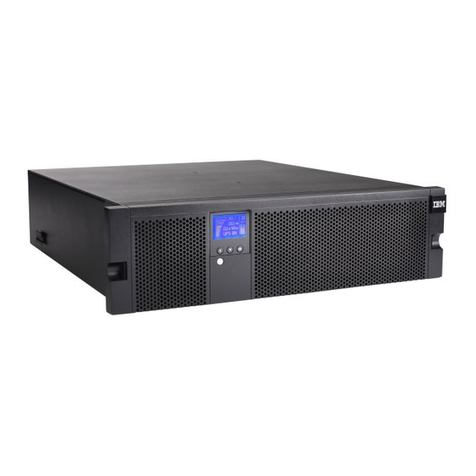
  9. IBM 11000 VA LCD 5U User manual

IBM 11000 VA LCD 5U User manual

򔻐򗗠򙳰 Rack Installation Instructions
For the 11000 VA 5U uninterruptible power supply and 11000
VA 3U extended battery module
Use the instructions in this document to install the IBM®11000 VA LCD 5U Rack UPS and IBM 11000 VA
UPS 3U Extended Battery Module in a rack cabinet.
Review the documentation that comes with your rack cabinet for safety and cabling information.
When you install the uninterruptible power supply (UPS) or extended battery module in a rack cabinet,
observe the following precautions:
vThe extended battery module and UPS internal battery and chassis are heavy. Make sure that you have
the minimum number of persons and equipment that are required to safely lift the components. See
step 7c on page 5 and Table 1 on page 6.
vMake sure that the room air temperature is below 35°C (95°F).
vDo not block any air vents; usually 15 cm (6 in.) of air space provides proper airflow.
vPlan the device installation starting from the bottom of the rack cabinet.
vInstall the heaviest device in the bottom of the rack cabinet.
vDo not extend more than one device out of the rack cabinet at the same time.
vConnect all power cords to properly wired and grounded electrical outlets.
vDo not overload the power outlet when you install multiple devices in the rack cabinet.
You will need a Phillips screwdriver to install the UPS or extended battery module in a rack cabinet.
Note: The illustrations in this document might differ slightly from your hardware.
The following parts come with the rack mounting kit:
vOne right adjustable rail
vOne left adjustable rail
vFour adapter plates with adhesive (for round hole racks)
vSixteen M5 x 16 mm Phillips screws
Note: Removing the rack doors and side panels might make installation easier. See the rack cabinet
documentation for more information.
DANGER
Electrical voltage and current from power, telephone, and communication cables are hazardous.
To avoid a shock hazard:
vDo not connect or disconnect any cables or perform installation, maintenance, or reconfiguration
of this product during an electrical storm.
vConnect all power cords to a properly wired and grounded electrical outlet. Ensure outlet
supplies proper voltage and phase rotation according to the system rating plate.
vConnect any equipment that will be attached to this product to properly wired outlets.
vWhen possible, use one hand only to connect or disconnect signal cables.
vNever turn on any equipment when there is evidence of fire, water, or structural damage.
vDisconnect the attached power cords, telecommunications systems, networks, and modems before
you open the device covers, unless instructed otherwise in the installation and configuration
procedures.
vConnect and disconnect cables as described below when installing, moving, or opening covers on
this product or attached devices.
To Disconnect:
1. Turn everything OFF (unless instructed otherwise).
2. Remove power cords from the outlet.
3. Remove the signal cables from connectors.
4. Remove all cables from devices.
To Connect:
1. Turn everything OFF (unless instructed otherwise).
2. Attach all cables to devices.
3. Attach signal cables to connectors.
4. Attach the power cords to outlets.
5. Turn device ON.
(D005)
CAUTION:
or
>32 kg (70.5 lb)
or 32-55 kg (70.5-121.2 lb)
The weight of this part or unit is between 32 and 55 kg (70.5 and 121.2 lb). It takes three persons to
safely lift this part or unit. (C010)
2
CAUTION:
>55 kg (121.2 lb)
55 kg ( 121.2 lb)
The weight of this part or unit is more than 55 kg (121.2 lb). It takes specially trained persons, a
lifting device, or both to safely lift this part or unit. (C011)
Installing a UPS or extended battery module in the rack cabinet
To install a UPS or extended battery module in the rack cabinet, complete the following steps:
1. For racks with round holes only: Install one adapter plate on each of the ends of the right and left
rails:
a. Locate the four adapter plates that come in the rail kit.
b. Peel off the covering that protects the adhesive side of the adapter plate.
c. Align the adapter plate holes with the holes on one end of a rail.
d. Press firmly to adhere the adapter plate to the end of the rail.
e. Repeat step 1b to step 1d to attach the other adapter plates to the ends of the rails.
3
2. Loosen the rail adjustment screw and adjust the left and right rail length to the depth of the rack
cabinet.
3. Select a location in the bottom of the rack cabinet for the UPS or extended battery module.
4. Secure each rail to the front of the rack with two M5 x 16 mm screws. Make sure that the rails are on
the inside of the rack-cabinet mounting flanges and the letter on each rail faces the inside of the
rack.
5. Secure each rail to the rear of the rack with four M5 x 16 mm screws.
6. Tighten the rail adjustment screws in the middle of each rail.
4
7. For UPS installation only: To reduce the weight of the UPS, remove the internal battery modules:
a. Loosen the thumbscrew on the left battery retention bracket 1, slide the bracket to the right
2, rotate the bracket out 3, and then remove it.
L
b. Loosen the thumbscrew on the right battery retention bracket 1, slide the bracket to the left
2, rotate the bracket out 3, and then remove it.
R
c. Remove the left internal battery module.
Important: Each internal battery module weighs 32 kg (71 lb) and requires three people to safely
lift it.
With the required three people, use the plastic tabs to pull the left internal battery module
completely out of the bay. Place the internal battery module on a sturdy, flat surface.
5
d. Remove the right internal battery module. With the required three people, use the plastic tabs to
pull the right internal battery module completely out of the bay. Place the internal battery
module on a sturdy, flat surface.
If you are installing another UPS, repeat step 7a on page 5 to step 7d.
8. The UPS and extended battery module are very heavy. See the following table to determine the
handling requirements for safely lifting and installing these devices.
Table 1. UPS and extended battery module handling requirements
Machine
type-model or
part number Product description Weight Handling requirement
5395-9KX 11000 VA 5U rack UPS 35 kg (77 lb) (without internal
battery modules)
Three persons
69Y1986 11000 VA 3U extended battery
module
79 kg (174 lb) Specially trained persons, a
lifting device, or both
9. Using the handling requirements in Table 1, align the rear hold-down brackets on the sides of the
UPS or extended battery module with the inner rails. Carefully slide the UPS or extended battery
module into the rack cabinet.
Rear
hold-down
bracket
10. Secure the front of the UPS or extended battery module to the rack cabinet with four M5 x 16 mm
screws.
6
11. For UPS installation only: To reinstall the internal battery modules, complete the following steps:
a. With the required three people, carefully slide one battery module into the UPS. Repeat this step
for the second battery module.
b. Connect the three internal battery connectors.
Note: A small amount of arcing might occur when you connect the batteries. This is normal and
does not damage the unit or present any safety concern.
c. Reinstall the right battery retention bracket:
1) Slide the right battery retention bracket to the left and into the slot 1.
R
2) Rotate the battery retention bracket toward the UPS 2. Make sure that the internal battery
connectors are out of the way.
3) Slide the battery retention bracket to the right 3.
4) Tighten the thumbscrew on the right battery retention bracket 4.
7
d. Reinstall the left battery retention bracket:
1) Slide the left battery retention bracket to the right and into the slot 1.
L
2) Rotate the battery retention bracket toward the UPS 2. Make sure that the internal battery
connectors are out of the way.
3) Slide the battery retention bracket to the left 3.
4) Tighten the thumbscrew on the left battery retention bracket 4.
12. Install the bezel:
vFor a UPS:
a. Locate the upper and lower bezels that come with the UPS. The upper bezel has an opening
for the liquid crystal display (LCD).
b. To install the UPS upper bezel, press the two side latches toward each other, align the bezel so
that it goes over the LCD on the front of the UPS, and snap it into place.
Upper
bezel
Lower
bezel
c. To install the UPS lower bezel, press the two side latches toward each other, align the bezel
underneath the upper bezel, and snap it into place.
8
vFor an extended battery module: Locate the bezel that comes with the extended battery module.
Press the two side latches toward each other, align the bezel with the extended battery module,
and snap it into place.
13. Remove the clear protective film that covers the LCD on the front of the UPS.
For more information about installing and operating the UPS and extended battery module, see the
Installation and Maintenance Guide that comes with the UPS.
Important: Before you ship the UPS in a rack cabinet, you must install a shipping bracket in front of the
UPS for extra protection. For more information, see “Installing the shipping bracket on the
UPS” on page 10.
Store this information with your UPS documentation for future use.
9
Installing the shipping bracket on the UPS
You must install the shipping bracket on the front of the UPS before the UPS is shipped installed in a
rack cabinet. The shipping bracket provides extra protection for the UPS during shipment.
To install the shipping bracket, complete the following steps:
1. If the UPS bezels are installed, remove the lower front bezel. Press the two side latches toward each
other to release the bezel, and pull the bezel away. Keep the bezel.
OK
OK
100%
6
min
2. Make sure that the UPS internal batteries are disconnected. For more information, see the Installation
and Maintenance Guide on the IBM Documentation CD that comes with the UPS.
3. Remove the four screws that secure the front of the UPS to the rack cabinet. Keep the four screws.
4. Align the shipping bracket with the lower front of the UPS, with the support lip under the UPS.
OK
OK
100%
6
min
Shipping bracket
5. Secure the shipping bracket and the UPS to the rack cabinet with the four screws that you removed in
step 3.
6. To attach the UPS lower front bezel, press the two side latches toward each other, align the bezel over
the shipping bracket, and snap it into place.
10
Removing the shipping bracket from the UPS
If the UPS was shipped installed in a rack cabinet, a shipping bracket is installed to provide extra
protection for the UPS during shipment. Before using the UPS, remove the shipping bracket on the front
of the UPS.
To remove the shipping bracket, complete the following steps:
1. If the UPS lower front bezel is installed, remove it. Press the two side latches toward each other to
release the bezel, and pull the bezel away. Keep the bezel.
OK
OK
100%
6
min
2. Remove the four screws that secure the shipping bracket and the UPS to the rack cabinet. Keep the
four screws.
OK
OK
100%
6
min
Shipping bracket
3. Remove the shipping bracket and save it in case you have to ship the UPS in the rack cabinet in the
future.
4. Secure the front of the UPS to the rack cabinet with the four screws that you removed in step 2.
5. If you are connecting the UPS internal batteries, see the Installation and Maintenance Guide on the IBM
Documentation CD that comes with the UPS.
6. To attach the UPS lower front bezel, press the two side latches toward each other, align the bezel
underneath the upper bezel, and snap it into place.
11
First Edition (February 2011)
IBM is a trademark of International Business Machines Corporation in the United States, other countries, or both.
Other company, product, or service names may be trademarks or service marks of others.
Printed in USA
© Copyright IBM Corporation 2011.
US Government Users Restricted Rights – Use, duplication or disclosure restricted by GSA ADP Schedule Contract
with IBM Corp.
(1P) P/N: 81Y5427

Other manuals for 11000 VA LCD 5U

2

This manual suits for next models

1

Other IBM Power Supply manuals

IBM System/370 145 Service manual

IBM

IBM System/370 145 Service manual

IBM 9006-22C Instruction Manual

IBM

IBM 9006-22C Instruction Manual

IBM Power System AC922 User manual

IBM

IBM Power System AC922 User manual

IBM PurePower System Instruction Manual

IBM

IBM PurePower System Instruction Manual

IBM I 7.1 Installation guide

IBM

IBM I 7.1 Installation guide

IBM 170 Servers User manual

IBM

IBM 170 Servers User manual

IBM 1500VA User manual

IBM

IBM 1500VA User manual

IBM 8203-E4A User manual

IBM

IBM 8203-E4A User manual

IBM S822LC User guide

IBM

IBM S822LC User guide

IBM Power Systems 8005-12N Instruction Manual

IBM

IBM Power Systems 8005-12N Instruction Manual

IBM 5786 Use and care manual

IBM

IBM 5786 Use and care manual

IBM Power System 9009-41A User manual

IBM

IBM Power System 9009-41A User manual

IBM POWER 730 User manual

IBM

IBM POWER 730 User manual

IBM Power System 9009-41A User manual

IBM

IBM Power System 9009-41A User manual

IBM Power System 5105-22E User manual

IBM

IBM Power System 5105-22E User manual

IBM S922L Instruction Manual

IBM

IBM S922L Instruction Manual

IBM Power System AC922 User manual

IBM

IBM Power System AC922 User manual

IBM 9009-22A User manual

IBM

IBM 9009-22A User manual

IBM Power Systems EMX0 PCIe Gen3 Instruction Manual

IBM

IBM Power Systems EMX0 PCIe Gen3 Instruction Manual

IBM Power System L922 User manual

IBM

IBM Power System L922 User manual

IBM S824L Instruction Manual

IBM

IBM S824L Instruction Manual

IBM Power System IC922 User manual

IBM

IBM Power System IC922 User manual

IBM 9006-12C User manual

IBM

IBM 9006-12C User manual

IBM 7199-92X User manual

IBM

IBM 7199-92X User manual

Popular Power Supply manuals by other brands

Zendure Satellite Monitor CT installation manual

Zendure

Zendure Satellite Monitor CT installation manual

Neumann.Berlin BS 48 i owner's manual

Neumann.Berlin

Neumann.Berlin BS 48 i owner's manual

Televes MATV 5021 manual

Televes

Televes MATV 5021 manual

MSI MEG Ai1300P PCIE5 user guide

MSI

MSI MEG Ai1300P PCIE5 user guide

Tiptop Audio ZEUS Series microZEUS user guide

Tiptop Audio

Tiptop Audio ZEUS Series microZEUS user guide

Trinabess Trinahome T Series installation manual

Trinabess

Trinabess Trinahome T Series installation manual

Samlexpower SEC-1235 Installation & operating manual

Samlexpower

Samlexpower SEC-1235 Installation & operating manual

Videotec OHEPS19B instruction manual

Videotec

Videotec OHEPS19B instruction manual

EA-ELEKTRO-AUTOMATIK PS 2042-06B instruction manual

EA-ELEKTRO-AUTOMATIK

EA-ELEKTRO-AUTOMATIK PS 2042-06B instruction manual

Puls CP10 Series instruction manual

Puls

Puls CP10 Series instruction manual

BEL LDN120 Series installation instructions

BEL

BEL LDN120 Series installation instructions

AP&T AP-AB1208 manual

AP&T

AP&T AP-AB1208 manual

Kikusui PWR400L Operation manual

Kikusui

Kikusui PWR400L Operation manual

Honeywell SILENT KNIGHT SK-PS6 instruction manual

Honeywell

Honeywell SILENT KNIGHT SK-PS6 instruction manual

EMC2 302-000-589 Disassembly instructions

EMC2

EMC2 302-000-589 Disassembly instructions

Panasonic 4466 Technical description

Panasonic

Panasonic 4466 Technical description

Pyramid PS15K.5 user manual

Pyramid

Pyramid PS15K.5 user manual

BEL LDN240 Series installation instructions

BEL

BEL LDN240 Series installation instructions

manuals.online logo
manuals.online logoBrands
  • About & Mission
  • Contact us
  • Privacy Policy
  • Terms and Conditions

Copyright 2025 Manuals.Online. All Rights Reserved.