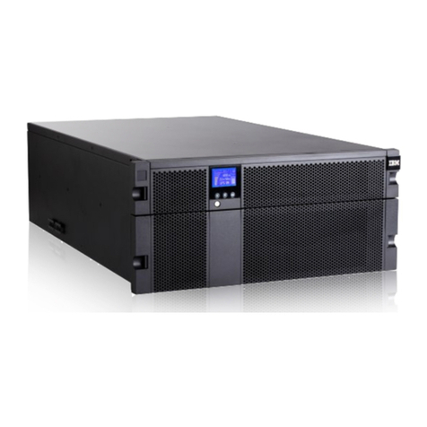
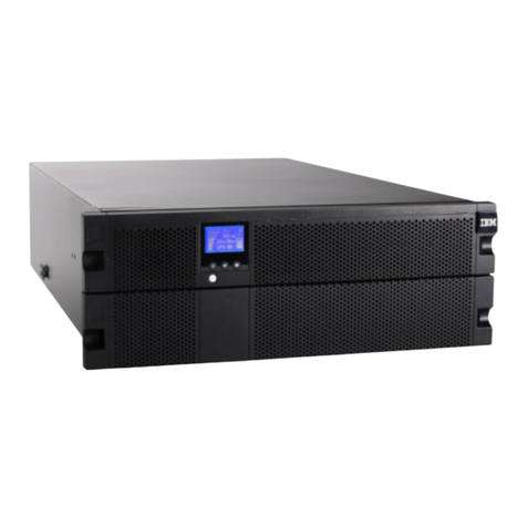
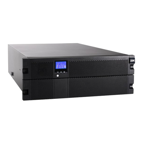
IBM 5000XHV User manual

1
5000XHV -UNINTERRUPTIBLE POWER SUPPLY -QUICK INSTALLATION GUIDE
46M5391
1: OVERVIEW
ATTENTION:
•Read the Safety Instructions before installing the uninterruptible power supply.
•The uninterruptible power supply and battery modules are heavy. Select a location sturdy enough to handle the weight.
•Refer to the Uninterruptible Power Supply Operation and Setup Guide for information on how to obtain service and support for the
unit.
NOTE:Illustrations in this document might vary in appearance from the purchased unit.
•Utility knife or scissors
•Two Phillips screwdrivers (#1 and #2)
•One wrench (10mm)
•Cage nut insertion tool or flat-blade screwdriver (for installing cage nuts in some rack cabinets)
Inventory
Quick Installation Guide
Important Notices Flyer
Documentation
Warranty Flyer
PowerChute
Business Edition
software CD
Network Management Card documentation CD

2
2: INSTALLATION
DANGER
To prevent a possible shock from touching two surfaces with different protective ground (earth), use one hand, when possible,
to connect or disconnect signal cables. (D001)
DANGER
When working on or around the system, observe the following precautions:
Electrical voltage and current from power, telephone, and communication cables are hazardous. To avoid a shock hazard:
•Connect power to this unit only with the IBM provided power cord. Do not use the IBM provided power cord for any other
product.
•Do not open or service any power supply assembly.
•Do not connect or disconnect any cables or perform installation, maintenance, or reconfiguration of this product during an
electrical storm.
•The product might be equipped with multiple power cords. To remove all hazardous voltages, disconnect all power cords.
•Connect all power cords to a properly wired and grounded electrical outlet. Ensure that the outlet supplies proper voltage and
phase rotation according to the system rating plate.
•Connect any equipment that will be attached to this product to properly wired outlets.
•When possible, use one hand only to connect or disconnect signal cables.
•Never turn on any equipment when there is evidence of fire, water, or structural damage.
•Disconnect the attached power cords, telecommunications systems, networks, and modems before you open the device covers,
unless instructed otherwise in the installation and configuration procedures.
•Connect and disconnect cables as described in the following procedures when installing, moving, or opening covers on this
product or attached devices.
To disconnect:
1. Turn off everything (unless instructed otherwise).
2. Remove the power cords from the outlets.
3. Remove the signal cables from the connectors.
4. Remove all cables from the devices.
To connect:
5. Turn off everything (unless instructed otherwise).
6. Attach all cables to the devices.
7. Attach the signal cables to the connectors.
8. Attach the power cords to the outlets.
9. Turn on the devices.
(D005)

3
DANGER
Uninterruptible power supply (UPS) units contain specific hazardous materials. Observe the following precautions if your
product contains a UPS:
•The UPS contains lethal voltages. All repairs and service must be performed only by an authorized service support representa-
tive. There are no user serviceable parts inside the UPS.
•The UPS contains its own energy source (batteries). The output receptacles might carry live voltage even when the UPS is not
connected to an AC supply.
•Do not remove or unplug the input cord when the UPS is turned on. This removes the safety ground from the UPS and the
equipment connected to the UPS.
•The UPS is heavy because of the electronics and batteries that are required. To avoid injury, observe the following precautions:
°Do not attempt to lift the UPS by yourself. Ask another service representative for assistance.
°Remove the battery, electronics assembly, or both from the UPS before removing the UPS from the shipping carton
or installing or removing the UPS in the rack. (D007)
CAUTION
Energy hazard present. Shorting might result in system outage and possible physical injury.
Remove all metallic jewelry before servicing. (C001)
CAUTION
Lead-acid batteries can present a risk of electrical burn from high, short-circuit current. Avoid battery contact with metal materials;
remove watches, rings, or other metal objects, and use tools with insulated handles. To avoid possible explosion, do not burn.
Exchange only with the IBM-approved part. Recycle or discard the battery as instructed by local regulations. In the United States,
IBM has a process for the collection of this battery. For information, call 1-800-426-4333. Have the IBM part number for the battery
unit available when you call. (C004)
CAUTION
or
>32 kg (70.5 lb)
or
32-55 kg (70.5-121.2 lb)
The weight of this part or unit is between 32 and 55 kg (70.5 and 121.2 lb). It takes three persons to safely lift this unit. (C010)
CAUTION
To avoid personal injury, before lifting this unit, remove all appropriate subassemblies per instructions to reduce the system weight.
(C012)

4
Removing the Battery Modules
XRemove the two screws that secure the
battery compartment door. YOpen the battery compartment door.
ZRemove the battery modules. [Close the battery compartment door.
Installing the Uninterruptible Power Supply in a Rack
XSecure the rack-mount brackets to the
uninterruptible power supply. YRefer to the instruction sheet included in the rail kit for rail installation
details. Refer to the diagram below for cage nut (clip nut) installation. The
solid squares indicate the cage nut (clip nut) locations. Install the
uninterruptible power
supply at the bottom of the rack.
Note: Leave 3 U of space below the uninterruptible power supply for each
battery pack to be installed.
ZSecure the uninterruptible power supply in the rack using four Phillips hex screws.

5
Installing and Connecting the Batteries and Attaching the Bezel
CAUTION
Energy hazard present. Shorting might result in system outage and possible physical injury.
Remove all metallic jewelry before servicing. (C001)
XOpen the battery compartment door. YInstall the battery modules.
ZConnect the battery modules. [Close the battery compartment door.
Be sure the battery cables are positioned so that they are not pinched.
Secure the battery compartment door using the
screws removed previously. Attach the bezel.

6
Rear Panel Components
INDEX ITEM DESCRIPTION
Outlets Connect equipment to the uninterruptible power supply.
Output Circuit Breakers Circuit breakers protect the UPS outlets from overload conditions.
TVSS Screw The uninterruptible power supply features a transient voltage surge-suppression (TVSS)
screw for connecting the ground lead on surge suppression devices such as telephone
and network line protectors. When connecting a grounding cable, disconnect the
uninterruptible power supply from the utility power outlet.
Serial Port Power management software and serial port communication can be used with the
uninterruptible power supply. Use only cables supplied or approved by IBM.
Note: Use the supplied serial cable to connect to the serial port. Do not use a standard
serial interface cable because it is incompatible with the uninterruptible power supply
connector.
Bypass Switch This switch will put the unit in bypass mode. See Operation.
EPO Terminal The optional Emergency Power Off (EPO) feature enables connected loads to be
immediately de-energized from a remote location, without switching to battery
operation. See Emergency Power Off (EPO) Option.
Network Management Card The Network Management Card (NMC) is factory installed in the uninterruptible power
supply.
Link-RX/TX (10/100) LED Refer to the NMC documentation for details.
Status LED Refer to the NMC documentation for details.
Reset on the NMC Resets the NMC while the unit is connected to utility or battery power.
Ethernet Port on the NMC Connects the uninterruptible power supply to the Ethernet network.
Universal Input/Output
Connectors on the NMC Connect temperature sensors, temperature/humidity sensors, or relay input/output
connectors. Refer to the NMC documentation for details.
USB Connectors on NMC Reserved for future use.
Console on the NMC Connects the NMC to a local computer for initial configuration of network settings.
Provides access to the command line interface.
Optional Battery Pack
Connectors Optional battery packs provide extended runtime during power outages.
See 3U Extend Run Battery Pack Operation and Setup Guide.
Input Fuse The input fuse provides protection for the uninterruptible power supply from extreme
overloads.
Input power connector Input power cord connects the uninterruptible power supply to utility power.

7
3: COMMUNICATION OPTIONS
There are two different management options available: network interface or serial interface. (See Rear Panel Components for
identification of ports.) These options cannot be used simultaneously.
OPTION A: NETWORK MANAGEMENT CARD CONFIGURATION
The Network Management Card, installed in the uninterruptible power supply at the factory, allows remote configuration, control, and
monitoring of the uninterruptible power supply over the network. The interface allows full control and configuration of uninterrupti-
ble power supply parameters through a Web browser. Through its standard features, the Network Management Card does the follow-
ing:
•Generates system log (Syslog) messages
•Allows using a BOOTP or Dynamic Host Configuration Protocol (DHCP) server to provide the TCP/IP values the Net-
work
Management Card needs for network communication
•Detects 10/100 Mbps connection speeds
•Provides an event log and a data log accessible by FTP, Secure CoPy (SCP), or a Web browser
•Provides uninterruptible power supply scheduling features
•Provides graceful, unattended shutdown for multiple servers in the event of an extended power outage, through the
PowerChute®Network Shutdown utility,included on the Network Management Card CD
•Generates e-mail notifications for uninterruptible power supply or system events
•Limits SNMP traps and e-mail notifications based on the severity level of the events
•Provides tools to configure one or more Network Management Cards over the network
•Provides enhanced security
To configure the pre-installed Network Management Card of your uninterruptible power supply using this network interface option,
refer to Chapter 3, Option A: Network Management Card Configuration on the Network Management Card documentation CD.
OPTION B: UTILIZATION OF SERIAL CONNECTION THROUGH POWERCHUTE BUSINESS EDITION SOFTWARE
The uninterruptible power supply comes with a PowerChute Business Edition (PCBE) CD to monitor and manage the uninterruptible
power supply. See PCBE Installation Instructions found on the PCBE CD.
PCBE includes the following features:
•Provides communication via serial connection (all supported operating systems) or USB (Microsoft®Windows®XP and
Windows 2000 only)
•Provides graceful, unattended shutdown in the event of an extended power outage
•Provides a data and event log
•Provides uninterruptible power supply scheduling features
•Generates e-mail notifications for uninterruptible power supply or system events
•Enables quick assessment of your equipment status through the Centralized Management Console
To install and configure using this option, see Chapter 4, Option B: Managing the Uninterruptible Power Supply System with
PowerChuteBusiness Edition Software on page 12.

8
4: OPTION A: NETWORK MANAGEMENT CARD CONFIGURATION
Note: If a default gateway is unavailable, use the IP address of a computer that is located on the same subnet as the Network
Management Card and that is usually running. The Network Management Card uses the default gateway to test the network when
traffic is very light.
Caution: Do not use the loopback address (127.0.0.1) as the default gateway address for the Network Management Card. It disables
the card and requires you to reset TCP/IP settings to their defaults using a local serial login.
See “Watchdog Features” in the “Introduction” of the Network Management Card User’s Guide for more information about the
watchdog role of the default gateway.
TCP/IP configuration methods
Use one of the following methods to define the TCP/IP settings needed by the Network Management Card:
•APC Device IP Configuration Wizard (See “APC Device IP Configuration Wizard” on page 8.)
•BOOTP or DHCP server (See “BOOTP and DHCP configuration” on page 8.)
•Networked computer (See “Local access to the command line interface” on page 9 or “Remote access to the command line
interface” on page 10.)
APC device IP configuration wizard
You can use the APC Device IP Configuration Wizard at a computer running Microsoft® Windows® 2000, Windows Server® 2003,
or Windows XP to discover unconfigured Network Management Cards and configure their basic TCP/IP settings, one card at a time,
over the network.
Note: Most software firewalls must be temporarily disabled for the Wizard to discover unconfigured Network Management Cards.
1. If autorun is enabled, the user interface of the CD starts when you insert the APC Network Management Card Utility CD into
a computer on your network. Otherwise, open the file contents.htm on the CD.
2. Select the Device IP Configuration Wizard from the main menu.
3. When the Wizard discovers the unconfigured Network Management Card, follow the on-screen instructions.
Note: If you leave the option Start a Web browser when finished enabled, you can access the Network Management Card through
your browser by using apc (the default) for both the user name and password.
.ini file utility
You can use the .ini file export utility to export .ini file settings from configured Network Management Cards to one or more
unconfigured Network Management Cards. The utility and documentation are included on the APC Network Management Card
Utility CD.
BOOTP and DHCP configuration
The default TCP/IP configuration setting, BOOTP & DHCP, assumes that a properly configured BOOTP or DHCP server is
available to provide TCP/IP settings to Network Management Cards. The Network Management Card first attempts to discover a
properly configured BOOTP server, and then a DHCP server. It repeats this pattern until it discovers a BOOTP or DHCP server.
A user configuration (.ini) file can function as a BOOTP or DHCP boot file. For more information, see the TCP/IP configuration
section of the Network Management Card User’s Guide, available from the Utility CD or the APC Web site, www.apc.com.
If neither of these servers is available, see “APC Device IP Configuration Wizard” on page 8, “Local access to the command line
interface” on page 9, or “Remote access to the command line interface” on page 14 to configure the needed TCP/IP settings.

9
BOOTP. For the Network Management Card to use a BOOTP server to configure its TCP/IP settings, it must find a properly
configured RFC951-compliant BOOTP server.
In the BOOTPTAB file of the BOOTP server, enter the Network Management Card’s MAC address, IP address, subnet mask, and
default gateway, and, optionally, a bootup file name. Look for the MAC address on the bottom of the Network Management Card or
on the Quality Assurance slip included in the package.
When the Network Management Card reboots, the BOOTP server provides it with the TCP/IP settings.
•If you specified a bootup file name, the Network Management Card attempts to transfer that file from the BOOTP server using
TFTP or FTP. The Network Management Card assumes all settings specified in the bootup file.
•If you did not specify a bootup file name, you can configure the other settings of the Network Management Card remotely
through its Web interface or command line interface; the user name and password are both apc, by default.
To create a bootup file, see your BOOTP server documentation.
DHCP. You can use an RFC2131/RFC2132-compliant DHCP server to configure the TCP/IP settings for the Network Management
Card.
This section summarizes the Network Management Card’s communication with a DHCP server. For more detail about how a DHCP
server can configure the network settings for a Network Management Card, see “DHCP Configuration” in the Network Management
Card User’s Guide on the Utility CD.
1. The Network Management Card sends out a DHCP request that uses the following to identify itself:
•A Vendor Class Identifier (APC by default)
•A Client Identifier (by default, the MAC address of the Network Management Card)
•A User Class Identifier (by default, the identification of the application firmware installed on the Network Management
Card)
2. A properly configured DHCP server responds with a DHCP offer that includes all the settings that the Network Management
Card needs for network communication. The DHCP offer also includes the Vendor Specific Information option
(DHCP option 43). By default, the Network Management Card ignores DHCP offers that do not encapsulate the APC cookie
in DHCP option 43 using the following hexadecimal format: Option 43 = 01 04 31 41 50 43
where
•the first byte (01) is the code
•the second byte (04) is the length
•the remaining bytes (31 41 50 43) are the APC cookie.
See your DHCP server documentation to add code to the Vendor Specific Information option.
Note: To disable the requirement that a DHCP offer include the APC cookie, clear the check box Require vendor specific cookie to
accept DHCP Address in the Web interface: Administration > Network>TCP/IP>DHCP.
Alternately, at the command line interface, use this command to disable the DHCP cookie requirement: boot -c disable
Local access to the command line interface
You can use a computer connected to the serial port on the front of the Network Management Card to access the command line
interface.
1. Select a serial port at the local computer, and disable any service that uses that port.
2. Use the provided serial cable (IBM part number 46M5366) to connect the selected port to the serial port on the front panel of
the Network Management Card.
3. Run a terminal program (such as HyperTerminal) and configure the selected port for 9600 bps, 8 data bits, no parity, 1 stop
bit, and no flow control. Save the changes.
4. Press Enter, repeatedly if necessary, to display the User Name prompt.
5. Use apc for the user name and password.
See “Command line interface” on page 10 to finish the configuration.
10
Remote access to the command line interface
From any computer on the same network as the Network Management Card, you can use ARP and Ping to assign an IP address to the
Network Management Card, and then use Telnet to access its command line interface and configure the other TCP/IP settings.
Note: After the Network Management Card has its IP address configured, you can use Telnet, without first using ARP and Ping, to
access that Network Management Card.
1. Use the MAC address of the Network Management Card in the ARP command to define the IP address.
Note: Look for the MAC address on the bottom of the Network Management Card or on the Quality Assurance slip included in the
package.
For example, to define 156.205.14.141 as the IP address of a Network Management Card with 00 c0 b7 63 9f 67 as its MAC address,
use one of the following commands:
•Windows command format: arp -s 156.205.14.141 00-c0-b7-63-9f-67
•LINUX command format: arp -s 156.205.14.141 00:c0:b7:63:9f:67
2. Use Ping with a size of 113 bytes to assign the IP address defined by the ARP command. For the IP address defined in step 1,
use one of the following commands:
•Windows command format: ping 156.205.14.141 -l 113
•LINUX command format: ping 156.205.14.141 -s 113
3. Use Telnet to access the Network Management Card at its newly assigned IP address. For example: telnet 156.205.14.141
4. Use apc for both user name and password.
See “Command line interface” on page 10 to finish the configuration.
Command line interface
After you log on at the command line interface, as described in “Local access to the command line interface” on page 13 or “Remote
access to the command line interface” on page 10, you can manually configure network settings.
1. Contact your network administrator to obtain the IP address, subnet mask, and default gateway for the Network Management
Card.
2. Use these three commands to configure network settings. (Text in italics indicates a variable.)
a. tcpip -i yourIPaddress
b. tcpip -s yourSubnetMask
c. tcpip -g yourDefaultGateway
For each variable, type a numeric value that has the format xxx.xxx.xxx.xxx.
For example, to set a system IP address of 156.205.14.141, type the following command and press Enter:
tcpip -i 156.205.14.141
Type exit. The Network Management Card restarts to apply the changes.

11
HOW TO MANAGE THE UNINTERRUPTIBLE POWER SUPPLY THROUGH A
CONFIGURED NETWORK MANAGEMENT CARD
Once the Network Management Card is running on your network, you can use the following interfaces to monitor and configure the
Network Management Card.
For the control console:
•Telnet and FTP for standard security levels.
•SSH (Secure SHell) for high security.
For the Web interface:
•The default setting for standard HTTP access.
•SSL (Secure Sockets Layer) for high-security HTTPS access.
To log on through the Web interface initially, at standard security levels:
1. Use Microsoft Internet Explorer 5.0 (or later) or Netscape 4.0.8 (or later, except Netscape 6.x).
2. Address the Network Management Card by its IP address or DNS name (if configured).
3. Enter the User Name and Password (apc by default).
For SNMP, use a MIB Browser and the supplied MIB to monitor and configure the Network Management Card of the uninterruptible
power supply through SNMP. When using high-security access, disable SNMP.
Note: For more information about how to use any of these interfaces and about how to configure high-security access, see the User's
Guide on the Network Management Card CD.
PowerChute Network Shutdown
The PowerChute Network Shutdown (PCNS) utility that is included on the Network Management Card CD can provide reliable, grace-
ful, unattended shutdown for multiple servers protected by the uninterruptible power supply in the event of an extended power outage.
It works by communicating directly over the network to the Network Management Card CD. To install PCNS, see the installation guide
in the PCNS directory on the Network Management Card CD.

12
5: OPTION B: MANAGING THE UNINTERRUPTIBLE POWER SUPPLY SYSTEM WITH
POWERCHUTEBUSINESS EDITION SOFTWARE
The PowerChute®Business Edition (PCBE) software has three components: PCBE Server, PCBE Agent, and PCBE Console,
identified in the illustration below:
•The PCBE Agent communicates with the uninterruptible power supply and with the PCBE Server. It provides
uninterruptible power supply status monitoring and, in the event of an extended power outage, system shutdown capabilities
for the uninterruptible power supply protected computers.
Important: An uninterruptible power supply can only protect one computer running a PCBE Agent at a time.
•The PCBE Server can monitor several uninterruptible power supply systems through the PCBE Agents. It provides
centralized event tracking and event notification.
•The PCBE Console is a user interface that enables the user log on to any PCBE Server and manage the uninterruptible power
supply systems connected to that server.
(With the Single Node PCBE package, the user can install just the Agent component for a simpler monitoring system).
INSTALLING POWERCHUTE BUSINESS EDITION
The user can install all three PCBE components on the same computer or on different computers on the network. The PCBE Agent
component, however, must be installed on a computer that is connected to an uninterruptible power supply with the supplied serial
cable.
For Windows Operating Systems
Follow these steps to install the standard 5-Node PCBE package:
1. Insert the PowerChute Business Edition CD.
2. Click Getting Started Guide to read an overview of the PCBE components and the installation procedures.
3. After reviewing the guide, click Install Product on the initial screen.
4. Click Release Notes and review that document.
5. Click Install, and follow the on-screen instructions to install the components in the correct order: first, the PCBE Agents,
then the PCBE Server, and finally the PCBE Console.
After the PCBE components have been installed, use the PCBE Console to log on to any PCBE Server and use the Context Help or
Help Contents options in the Help menu to review the online help.
For Linux
See the relevant readme file on the CD: Linux/LinuxReadme.txt.

13
ADDING PCBE AGENTS TO A PCBE SERVER DEVICE LIST
During the installation of a PCBE Server, select up to five PCBE Agents for that Server to monitor:
•The PCBE Agents must already be installed.
•The PCBE Agents must use the same password and user name as the PCBE Server.
It is possible to install PCBE Agents after the initial installation. These Agents can be added to the device list of any PCBE Server that
uses the same password and user name.
Follow these steps:
1. Use PCBE Console to log on to the PCBE Server.
2. Select Configure Device List from the Tools menu.
3. Highlight a PCBE Agent to be added in the Discovered Devices list and click Add.
4. Repeat step 3 for each PCBE Agent to be added.
5. Click Apply to add the PCBE Agents to the server device list.

14
6: OUTPUT VOLTAGE SELECTION
Terminal Mode is a menu driven interface that enables enhanced configuration of the uninterruptible power supply through a serial
connection.
Connect the serial cable to the serial port on the rear side of the uninterruptible power supply.
1. When using the PowerChute®Business Edition or Network Shutdown software, stop the PowerChute Business Edition agent and
server services using the following steps:
a. From the desktop, click Start=> Settings=> Control Panel=> Administrative Tools=> Services.
b. Select PCBE Server and PCBE Agent or APC PBE Agent, then, right click the mouse and select Stop.
2. The Network Management Card (NMC) is factory installed in the IBM 5000XHV SmartSlot located on the rear panel. The NMC
must be removed from the SmartSlot prior to uninterruptible power supply terminal mode configuration.
Remove the two screws that secure the NMC to the uninterruptible power supply chassis. Carefully remove the NMC.
3. Open a terminal program, for example HyperTerminal.
From the desktop, click Start => Programs => Accessories => Communication =>HyperTerminal.
4. Double-click on the HyperTerminal icon.
a. Follow the prompts to choose a name and select an icon. Disregard the message, must install a modem, if it is displayed. Click
OK.
b. Select the COM port that is connected to the uninterruptible power supply. The port settings are:
9bits per second - 9600
9data - bits 8
9parity - none
9stop bit - 1
9flow control - none
c. Click Enter.
5. Once the blank terminal window is open, follow these steps to configure the output voltage:
a. Press Enter to initiate terminal mode.
b. Press 1to select uninterruptible power supply Settings. Wait for the uninterruptible power supply Settings menu to appear on
the screen.
c. Press 1to select Output Voltage.
d. Select the number corresponding to the desired voltage setting, then press Yto confirm.
f. Press Esc multiple times until logged out.
6. Reinstall the NMC using the two screws previously removed.
7. Start the PowerChute Business Edition agent and server services using the following steps:
a. From the desktop, click Start=> Settings=> Control Panel=> Administrative Tools=> Services.
b. Select PCBE Server and PCBE Agent or APC PBE Agent; then, right click the mouse and select Start.
©Copyright International Business Machines Corporation 2009. All rights reserved.
U.S. Government Users – Restricted rights –
Use, duplication or disclosure is subject to restrictions set forth in GSA ADP Schedule Contract with IBM Corp.
Trademarks
IBM is trademark of International Business Machines Corporation in the United States, other countries, or both. APC and PowerChute are registered
trademarks of American Power Conversion Corporation. Microsoft, Windows, Windows Me, Windows NT, and Windows XP are trademarks of Microsoft
Corporation in the United States, other countries, or both. Other company, product, or service names may be trademarks or service marks of others.
Table of contents
Other IBM UPS manuals

IBM
IBM System Storage TS3100 Manual

IBM
IBM 700 RM UPS User manual

IBM
IBM UPS 7500XHV User manual

IBM
IBM 1500VA User manual

IBM
IBM 6000 VA LCD 4U Product manual

IBM
IBM 3000XLV User manual

IBM
IBM 2200VA LCD 2U User manual

IBM
IBM 5595-1AX User manual

IBM
IBM 11000 VA LCD 5U User manual

IBM
IBM 6000 VA LCD 4U User manual