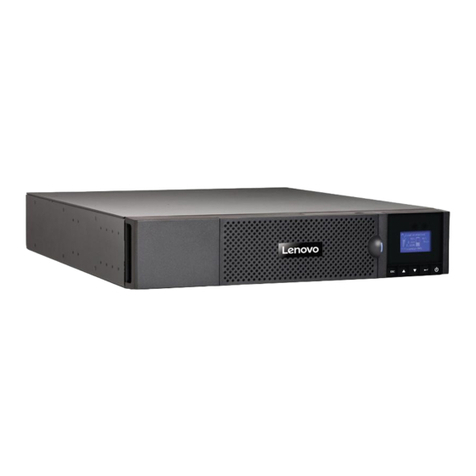
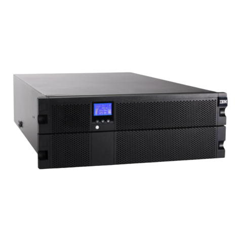
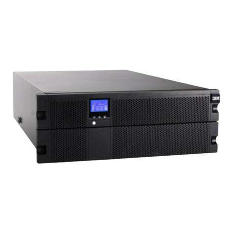
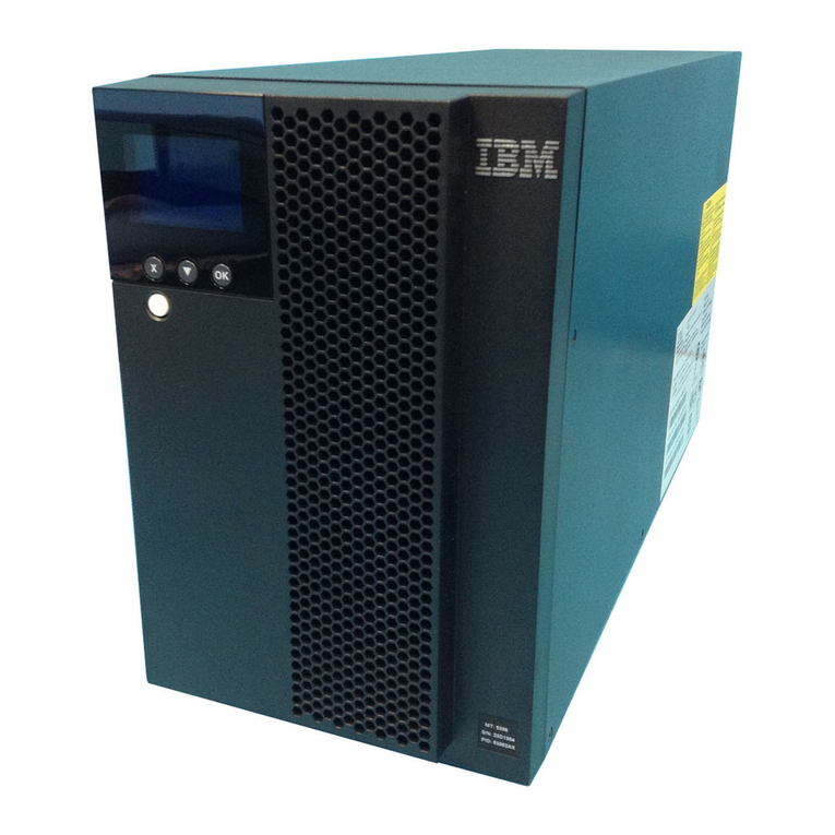
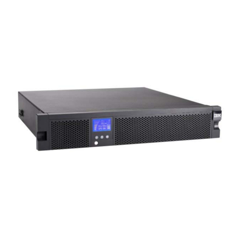
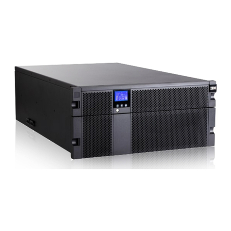
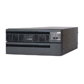
IBM 6000 VA LCD 4U Product manual

6000VALCD4URackUPS
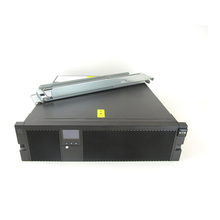
6000 VA UPS 3U Extended Battery Module
Installation and Maintenance Guide


6000VALCD4URackUPS
6000 VA UPS 3U Extended Battery Module
Installation and Maintenance Guide

Note: Before using this information and the product it supports, read the general information in Appendix B, “Notices,” on page 61,
the Safety Information and Environmental Notices and User Guide documents on the IBM Documentation CD, and the Warranty
Information document that comes with the product.
Second Edition (June 2012)
© Copyright IBM Corporation 2010, 2012.
US Government Users Restricted Rights – Use, duplication or disclosure restricted by GSA ADP Schedule Contract
with IBM Corp.

Safety
Before installing this product, read the Safety Information.
Antes de instalar este produto, leia as Informações de Segurança.
Læs sikkerhedsforskrifterne, før du installerer dette produkt.
Lees voordat u dit product installeert eerst de veiligheidsvoorschriften.
Ennen kuin asennat tämän tuotteen, lue turvaohjeet kohdasta Safety Information.
Avant d'installer ce produit, lisez les consignes de sécurité.
Vor der Installation dieses Produkts die Sicherheitshinweise lesen.
Prima di installare questo prodotto, leggere le Informazioni sulla Sicurezza.
Les sikkerhetsinformasjonen (Safety Information) før du installerer dette produktet.
Antes de instalar este produto, leia as Informações sobre Segurança.
© Copyright IBM Corp. 2010, 2012 iii

Antes de instalar este producto, lea la información de seguridad.
Läs säkerhetsinformationen innan du installerar den här produkten.
Important:
Each caution and danger statement in this document is labeled with a number. This
number is used to cross reference an English-language caution or danger
statement with translated versions of the caution or danger statement in the Safety
Information document.
For example, if a caution statement is labeled “Statement 1,” translations for that
caution statement are in the Safety Information document under “Statement 1.”
Be sure to read all caution and danger statements in this document before you
perform the procedures. Read any additional safety information that comes with the
server or optional device before you install the device.
DANGER
Hazardous voltage, current, or energy levels are present inside any
component that has this label attached. Do not open any cover or barrier
that contains this label.
(L001)
CAUTION:
The product might be equipped with a hard-wired power cable. Ensure that a
licensed electrician performs the installation per the national electrical code.
(C022)
iv 6000 VA UPS and 6000 VA EBM: Installation and Maintenance Guide

DANGER
When working on or around the system, observe the following precautions:
Electrical voltage and current from power, telephone, and communication
cables are hazardous. To avoid a shock hazard:
vConnect power to this unit only with the provided power cord. Do not
use the provided power cord for any other product.
vDo not open or service any power supply assembly.
vDo not connect or disconnect any cables or perform installation,
maintenance, or reconfiguration of this product during an electrical
storm.
vThe product might be equipped with multiple power cords. To remove all
hazardous voltages, disconnect all power cords.
vConnect all power cords to a properly wired and grounded electrical
outlet. Ensure that the outlet supplies proper voltage and phase rotation
according to the system rating plate.
vConnect any equipment that will be attached to this product to properly
wired outlets.
vWhen possible, use one hand only to connect or disconnect signal
cables.
vNever turn on any equipment when there is evidence of fire, water, or
structural damage.
vDisconnect the attached power cords, telecommunications systems,
networks, and modems before you open the device covers, unless
instructed otherwise in the installation and configuration procedures.
vConnect and disconnect cables as described in the following procedures
when installing, moving, or opening covers on this product or attached
devices.
To disconnect:
1. Turn off everything (unless instructed otherwise).
2. Remove the power cords from the outlets.
3. Remove the signal cables from the connectors.
4. Remove all cables from the devices.
To connect:
1. Turn off everything (unless instructed otherwise).
2. Attach all cables to the devices.
3. Attach the signal cables to the connectors.
4. Attach the power cords to the outlets.
5. Turn on the devices.
(D005a)
Safety v

CAUTION:
Lead-acid batteries can present a risk of electrical burn from high,
short-circuit current. Avoid battery contact with metal materials; remove
watches, rings, or other metal objects, and use tools with insulated handles.
To avoid possible explosion, do not burn.
Exchange only with the IBM-approved part. Recycle or discard the battery as
instructed by local regulations. In the United States, IBM has a process for
the collection of this battery. For information, call 1-800-426-4333. Have the
IBM part number for the battery unit available when you call. (C004)
CAUTION:
or
>32 kg (70.5 lb)
or 32-55 kg (70.5-121.2 lb)
The weight of this part or unit is between 32 and 55 kg (70.5 and 121.2 lb). It
takes three persons to safely lift this part or unit. (C010)
CAUTION:
The weight of this part or unit is more than 55 kg (121.2 lb). It takes specially
trained persons, a lifting device, or both to safely lift this part or unit. (C010)
or
>55 kg (121.2 lb)
or 55 kg ( 121.2 lb)
vi 6000 VA UPS and 6000 VA EBM: Installation and Maintenance Guide

The following general safety information should be used for all rack-mounted
devices:
DANGER
Observe the following precautions when working on or around your IT rack
system:
vHeavy equipment—personal injury or equipment damage might result if
mishandled.
vAlways lower the leveling pads on the rack cabinet.
vAlways install stabilizer brackets on the rack cabinet.
vTo avoid hazardous conditions due to uneven mechanical loading,
always install the heaviest devices in the bottom of the rack cabinet.
Always install servers and optional devices starting from the bottom of
the rack cabinet.
vRack-mounted devices are not to be used as shelves or work spaces. Do
not place objects on top of rack-mounted devices.
vEach rack cabinet might have more than one power cord. Be sure to
disconnect all power cords in the rack cabinet when directed to
disconnect power during servicing.
vConnect all devices installed in a rack cabinet to power devices installed
in the same rack cabinet. Do not plug a power cord from a device
installed in one rack cabinet into a power device installed in a different
rack cabinet.
vAn electrical outlet that is not correctly wired could place hazardous
voltage on the metal parts of the system or the devices that attach to the
system. It is the responsibility of the customer to ensure that the outlet
is correctly wired and grounded to prevent an electrical shock.
(R001 part 1 of 2)
Safety vii

CAUTION:
vDo not install a unit in a rack where the internal rack ambient temperatures
will exceed the manufacturer’s recommended ambient temperature for all
your rack-mounted devices.
vDo not install a unit in a rack where the air flow is compromised. Ensure
that air flow is not blocked or reduced on any side, front, or back of a unit
used for air flow through the unit.
vConsideration should be given to the connection of the equipment to the
supply circuit so that overloading of the circuits does not compromise the
supply wiring or overcurrent protection. To provide the correct power
connection to a rack, refer to the rating labels located on the equipment in
the rack to determine the total power requirement of the supply circuit.
v(For sliding drawers) Do not pull out or install any drawer or feature if the
rack stabilizer brackets are not attached to the rack. Do not pull out more
than one drawer at a time. The rack might become unstable if you pull out
more than one drawer at a time.
v(For fixed drawers) This drawer is a fixed drawer and must not be moved
for servicing unless specified by the manufacturer. Attempting to move the
drawer partially or completely out of the rack might cause the rack to
become unstable or cause the drawer to fall out of the rack.
(R001 part 2 of 2)
Important:
1. To reduce the risk of fire, connect only to a circuit provided with branch circuit
overcurrent protection with an ampere rating in accordance with the National
Electrical Code (NEC), ANSI/NFPA 70 or your local electrical code.
UPS output power 200 V 208 V 230 V
6000 VA 40 amp, 2-pole circuit
breaker
40 amp, 2-pole circuit
breaker
32 amp (Europe), 40
amp (North America),
2-pole circuit breaker
2. For permanently connected equipment: Make sure that a readily accessible
disconnect device is incorporated in the building installation wiring.
3. You can connect only one extended battery module to the UPS.
4. For input voltage rating 115/200 – 127/220 V ac, the IBM 6000 VA LCD 4U
Rack UPS (200 V / 208 V) must be connected phase-to-phase (and not
phase-to-neutral), so that the input voltage of the UPS is 200 V or 220 V.
viii 6000 VA UPS and 6000 VA EBM: Installation and Maintenance Guide
Contents
Safety ............................iii
Chapter 1. Introduction ......................1
The IBM Documentation CD ....................1
Hardware and software requirements ................2
Using the Documentation Browser .................2
Specifications ..........................3
Internal circuit configuration.....................4
Notices and statements in this document................4
Chapter 2. Installing the uninterruptible power supply .........5
Inventory checklist ........................5
Front view of the UPS.......................5
Rear view of the UPS .......................7
6000 VA LCD 4U rack UPS (200V/208V)..............7
6000 VA LCD 4U rack UPS (230 V).................7
Front view of the extended battery module ...............8
Rear view of the extended battery module ...............8
Rack installation .........................8
Connecting an extended battery module to the UPS ...........9
Completing the installation.....................11
Installing the remote emergency power-off ...............11
Hard-wiring the UPS input (for licensed electrician only) ..........14
UPS initial startup ........................17
Chapter 3. Operating the uninterruptible power supply .........19
Control panel .........................19
Operating modes ........................20
Normal mode ........................20
Battery mode ........................20
Bypass mode ........................20
Standby mode ........................20
Turning on the UPS .......................21
Starting the UPS on battery ....................21
Turning off the UPS .......................21
Display functions ........................21
System status ........................22
Alarm history ........................22
Meters ...........................22
Control screens........................23
Model information .......................23
Configuration ........................24
Transferring the UPS between modes ................26
Transferring from Normal to Bypass Mode ..............26
Transferring from Bypass to Normal Mode ..............26
Retrieving the alarm history ....................26
Behavior on overload ......................27
Configuring load segments ....................27
Controlling load segments through the display ............27
Configuring automatic start delay .................28
Configuring automatic on battery shutdown .............28
Configuring battery settings ....................29
Configuring the UPS for an extended battery module ..........29
© Copyright IBM Corp. 2010, 2012 ix

Running automatic battery tests..................30
Configuring automatic battery tests ................30
Configuring automatic restart....................30
Chapter 4. Additional uninterruptible power supply features .......31
Installing the UPS Manager software .................31
RS-232 and USB communication ports ................31
RS-232 port .........................32
USB port ..........................33
IBM Network Management Card ..................33
IBM Environmental Monitoring Probe .................33
Advanced battery management ...................34
Chapter 5. Hardware maintenance information ............35
Replaceable UPS components ...................35
Battery replacement guidelines ...................36
UPS and battery care ......................36
Storing the UPS and batteries ...................36
Replacing the battery modules (for qualified personnel only) ........36
Testing a battery ........................43
Battery charge values without loads .................44
Battery charge does not display as 100% ...............45
Chapter 6. Troubleshooting....................47
Accessing alarms and conditions ..................47
Status menu .........................47
Alarm history menu ......................48
Serial connection to a computer to collect alarm history .........48
Typical alarms and conditions ...................51
Silencing the alarm .......................54
Low battery alarm or error message .................55
Recharging internal batteries ....................55
Appendix A. Getting help and technical assistance ..........57
Before you call .........................57
Using the documentation .....................58
Getting help and information from the World Wide Web ..........58
How to send Dynamic System Analysis data to IBM ...........58
Creating a personalized support web page...............58
Software service and support ...................58
Hardware service and support ...................59
IBM Taiwan product service ....................59
Appendix B. Notices ......................61
Trademarks ..........................61
Important notes.........................62
Particulate contamination .....................63
Documentation format ......................63
Telecommunication regulatory statement ...............64
Electronic emission notices ....................64
Federal Communications Commission (FCC) statement .........64
Industry Canada Class A emission compliance statement ........64
Avis de conformité à la réglementation d'Industrie Canada ........64
Australia and New Zealand Class A statement ............64
European Union EMC Directive conformance statement .........65
Germany Class A statement ...................65
x6000 VA UPS and 6000 VA EBM: Installation and Maintenance Guide
VCCI Class A statement ....................66
Japan Electronics and Information Technology Industries Association (JEITA)
statement .........................66
Korea Communications Commission (KCC) statement .........66
Russia Electromagnetic Interference (EMI) Class A statement.......67
People's Republic of China Class A electronic emission statement .....67
Taiwan Class A compliance statement ...............67
Index ............................69
Contents xi

xii 6000 VA UPS and 6000 VA EBM: Installation and Maintenance Guide

Chapter 1. Introduction
The IBM®line-interactive uninterruptible power supply (UPS) models are designed
to prevent blackouts, brownouts, sags, and surges from reaching your servers and
other valuable electronic equipment. The UPS filters small utility line fluctuations
and isolates your equipment from large disturbances by internally disconnecting
from the utility line. The UPS provides continuous power from its internal battery
until the utility line returns to safe levels or the battery is fully discharged.
Each UPS has the following communication features: an RS-232 port, a USB port,
and a communication bay for an optional IBM Network Management Card. The
following additional optional features are available: an IBM Extended Battery
Module (6000 VA 3U) and an IBM Environmental Monitoring Probe.
The information in this document is for the following UPS and extended battery
module models:
vIBM 6000 VA LCD 4U Rack UPS (200 V / 208 V)
vIBM 6000 VA LCD 4U Rack UPS (230 V)
vIBM 6000 UPS 3U Extended Battery Module
This document contains the following information:
vSetting up the UPS
vConnecting an extended battery module to the UPS
vStarting and configuring the UPS
vSolving problems
If firmware and documentation updates are available, you can download them from
the IBM web site. The UPS might have features that are not described in the
documentation that comes with the UPS, and the documentation might be updated
occasionally to include information about those features, or technical updates might
be available to provide additional information that is not included in the UPS
documentation. To check for updates, go to http://www.ibm.com/supportportal/.
Note: Changes are made periodically to the IBM website. Procedures for locating
firmware and documentation might vary slightly from what is described in this
document.
The UPS and extended battery module come with a limited warranty. For more
information, see the Warranty Information document that comes with the product.
See the Rack Installation Instructions document for complete rack installation
instructions.
For the IBM Redbooks Product Guide for the IBM 6000 VA LCD 4U Rack UPS, see
http://www.redbooks.ibm.com/abstracts/tips0793.html?Open.
Important: Do not power the 6000 VA UPS from another UPS.
The IBM Documentation CD
The IBM Documentation CD contains documentation for your UPS in Portable
Document Format (PDF) and includes the IBM Documentation Browser to help you
find information quickly.
© Copyright IBM Corp. 2010, 2012 1

Hardware and software requirements
The IBM Documentation CD requires the following minimum hardware and
software:
vMicrosoft Windows NT 4.0 (with Service Pack 3 or later), Windows 2000, or Red
Hat®Linux.
v100 MHz microprocessor.
v32 MB of RAM.
vAdobe Acrobat Reader 3.0 (or later) or xpdf, which comes with Linux operating
systems. Acrobat Reader software is included on the CD, and you can install it
when you run the Documentation Browser.
Using the Documentation Browser
Use the Documentation Browser to browse the contents of the CD, read brief
descriptions of the documents, and view documents, using Adobe Acrobat Reader
or xpdf. The Documentation Browser automatically detects the regional settings in
use in your computer and displays the documents in the language for that region (if
available). If a document is not available in the language for that region, the
English-language version is displayed.
Use one of the following procedures to start the Documentation Browser:
vIf Autostart is enabled, insert the CD into the CD drive. The Documentation
Browser starts automatically.
vIf Autostart is disabled or is not enabled for all users, use one of the following
procedures:
– If you are using a Windows operating system, insert the CD into the CD drive
and click Start --> Run.IntheOpen field, type
e:\win32.bat
where eis the drive letter of the CD drive, and click OK.
– If you are using Red Hat Linux, insert the CD into the CD drive; then, run the
following command from the /mnt/cdrom directory:
sh runlinux.sh
Select your UPS from the Product menu. The Available Topics list displays all the
documents for your UPS. Some documents might be in folders. A plus sign (+)
indicates each folder or document that has additional documents under it. Click the
plus sign to display the additional documents.
When you select a document, a description of the document is displayed under
Topic Description. To select more than one document, press and hold the Ctrl key
while you select the documents. Click View Book to view the selected document or
documents in Acrobat Reader or xpdf. If you selected more than one document, all
the selected documents are opened in Acrobat Reader or xpdf.
To search all the documents, type a word or word string in the Search field and
click Search. The documents in which the word or word string is displayed are
listed in order of the most occurrences. Click a document to view it, and press
Ctrl+F to use the Acrobat search function, or press Alt+F to use the xpdf search
function within the document.
Click Help for detailed information about using the Documentation Browser.
26000 VA UPS and 6000 VA EBM: Installation and Maintenance Guide
Specifications
The specifications of the UPS models and the extended battery modules are shown
in the following tables.
Note: All dimensions include the front bezel.
Table 1. 6000 VA LCD 4U rack UPS specifications
Specification
6000 VA LCD 4U rack UPS
(200 V / 208 V)
6000 VA LCD 4U rack UPS
(230 V)
Height 171.5 mm (6.8 in.) 171.5 mm (6.8 in.)
Width 483 mm (19 in.) 483 mm (19 in.)
Depth 735 mm (28.9 in.) 735 mm (28.9 in.)
Weight 72 kg (159 lb) 72 kg (159 lb)
Operating temperature at 0 to
maximum altitude
0°C to 40°C (32°F to 104°F) 0°C to 40°C (32°F to 104°F)
24 hour transport storage
temperature at 0 to maximum
storage altitude
-15°C to 60°C (5°F to 140°F) -15°C to 60°C (5°F to 140°F)
Extended storage temperature at
0 to maximum storage altitude
-15°C to 45°C (5°F to 113°F) -15°C to 45°C (5°F to 113°F)
Maximum operating altitude 3048 m (10,000 ft) 3048 m (10,000 ft)
Maximum storage altitude 15,240 m (50,000 ft) 15,240 m (50,000 ft)
Relative humidity 0 to 95% noncondensing 0 to 95% noncondensing
Nominal input voltage 208 V (auto sensing at first power-up) 230 V (auto sensing at first power-up)
Maximum input current 30 amps 32 amps
Input voltage range for main
operations (V ac)
155 to 255 V ac 160 to 286 V ac
Nominal output voltage (V ac) 208 V (auto sensing at first power-up;
user configurable)
230 V (auto sensing at first power-up;
user configurable)
Input frequency 50/60 Hz±3Hz(auto sensing) 50/60 Hz±3Hz(auto sensing)
Rated power output 6000 VA 6000 VA
Output power capacity in watts 5600 W 5600 W
Circuit breakers Three two-pole output breakers: two
for Load Segment 1 rated at 20 A,
one for Load Segment 2 rated at 30 A
Three single-pole output breakers: two
for Load Segment 1 rated at 20 A, one
for Load Segment 2 rated at 15 A
Fixed power cord Hard-wired Hard-wired
Input connection type Terminal block Terminal block
Power outlets Two NEMA L6-30R
Four IEC 320 - C19
Six IEC 320 - C13
Four IEC 320 - C19
Audible noise at 1 meter for >
80% load
<55 dBA normal / Bypass mode
<55 dBA Battery mode
<55 dBA normal / Bypass mode
<55 dBA Battery mode
Runtime (for fully charged
internal batteries at 25°C)
Full load: 5 min
Half load: 14 min
Full load: 5 min
Half load: 14 min
Chapter 1. Introduction 3

Table 2. 6000 VA UPS 3U extended battery module specifications
Specification 6000 VA UPS 3U extended battery module
Height 127 mm (5 in.)
Width 483 mm (19 in.)
Depth 721 mm (28.4 in.)
Weight 59 kg (130 lb)
Voltage 216V(18x12V,9Ah)
Internal circuit configuration
The following illustration shows the internal circuit configuration.
Notices and statements in this document
The caution and danger statements in this document are also in the multilingual
Safety Information document, which is on the IBM Documentation CD. Each
statement is numbered for reference to the corresponding statement in the Safety
Information document.
The following notices and statements are used in this document:
vNote: These notices provide important tips, guidance, or advice.
vImportant: These notices provide information or advice that might help you avoid
inconvenient or problem situations.
vAttention: These notices indicate potential damage to programs, devices, or
data. An attention notice is placed just before the instruction or situation in which
damage could occur.
vCaution: These statements indicate situations that can be potentially hazardous
to you. A caution statement is placed just before the description of a potentially
hazardous procedure step or situation.
vDanger: These statements indicate situations that can be potentially lethal or
extremely hazardous to you. A danger statement is placed just before the
description of a potentially lethal or extremely hazardous procedure step or
situation.
46000 VA UPS and 6000 VA EBM: Installation and Maintenance Guide
Chapter 2. Installing the uninterruptible power supply
This chapter describes the following tasks:
vChecking the package contents
vFront and rear views of the uninterruptible power supply (UPS) and extended
battery module
vConnecting the extended battery module to the UPS
vInstalling a remote emergency power-off connector
vHard-wiring the UPS input (for licensed electrician only)
vUPS initial startup
You will need the following tools to install the UPS:
vOne number 2 Phillips screwdriver (for use with the rack mount kit and terminal
block cover)
vOne flat-blade screwdriver (for wiring the terminal block)
Inventory checklist
The UPS comes with the following items.
Note: Your UPS model might not come with all of the items in the following list.
vUPS
vTwo bezels (upper and lower)
vRack mount kit, including rails and mounting hardware
vDocumentation package
vIBM UPS Manager CD (power-management software)
vSerial and USB communication cables
vRemote emergency power-off connector
Front view of the UPS
The following illustration shows the front view of the UPS.
© Copyright IBM Corp. 2010, 2012 5
Other manuals for 6000 VA LCD 4U
1
This manual suits for next models
1
Table of contents
Other IBM UPS manuals
Popular UPS manuals by other brands

Effekta
Effekta TRITON PF1 Operation manual

Xtreme Power Conversion
Xtreme Power Conversion XPRT?1000 User and installation manual

MGE UPS Systems
MGE UPS Systems 4000 RT Installation and user manual

LEGRAND
LEGRAND 310963 MTBS 45A installation manual

Eaton
Eaton POWERWARE Plus 18 manual

Online USV
Online USV YUNTO P 500 user guide