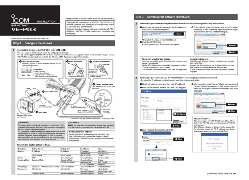
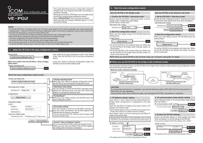
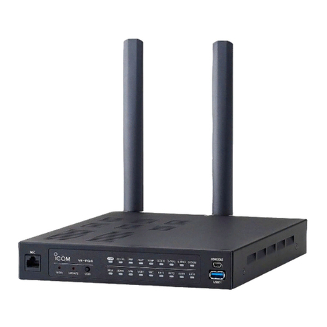
Icom VE-PG3 User manual

INTRODUCTION
Thank you for purchasing the VE-PG3. The VE-PG3 is a network converter that allows you to connect Icom
radios or repeaters to a VoIP network.
This guide describes the basic settings to operate the VE-PG3.
READ ALL INSTRUCTIONS carefully and completely before using.
i
The AMBE+2™ is a trademark of Digital Voice Systems, Inc.
Adobe and Reader are registered trademarks of Adobe Systems Incorporated in the United States and/or other countries.
Icom, Icom Inc. and the Icom logo are registered trademarks of Icom Incorporated (Japan) in Japan, the United States, the
United Kingdom, Germany, France, Spain, Russia and/or other countries.
All other products or brands are registered trademarks or trademarks of their respective holders.
ALL RIGHTS RESERVED. This document contains material protected under International and Domestic Copyright Laws
and Treaties. Any unauthorized reprint or use of this material is prohibited. No part of this document may be reproduced or
transmitted in any form or by any means, electronic or mechanical, including photocopying, recording, or by any information
storage and retrieval system without express written permission from Icom Incorporated.
All stated specifications and design are subject to change without notice or obligation.

INTRODUCTION
ii
1. This equipment complies with Part 68 of the FCC rules and the requirements adopted by the ACTA. On the
back of this equipment is a label that contains, among other information, a product identifier in the format
US:AAAEQ##TXXXX. If requested, this number must be provided to the telephone company.
2. The following USOC jacks may be used with this equipment: RJ11C.
3. A plug and jack used to connect this equipment to the premises wiring and telephone network must comply with the
applicable FCC Part 68 rules and requirements adopted by the ACTA. A compliant telephone cord and modular plug
is provided with this product. It is designed to be connected to a compatible modular jack that is also compliant. See
installation instructions for details.
4. The REN is used to determine the number of devices that may be connected to a telephone line.
Excessive RENs on a telephone line may result in the devices not ringing in response to an incoming call. In most
but not all areas, the sum of RENs should not exceed five (5.0). To be certain of the number of devices that may be
connected to a line, as determined by the total RENs, contact the local telephone company. For products approved
after July 23, 2001, the REN for this product is part of the product identifier that has the format US:AAAEQ##TXXXX.
The digits represented by ## are the REN without a decimal point (e.g., 03 is a REN of 0.3). For earlier products, the
REN is separately shown on the label.
5. If the equipment causes harm to the telephone network, the telephone company will notify you in advance that
temporary discontinuance of service may be required.
But if advance notice isn’t practical, the telephone company will notify the customer as soon as possible. Also, you
will be advised of your right to file a complaint with the FCC if you believe it is necessary.
6. The telephone company may make changes in its facilities, equipment, operations, or procedures that could affect
the operation of the equipment. If this happens, the telephone company will provide advance notice in order for you
to make the necessary modifications to maintain uninterrupted service.
If the equipment is causing harm to the telephone network, the telephone company may request that you disconnect
the equipment until the problem is resolved.
8. This equipment contains no user serviceable parts. Please contact to
Company Name: Icom America Inc.
Address: 2380 116th Ave NE Bellevue, WA 98004
Phone: (800) 426-7983
9. This equipment cannot be used on public coin service provided by the telephone company. Connection to Party
Line Service is subject to state tariffs. Contact the state Public Utility Commission, Public Service Commission, or
Corporate Commission for information.
10. If your home has specially wired alarm equipment connected to the telephone line, ensure the installation of this
MFP does not disable your alarm equipment. If you have questions about what will disable alarm equipment,
consult your telephone company or a qualified installer. FCC Telephone Consumer Protection Act The Telephone
Consumer Protection Act of 1991 makes it unlawful for any person to use a computer or other electronic device,
including FAX machines, to send any message unless such message clearly contains in a margin at the top
or bottom of each transmitted page or on the first page of the transmission, the date and time it is sent and an
identification of the business or other entity, or other individual sending the message, and the telephone number of
the sending machine or such business, other entity, or individual. The telephone number provided may not be a 900
number or any other number for which charges exceed local or long distance transmission charges.
To comply with this law, you must enter the following information in your fax unit:
• Date and time: see the Installation section of this document for instructions on doing this.
• Name and telephone number which identify the source of your fax transmission: see the User’s Handbook f for
instructions on doing this.
For USA

INTRODUCTION
iii
For Canada
This product meets the applicable Industry Canada technical specifications.
Le présent matériel est conforme aux specifications techniques applicables d’Industrie Canada.
The Ringer Equivalence Number (REN) is an indication of the maximum number of devices allowed to be connected
to a telephone interface. The termination of an interface may consist of any combination of devices subject only to the
requirement that the sum of the RENs of all the devices not exceed five.
L’indice d’équivalence de la sonnerie (IES) sert à indiquer le nombre maximal de terminaux qui peuvent être raccordés
à une interface téléphonique. La terminaison d’une interface peut consister en une combinaison quelconque de
dispositifs, à la seule condition que la somme d’indices d’équivalence de la sonnerie de tous les dispositifs n’excède
pas cinq.

1BEFORE USING THE VE-PG3
1-2
Panel description
MFront panel
<UPDATE> button ………… When [PWR/MSG] lights orange, a firmware update is ready.
• To use the Firmware Update function, an internet connection,
DNS and default gateway settings are necessary.
LED Indication In the Converter mode In the Bridge mode
PWR/MSG Doesn't light Power is OFF
Green Lights Power is ON
Blinks Booting
Red Lights –
Blinks –
Orange Lights A firmware update is ready./Downloading new firmware.
Blinks Accessing the USB flash drive.
(While loading the setting file or updating the firmware.)
Booting
Initialization is in progress. (Green and Orange LEDs alternately light.)
Firmware update is in progress.
WAN Doesn't light No network connection./Connecting to the network is in progress.
Green Lights Connected to the WAN line. (An IP address has been obtained.)
Blinks The WAN line is communicating.
Red Lights –
Blinks Authentication error/failed (PPPoE)
Failed to obtain IP address (DHCP) (Time-out timer: 30 seconds)
Orange Lights LAN port linkdown*
Blinks No PING reply from the specified host.*
V/RoIP Doesn't light No registration Not connected
Green Lights Registration succeed (All entries) Connected
Blinks The line is communicating. –
Red Lights –
Blinks 1 or more registrations failed. –
Orange Lights –
Blinks –
Front view
<UPDATE> button [WAN] LED [EXT] (1/2) LED
[PWR/MSG] LED [V/RolP] LED
[D-TRX] LED
[TRX] (1/2) LED [USB] port
(USB2.0)
*: Setting the [Abnormal Condition Monitoring] item on the [Expansion] screen is necessary for this indication, and the
LAN port linkdown monitoring takes priority. See page 5-102 and 5-103 for the details.

1BEFORE USING THE VE-PG3
1-3
Panel description
MFront panel (continued)
• All indicators light while updating the rmware or rebooting.
• The indication may differ, depending on the setting.
D-TRX* Doesn't light No transceiver is connected, or it is in the standby mode.
Green Lights Receiving an audio signal.
Blinks –
Red Lights Sending an audio signal.
Blinks –
Orange Lights The transceiver is communicating.
Blinks –
TRX1
TRX2
Doesn't light No transceiver is connected, or it is in the standby mode.
Green Lights Receiving an audio signal.
Blinks –
Red Lights Sending an audio signal.
Blinks –
Orange Lights The transceiver is communicating.
Blinks –
EXT1
EXT2
Doesn't light No input or output signal.
Green Lights Input is busy.
Blinks –
Red Lights Output is busy.
Blinks –
Orange Lights Input or output is busy.
Blinks –
*For the operation using an IC-FR5000/FR6000.
Front view
<UPDATE> button [WAN] LED [EXT] (1/2) LED
[PWR/MSG] LED [V/RolP] LED
[D-TRX] LED
[TRX] (1/2) LED [USB] port
(USB2.0)

1BEFORE USING THE VE-PG3
1-4
Panel description
MFront panel (continued)
[USB] ports ………………… CAUTION: Turn OFF the power before connect or disconnect the USB flash
drive.
[Connecting a USB flash drive]
The configuration and firmware can be transferred using a USB flash drive
(purchase separately).
• Only one USB flash drive can be accepted at a time.
[Connecting the CT-24]
Connect the optional CT-24 to communicate with IC-FR5000/FR6000.
• The VE-PG3 accepts up to two CT-24s.
• When you want to connect two CT-24s and USB flash drive, a USB HUB
(self-powered HUB) is required.
Connect one CT-24 and the USB flash drive to the USB port, and connect
the other CT-24 to the USB HUB.
CT-24
USB cable
(Supplied with CT-24)
Tu rn OFF the power and
then connect the USB
cable
Cushion sheet
(Supplied with CT-24)
Cushion
NOTE:
NEVER use a USB cable other
than supplied with the CT-24.
Lights Green: Connected to the VE-PG3
Lights Orange: Communicating
LED
LED indication:
Front view
<UPDATE> button [WAN] LED [EXT] (1/2) LED
[PWR/MSG] LED [V/RolP] LED
[D-TRX] LED
[TRX] (1/2) LED [USB] port
(USB2.0)

1BEFORE USING THE VE-PG3
1-5
Panel description (continued)
MRear panel
wqtyer ui
PHONE LINE2LINE1
q[TRX](1/2) port …………… Connect the transceiver through the optional cable.
w[EXT](1/2) port …………… Connect the external equipment through the optional cable.
e[PHONE] port …………… Connect a telephone.
r[LINE](1/2) ports ………… Connect to the PSTN.
t[WAN] port………………… Connect the network terminal device.
• The router function is disabled as the default setting.
Configure the network setting (DHCP Client/Static IP/PPPoE) according to
your network service provider.
y[LAN] port ………………… Connect the network device such as a HUB.
uDC jack …………………… Connect the supplied AC adaptor.
iGround terminal ………… Connect the ground wire.
ABOUT THE OPTIONAL CONNECTION CABLE
Before connecting cables, see the cable's manual and the
sticker on the bottom of the VE-PG3 for port information.
• Verify that both the VE-PG3 and connected devices are
turned OFF when connecting or disconnecting the cable.
• Hold the connector body when connecting or disconnecting
them.
• When other cables are connected, you can use needle-nose
pliers to carefully insert or remove connectors.
• Never bend or pinch the cable.
• Never place a heavy object on the cable.
• Never touch the cable with wet hands.
• Always connect the cable correctly. An incorrect connection
could damage the VE-PG3 and/or the transceiver.
VE-PG3(bottom view)
Connection cable(optional)
Port information on the sticker
Sticker
A
B

1BEFORE USING THE VE-PG3
1-6
Panel description (continued)
MBottom panel
<INIT> button
<INIT> button ……………… If you cannot access to the VE-PG3 setting screen, you can initialize the
VE-PG3.
• See the "PRECAUTIONS" leaflet for the detail.
• Initializing clears all the settings.

2-1
BRIDGE MODE APPLICATION Section 2
NOTE:
In this guide, the descriptions assume that all configurations of the PC and VE-PG3's IP address have been completed.
1. Operation in the Multicast mode …………………………………………………………………………………………… 2-2
1. Configuration ……………………………………………………………………………………………………………… 2-2
2. Connection ………………………………………………………………………………………………………………… 2-3
3. Operation …………………………………………………………………………………………………………………… 2-4
2. Operation in the Unicast mode ……………………………………………………………………………………………… 2-5
1. Configuration ……………………………………………………………………………………………………………… 2-5
2. Connection ………………………………………………………………………………………………………………… 2-6
3. Operation …………………………………………………………………………………………………………………… 2-7
3. Using the Mixing function …………………………………………………………………………………………………… 2-8
1. Configuration ……………………………………………………………………………………………………………… 2-8
2. Connection ………………………………………………………………………………………………………………… 2-9
3. Operation ………………………………………………………………………………………………………………… 2-10
4. Operating in the NXDN Conventional mode …………………………………………………………………………… 2-11
1. UC-FR5000 configuration ……………………………………………………………………………………………… 2-11
2. VE-PG3 configuration…………………………………………………………………………………………………… 2-12
3. Connection ……………………………………………………………………………………………………………… 2-13
4. Operation ………………………………………………………………………………………………………………… 2-14

2BRIDGE MODE APPLICATION
2-2
1. Operation in the Multicast mode
In the Multicast mode, a call from one site can be sent to multiple sites.
• In the instruction, the example of the communication as illustrated below, is used.
Area AArea B
An example of Multicast mode
Radio A
Radio A1 Radio B1
VE-PG3
(192.168.0.3)
VE-PG3
(192.168.0.2)
[TRX1] [LAN][LAN]
[TRX1]
Radio B
1. Configuration
Access the VE-PG3 setting screen, and set the items as shown below.
Menu Item Setting Screen Setting Item Item Name Value
Operating Mode Operating Mode Operating Mode Operating Mode Bridge
IP Communication Mode IP Communication Mode Multicast
Port Settings Transceiver 1 (TRX1) Transceiver Model: Transceiver Model IC-F5060/F6060
VE-PG3 (Area A/B)

2BRIDGE MODE APPLICATION
2-3
2. Connection
Set the transceiver channel, volume level, TX output power, and other necessary settings, before connecting to the
VE-PG3.
Connect the VE-PG3 and the transceiver, using the appropriate optional cable.
• Verify that both the VE-PG3 and the transceiver are turned OFF when connecting the cable.
1
When all the connections are finished, turn ON the transceiver and VE-PG3’s power.
2
VE-PG3 (Rear view) Icom’s transceiver
(IC-F5060/IC-F6060 series) (Rear view)
(Front view)
To the external speaker jack
To the microphone connector
LINE2 LINE1
PHONE
• The [TRX1] and [TRX2] ports (upper slots) accept the OPC-2275 connectors,
however, follow the example to correctly connect the transceiver to ONLY the [TRX1] on the VE-PG3.
ABC
Be sure to insert the
connectors top side up.
Bottom
To p
A
1234
OPC-2275
AABC
To [TRX1] (Upper slots)
1. Operation in the Multicast mode (continued)
NOTE:
• Verify that both the radio and the VE-PG3 are turned OFF when connecting or disconnecting the transceiver.
• Keep the radio away from a PC, AC adaptor and other electronic equipment. The noise emitted from those equipment may
interfere with the radio.
• When operating the radio, do not transmit near the IP telephone.

2BRIDGE MODE APPLICATION
2-4
1. Operation in the Multicast mode (continued)
3. Operation
• Radio A1 and B1 can normally communicate as if they are directly communicating in the simplex mode.
• All radios in the area must have same setting.
Area AArea B
An example of Multicast mode
Radio A
Radio A1 Radio B1
VE-PG3
(192.168.0.3)
VE-PG3
(192.168.0.2)
[TRX1] [LAN][LAN]
[TRX1]
Radio B

2BRIDGE MODE APPLICATION
2-5
2. Operation in the Unicast mode
In the Unicast mode, you can call the designated radio, using a communication port.
• In the instruction, the example of the communication as illustrated below, is used.
Area AArea B
An example of communication the Unicast mode
Radio A Radio B
Radio A1 Radio B1
VE-PG3
(192.168.0.3)
VE-PG3
(192.168.0.2)
[TRX1]
[LAN][LAN]
[TRX1]
*Enter the IP address of VE-PG3 in area A (ex. 192.168.0.2) for the VE-PG3 in area B.
**Click [Connect], and verify that "During transmit" is displayed.
Menu Item Setting Screen Setting Item Item Name Value
Operating Mode Operating Mode Operating Mode Operating Mode Bridge
IP Communication Mode IP Communication Mode Unicast
Port Settings Transceiver 1 (TRX1) Transceiver Model Transceiver Model IC-F5060
Bridge Connection Bridge Connection Bridge Connection Point Connection IP Address* 192.168.0.3
Connection Port Number 21500
My Station Port Number 21500
List of Bridge Connection Point Entries
Connection Status** "During transmit"
VE-PG3 (Area A)
1. Configuration
Access the VE-PG3 setting screen, and set the items as shown below.
Click

2BRIDGE MODE APPLICATION
2-6
1
2
VE-PG3 (Rear view) Icom’s transceiver
(IC-F5060/IC-F6060 series) (Rear view)
(Front view)
To the external speaker jack
To the microphone connector
LINE2 LINE1
PHONE
• The [TRX1] and [TRX2] ports (upper slots) accept the OPC-2275 connectors,
however, follow the example to correctly connect the transceiver to ONLY the [TRX1] on the VE-PG3.
ABC
Be sure to insert the
connectors top side up.
Bottom
To p
A
1234
OPC-2275
AABC
To [TRX1] (Upper slots)
2. Operation in the Unicast mode (continued)
NOTE:
• Verify that both the radio and the VE-PG3 are turned OFF when connecting or disconnecting the transceiver.
• Keep the radio away from a PC, AC adaptor and other electronic equipment. The noise emitted from those equipment may
interfere with the radio.
• When operating the radio, do not transmit near the IP telephone.
2. Connection
Set the transceiver channel, volume level, TX output power, and other necessary settings, before connecting to the
VE-PG3.
When all the connections are finished, turn ON the transceiver and VE-PG3’s power.
Connect the VE-PG3 and the transceiver, using the appropriate optional cable.
• Verify that both the VE-PG3 and the transceiver are turned OFF when connecting the cable.

2BRIDGE MODE APPLICATION
2-7
2. Operation in the Unicast mode (continued)
• All radios in the area must have same setting.
3. Operation
• Radio A1 and B1 can normally communicate as if they are directly communicating in the simplex mode.
Area AArea B
An example of communication the Unicast mode
Radio A Radio B
Radio A1 Radio B1
VE-PG3
(192.168.0.3)
VE-PG3
(192.168.0.2)
[TRX1]
[LAN][LAN]
[TRX1]

2BRIDGE MODE APPLICATION
2-8
3. Using the Mixing function
The mixing function mixes conversations from different Areas. As shown in the figure below, the Area A radio users
can talk to the Area B and relayed to the Area C.
• In this example, the audio signal of [TRX1] port and [TRX2] port (VE-PG3 in Area B) are mixed as illustrated
below.
Menu Item Setting Screen Setting Item Item Name Value
Operating Mode Operating Mode Operating Mode Operating Mode Bridge
IP Communication Mode IP Communication Mode Unicast
Mixing Group* Transceiver 1(TRX1),
Transceiver2(TRX2)
Port Settings Transceiver 1 (TRX1) Transceiver Model: Transceiver Model IC-F5060/F6060
Transceiver 2 (TRX2) Transceiver Model: Transceiver Model IC-F5060/F6060
Bridge Connection Bridge Connection Point Bridge Connection Point Connection IP Address TRX1:192.168.0.2
TRX2:192.168.0.4
List of Bridge Connection
Point Entries
Connection Status During Transmit
Area A Area B
An example of communication with the Mixing function
Radio A1 Radio C1
Radio B1
VE-PG3
(192.168.0.2)
[TRX1]
[LAN] [LAN]
Area C
VE-PG3
(192.168.0.4)
[TRX2]
Radio D1
Radio A Radio C
Unicast Unicast
IP
Network
Radio B
[TRX1]
Radio D
[TRX2]
VE-PG3
(192.168.0.3)
Mixing
Mixing
VE-PG3 (Area B)
1. Configuration
Access the VE-PG3 setting screen, and set the items as shown below.
• Configure the VE-PG3 in Area A and C, referring to “Operation in the Unicast mode.“
*Enter the round marks to the “Group1” field in the Transceiver 1 (TRX1) and Transceiver 2 (TRX2) rows.

2BRIDGE MODE APPLICATION
2-9
1
2
VE-PG3 (Rear view) Icom’s transceiver
(IC-F5060/IC-F6060 series) (Rear view)
(Front view)
To the external speaker jack
To the microphone connector
LINE2 LINE1
PHONE
• The [TRX1] and [TRX2] ports (upper slots) accept the OPC-2275 connectors,
however, follow the example to correctly connect the transceiver to ONLY the [TRX1] on the VE-PG3.
ABC
Be sure to insert the
connectors top side up.
Bottom
To p
A
1234
OPC-2275
AABC
To [TRX1] (Upper slots)
3. Using the Mixing function (continued)
2. Connection
Set the transceiver channel, volume level, TX output power, and other necessary settings, before connecting to the
VE-PG3.
Connect the VE-PG3 and the transceiver, using the appropriate optional cable.
• Verify that both the VE-PG3 and the transceiver are turned OFF when connecting the cable.
When all the connections are finished, turn ON the transceiver and VE-PG3’s power.
NOTE:
• Verify that both the radio and the VE-PG3 are turned OFF when connecting or disconnecting the transceiver.
• Keep the radio away from a PC, AC adaptor and other electronic equipment. The noise emitted from those equipment may
interfere with the radio.
• When operating the radio, do not transmit near the IP telephone.
•Only Voice Codec G.711u can be used with the Mixing function.

2BRIDGE MODE APPLICATION
2-10
3. Using the Mixing function (continued)
3. Operation
• All radios in the area must have same setting.
• Radio A1 and B1 can normally communicate as if they are directly communicating in the simplex mode.
• The conversations from different Areas can be heard.
• While other radios are transmitting, you cannot transmit.
Area A Area B
An example of communication with the Mixing function
Radio A1 Radio C1
Radio B1
VE-PG3
(192.168.0.2)
[TRX1]
[LAN] [LAN]
Area C
VE-PG3
(192.168.0.4)
[TRX2]
Radio D1
Radio A Radio C
Unicast Unicast
IP
Network
Radio B
[TRX1]
Radio D
[TRX2]
VE-PG3
(192.168.0.3)
Mixing
Mixing
Other manuals for VE-PG3
3
Table of contents
Other Icom Gateway manuals
Popular Gateway manuals by other brands

HomeMatic
HomeMatic HM-LGW-O-TW-W-EU Installation and operating manual

Silex technology
Silex technology BR-310AC user guide

ABB
ABB ARG600 Dual SIM user manual

HMS Networks
HMS Networks Ixxat SG-gateway user manual

RTA
RTA 460MCWI-N2E Product user guide

Grandstream Networks
Grandstream Networks GXW42XX series user manual

Johnson Controls
Johnson Controls Simplicity LINC Application guide

hilscher
hilscher netTAP NT 151-RE-RE user manual

2-Wire
2-Wire 2710HGV-TNZ user manual

Leuze electronic
Leuze electronic MA 258i operating instructions

ZyXEL Communications
ZyXEL Communications P-660H Series user guide

SMC Networks
SMC Networks EZ Connect SMC8014WG-SI install guide