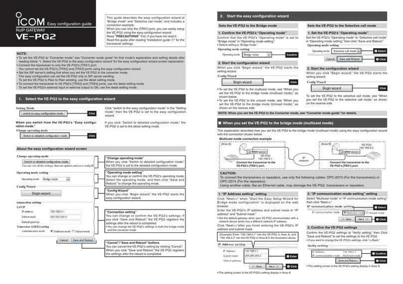
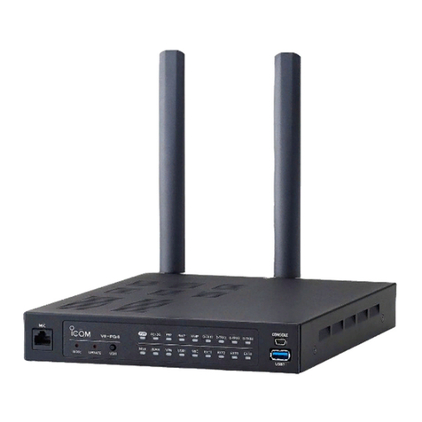
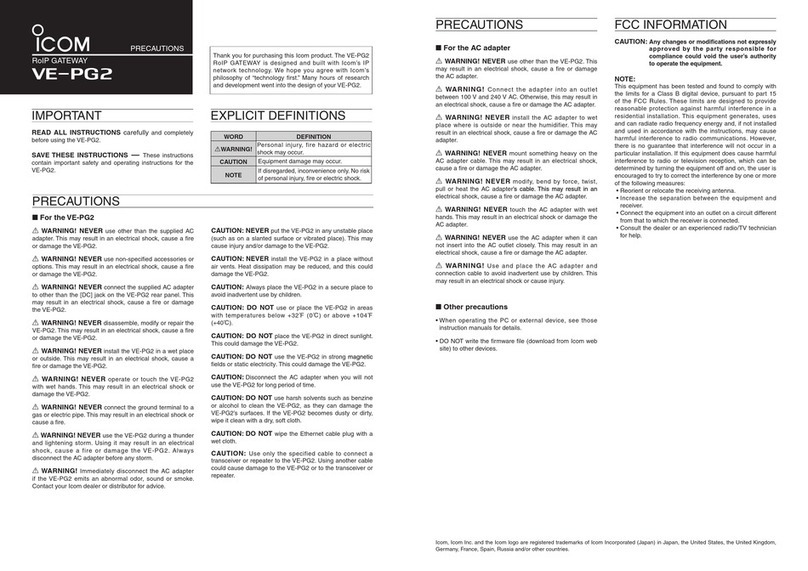
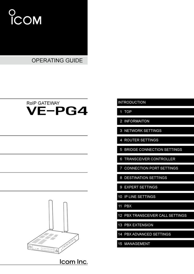
Icom VE-PG4 User manual

INTRODUCTION
1 BEFORE USING THE IP1000C
2 SETTING UP THE IP1000C SYSTEM
3 OTHER BASIC FUNCTIONS
4 ABOUT THE SETTING SCREEN
5 MAINTENANCE
6 FOR YOUR INFORMATION
INTRODUCTION
1. BEFORE USING THE VE-PG4
2. SETTING UP THE TRANSCEIVERS
3. WIRELESS LAN TRANSCEIVERS
4. CONFIGURING THE PBX SYSTEM
5. MAINTENANCE
6. FOR YOUR INFORMATION
INSTALLATION GUIDE
RoIP GATEWAY
VE-PG4

i
INTRODUCTION
Thank you for choosing this Icom product.
The VE-PG4 RoIP GATEWAY is designed and built with Icom’s IP network technology.
We hope you agree with Icom’s philosophy of “technology rst.” Many hours of research and development
went into the design of your VE-PG4.
ALL RIGHTS RESERVED. This document contains material protected under International and Domestic
Copyright Laws and Treaties. Any unauthorized reprint or use of this material is prohibited. No part of
this document may be reproduced or transmitted in any form or by any means, electronic or mechanical,
including photocopying, recording, or by any information storage and retrieval system without express written
permission from Icom Incorporated.
All stated specications and design are subject to change without notice or obligation.
Icom, Icom Inc. and the Icom logo are registered trademarks of Icom Incorporated (Japan) in Japan, the
United States, the United Kingdom, Germany, France, Spain, Russia, Australia, New Zealand, and/or other
countries.
Microsoft and Windows are registered trademarks of Microsoft Corporation in the United States and/or other
countries.
AMBE+2 is a trademark and property of Digital Voice Systems Inc.
All other products or brands are registered trademarks or trademarks of their respective holders.
Icom is not responsible for the destruction, damage to, or performance of any Icom or non-Icom equipment,
if the malfunction is because of:
• Force majeure, including, but not limited to, res, earthquakes, storms, oods, lightning, other natural
disasters, disturbances, riots, war, or radioactive contamination.
• The use of Icom transceivers with any equipment that is not manufactured or approved by Icom.
Voice coding technology
The AMBE+2™ voice coding Technology embodied in this product is protected by intellectual property
rights including patent rights, copyrights and trade secrets of Digital Voice Systems, Inc. This voice coding
Technology is licensed solely for use within this Communications Equipment.
The user of this Technology is explicitly prohibited from attempting to extract, remove, decompile, reverse
engineer, or disassemble the Object Code, or in any other way convert the Object Code into a human-
readable form. U.S. Patent Nos.
#8,595,002, #8,359,197, #8,315,860, #8,200,497, #7,970,606, and #6,912,495 B2.

ii
INTRODUCTION
Features
• The VE-PG4 RoIP Gateway enables you to communicate between transceivers, wireless LAN transceivers
or IP telephones, that are connected to the RoIP Gateway, through IP networks.
Controls IP transceivers and wireless LAN transceivers through a 4G/3G line.
LPanasonic KX series IP telephones are usable, as of April, 2019.
LThe 3G/4G line is required to connect to the IP transceiver controller.
LA total of up to 50 wireless LAN transceivers and IP100FSs remote communicator, and up to 25 IP telephones can
be registered and used in the VE-PG4 system.
• Connects to speakers in the system,
• Enables emergency calls to linked transceivers and speakers, and monitors unusual operation of the linked
transceivers.
• A USB ash drive can be connected to the USB port for such as recording the audio communication between
transceivers and telephones, updating the rmware and backing up or restoring the settings.
• Supports SNMP for network management.
• IP ltering function that restricts access from unknown network addresses.
• Automatic switching between 10BASE-T, 100BASE-TX, and 1000BASE-T.
LThis document is described based on the VE-PG4 rmware version 1.03.
Supported Icom radio products (As of April, 2019)
The following Icom transceivers can be connected to a VE-PG4.
LSome models may not be available in some countries. Ask your dealer for details.
Category Model Description
in this manual Mode Connected to Cable (optional)
Marine IC-M604A/
IC-M605 series
IC-M604
IC-M605 Analog [EXT] (EXT I/O) OPC-2273
Land IC-F5060 series/
IC-F6060 series IC-F5060/F6060 Analog [EXT] (EXT I/O) OPC-2275
Aviation IC-A120 series IC-A120 Analog [EXT] (EXT I/O) OPC-2275
Repeater IC-FR5000 series/
IC-FR6000 series
IC-FR5000/
FR6000 Analog [EXT] (EXT I/O) OPC-2390
NXDN Type-D/
dPMR Mode 2 [LAN]* LAN (User supplied)
*The optional UC-FR5000 must be installed.

iii
INTRODUCTION
• RC-FS10
remote communicator
to create a virtual radio or
simple dispatcher on a PC.
LNecessary to communicate with
an Icom repeater.
Options (As of April, 2019)
• OPC-2273 connection cable
for the IC-M604A/M605
(Length: Approximately
5m/16.4 ft)
• OPC-2275 connection cable
for the IC-F5060/F6060 and
IC-A120/E
(Length: Approximately
5m/16.4 ft)
• OPC-2276 connection cable
for the Icom microphone and
speaker
(Length: Approximately
5m/16.4 ft)
• CT-24*1digital voice converter
to communicate using
AMBE+2™ codec.
• SM-26 desktop microphone
to make a call on the VE-
PG4.*2
• HM-152 microphone
to make a call on the VE-
PG4.*2
• HM-241 speaker microphone
(Future product)
to directly make a call on the
VE-PG4.
• OPC-2389 connection cable
for the Icom serial
communication device
(Length: Approximately
5m/16.4 ft)
• OPC-2390 connection cable
for the IC-FR5000/FR6000
(Length: Approximately
5m/16.4 ft)
*1The VE-PG4 has 4 internal AMBE+2 Vocoder corresponding to the CT-24. When you need more than 5 AMBE+2
Vocoder you can add up to 2 CT-24s to the RoIP Gateway, according to the combination of the connected devices or
using voice protocol.
Refer to the Section 5 in the Operating guide.
*2
An optional OPC-2276 connnection cable is required.

iv
INTRODUCTION
Menu Item Screen Setting Item Option Value
Network Settings IP Address IP Address IP Address 192.168.0.1
Subnet Mask 255.255.255.0
DHCP Server DHCP Server DHCP Server Disable
Router Settings WAN Connection Type Connection Type LAN Port
Connection Port
Settings
EXT I/O (EXT) EXT I/O Port Mode Connected Unit Transceiver (EXT 1/2)
EXT I/O Unit (EXT 3/4)
EXT I/O EXT I/O Port EXT I/O 1 (EXT 1)
Transceiver Model Transceiver Model IC-F5060/F6060
Management Administrator Administrator Password Username admin (xed)
Current Password: admin (lower case)
Network and system default settings
LSee the Operating guide for more details on above settings.
LThe Administrator’s Username (admin) cannot be changed.
To prevent unauthorized access
• You must choose a strong password and change it occasionally.
• Choose one that is not easy to guess.
• Use numbers, characters and letters (both lower and upper case).
Conrming the MAC address
The MAC address of the built-in WAN or LAN module of the VE-PG4 is shown on the Serial label at the
bottom of the product.
LYou can also check the MAC address on the setting screen. See the Operating guide for details.
The contents of the serial label may vary,
depending on the version.
Serial label
VE-PG4 (Bottom)
0090C7
0090C7
MAC address for LANMAC address for LAN
MAC address for WANMAC address for WAN

v
INTRODUCTION
ABOUT THE CONSTRUCTION OF THE MANUAL
You can use the following manuals to understand and operate this RoIP Gateway.
Precautions (Comes with the RoIP Gateway)
Instructions for the connections, initialization, and precautions.
Installation guide (This manual, PDF type)
Instructions for the system requirements, the system setup basics, maintenance, and the specications.
It can be downloaded from the Icom website.
Operating guide (PDF type)
The detailed references for the settings in the RoIP Gateway setting screen.
It can be downloaded from the Icom website.

1-1
Section
BEFORE USING THE VE-PG4 1
Panel description ……………………………………………………………………………………………………… 1-2
MFront panel ……………………………………………………………………………………………………… 1-2
MRear panel ……………………………………………………………………………………………………… 1-6
MSide and bottom panels ………………………………………………………………………………………… 1-8
Feature description …………………………………………………………………………………………………… 1-9
MExpanding communication coverage ………………………………………………………………………… 1-9
MCommunication between a VoIP telephone and a transceiver …………………………………………… 1-9
MControlling wireless LAN transceivers ……………………………………………………………………… 1-10
MConnecting to the IP transceiver controllers ……………………………………………………………… 1-12
MThe router function …………………………………………………………………………………………… 1-12
MThe VPN function …………………………………………………………………………………………… 1-12
MAudio recorder function ……………………………………………………………………………………… 1-12
MVirtual serial port ……………………………………………………………………………………………… 1-12
Installation and connections ……………………………………………………………………………………… 1-13
MAttaching the magnet legs …………………………………………………………………………………… 1-13
MAttaching the antennas ……………………………………………………………………………………… 1-14
MSetting a static IP address to a PC ………………………………………………………………………… 1-15
MConnecting the cables and the PC ………………………………………………………………………… 1-16
The setting screen ………………………………………………………………………………………………… 1-17
MAccessing the setting screen………………………………………………………………………………… 1-17
MSetting screen description …………………………………………………………………………………… 1-18
MChanging the IP address on the setting screen …………………………………………………………… 1-19

1BEFORE USING THE VE-PG4
1-2
■Front panel
Panel description
INDICATORS
1[PWR] ��������� Lights green: Power is ON
Blinks green: Booting up
Blinks red: UID indication
Not lit: Power is OFF
2[4G/3G] ��������� Lights green: RSSI level 2 or more in the 4G mode
Blinks green: RSSI level 0 ~ 1 in the 4G mode
Lights red: RSSI level 2 or more in the 3G mode
Blinks red: RSSI level 0 ~ 1 in the 3G mode
Not lit: Out of the service range, or the SIM card is not
attached
3[PPP] ���������� Lights green: Authenticated to a 4G or 3G line
Not lit: Condition other than the above
4[RoIP] ��������� Lights green: In audio/data communication with IP transceivers
(Receive)
Lights orange: In audio/data communication with IP transceivers
(Full duplex)
Lights red: In audio/data communication with IP transceivers
(Transmit)
Not lit: Condition other than the above
5[VoIP]���������� Lights green: Registration succeed (All entries)
Blinks green: 1 or more phone lines are communicating
Blinks red: 1 or more registrations failed
Not lit: No registration/Connecting
6[D-TRX1] ~ [D-TRX4] ��� Lights green: In the communication with digital transceivers.
(Receive)
Lights orange: In the communication with digital transceivers.
(Full duplex)
Lights red: In the communication with digital transceivers
(Transmit)
Not lit: Condition other than the above
1
89
2345 6 7

1BEFORE USING THE VE-PG4
1-3
Panel description
■Front panel
7[CONSOLE] PORT
(USB 2.0/1.1) ������ Connect a USB (mini B type) cable (user supplied) to remotely
configure the VE-PG4 from a PC using a terminal software (user
supplied.)
About the USB driver
To use the [CONSOLE] port, the USB driver for the Icom network
devices is required.
Download it from the Icom website and install it on your PC.
http://www.icom.co.jp/world/support/
8[USB1] PORT
(USB 3.0) �������� Connect a USB flash drive (user supplied) to save or restore settings or
to update the firmware.
LYou can save the recorded audio on a data storage device through the USB
port. Only one storage device can be connected to the USB port at a time.
LBe sure to back up the data on the USB ash drive before connecting it to
the VE-PG4.
LA USB ash drive, such as one with biometric authentication, or one with
password protection is not supported.
LSome USB devices may not be usable with the VE-PG4.
LThe VE-PG4 accepts up to two CT-24s for optional AMBE+2 vocorders.
1
89
2345 6 7

1BEFORE USING THE VE-PG4
1-4
Panel description
■Front panel
1
89
2345 6 7
INDICATORS
9[EXT1] ~ [EXT4] ����� Lights green: Receiving an audio signal.
Lights orange: In audio/data communication with transceivers (Full
duplex).
Lights red: In audio/data communication with transceivers
(Receive).
Not lit: Condition other than the above.
[MIC] ���������� Lights green: Receiving an audio signal through [MIC].
Lights orange: Communicating through [MIC] (Full duplex).
Lights red: Sending an audio signal through [MIC].
[USB1] ��������� Lights green: A USB flash drive is connected.
Blinks green: Accessing the USB flash drive.
Lights red: Failed loading a firmware or backup data from the
USB flash drive.
Not lit: Condition other than the above.
[VPN] ���������� Lights green: At least one IPsec tunnel has been established.
Not lit: Not connected./VPN not used./Invalid setting.
[WAN] ��������� Lights green: Connected to the WAN line.
Authentication succeeded (PPPoE)
Succeed to obtain IP address (DHCP client)
Blinks red: Authentication error/failed (PPPoE)
Failed to obtain IP address (DHCP client)
Not lit: Condition other than the above.
[MSG] ��������� Lights green: A firmware update is ready.
Blinks green: Initialization is in progress./Firmware update is in
progress.
Not lit: Condition other than the above.

1BEFORE USING THE VE-PG4
1-5
Panel description
■Front panel
1
89
2345 6 7
<USB1> BUTTON ���� When removing the USB flash drive, hold down this button until
[USB1] () turns OFF.
<UPDATE> BUTTON ��� When [MSG] lights green, a firmware update is ready. Hold down this
button until [MSG] blinks green to update the firmware.
LWhen you do not use the 4G or 3G line, an internet connection is necessary
for the rmware update through the network.
LUse a pin to push the button.
<MODE> BUTTON ���� Push to initialize the settings. See Section 5 for details.
LUse a pin to push the button.
[MIC] PORT ������� Connect to the optional speaker-microphone.
Insert the speaker-microphone connector until it clicks.
LTurn OFF the VE-PG4 before connecting or disconnecting the speaker-
microphone.
LNever connect a LAN cable to the [MIC] port.
LThe [MIC] and [EXT1] ports cannot be used at the same time.
While a speaker-microphone is connected, audio input to or output from the
[EXT1] port on the rear panel is muted.

1BEFORE USING THE VE-PG4
1-6
■Rear panel
Panel description
1[ANT1]/[ANT2]
CONNECTORS ����� Attach antennas to communicate with IP transceivers through the
4G/3G line. Always attach two antennas. (p.1-14)
[ANT1] is also used for the GPS function.
2[LAN] PORT
(RJ-45 type) ������� Connect a network device such as a Switch.
Lights: Connected
Blinks: Communicating
qgreen:1000BASE-T
w orange: 10BASE-T/100BASE-TX
qw
3[WAN/LAN] PORT
(RJ-45 type) ������� Connect a proper device, depending on the Line Type setting.
(Router Settings > WAN > Connection Type)
See the Operating guide for details.
• Used as a LAN port (default)
Connect a network device such as a Switch or Router modem.
• DHCP Client, Static IP, or PPPoE
Connect a bridge modem (ADSL, VDSL or CATV) or FTTH terminal.
Lights: Connected
Blinks: Communicating
qGreen: 1000BASE-T
wOrange: 10BASE-T/100BASE-TX
qw
4[GND] TERMINAL ���� Connect to ground.
5[DC] JACK ������� Connect the supplied power adapter.
A1~A4A1~A4 B1~B4B1~B4 C1~C4C1~C4
1
45678
2 3 1

1BEFORE USING THE VE-PG4
1-7
Panel description
■Rear panel
A1~A4A1~A4 B1~B4B1~B4 C1~C4C1~C4
1
45678
2 3 1
6[USB2]/[USB3] PORTS
(USB3.0) �������� Connect a USB flash drive (user supplied) to restore the settings or to
update the firmware.
LYou can save the recorded audio on a data storage device through the USB
port. Only one storage device can be connected to the USB port at a time.
LBe sure to back up the data on the USB ash drive before connecting it to
the VE-PG4.
LA USB ash drive such as one with biometric authentication, or one with
password protection, is not supported.
LSome USB devices may not be usable with the VE-PG4.
LThe VE-PG4 accepts up to two CT-24s for optional AMBE+2 vocoder.
7<USB2/3> BUTTON ��� Before removing the USB flash drive, hold down this button until the
indicator below the button turns OFF.
8[EXT1] ~ [EXT4] PORTS � Connect external devices or transceivers.
LBe sure that both the VE-PG4 and the connected devices or transceivers are
turned OFF when connecting or disconnecting the cables.
LThe default settings for the [EXT] ports are:
[EXT1] / [EXT2]: To connect to a transceiver
[EXT3] / [EXT4]: To connect to an external I/O port
See the Section 6 for details on the [EXT] ports.

1BEFORE USING THE VE-PG4
1-8
Panel description
■Side and bottom panels
1
2
1Security slot ������ Attach a security wire (user supplied).
Refer to the instruction manual that comes with the security wire for
details.
2SIM card slot ������ Install the SIM card. Ask your dealer for installation or removal.

1BEFORE USING THE VE-PG4
1-9
■Expanding communication coverage
You can communicate with Icom transceivers* through the communication port.
*Only the Icom recommended transceivers.
Feature description
[D-TRX1] [LAN]
IP Phone
KX series
VoIP telephone
Icom transceiver
(SU)
Icom repeater
SIP server
VE-PG4
P
0
P
1
P
2
P
3
P
4
Icom transceiver
(SU)
Icom
transceiver
Icom
transceiver
[EXT1] [EXT1]
[EXT2]
VE-PG4 VE-PG4
Icom transceiver
(SU)
IP Network
■Communication between a VoIP telephone and a transceiver
• Up to 25 IP phones can be congured/registered as extensions.
• You can communicate between IP phone and a transceiver.
You can call a designated transceiver from the IP phone.

1BEFORE USING THE VE-PG4
1-10
Feature description
■Controlling wireless LAN transceivers
You can communicate through IP networks using the VE-PG4 as a controller for up to 50 wireless LAN
transceivers.
LA wireless access point is required.
LThe IP100H and IP100FS are usable, as of April, 2019.
Simplex and Full-Duplex communication
The VE-PG4 has two methods of communication, Simplex and Full-Duplex.
Simplex is for communications where receive and transmit are done alternately one by one, and Full-Duplex is
for simultaneous receive and transmit just like a telephone call.
Set the Communication Method in “Transceiver Settings” for each IP communication terminal registered to the
VE-PG4.
LYou have to connect an optional microphone to the IP100H to make Full-Duplex communications. You can
communicate in the Simplex mode with no external microphone is connected.
All Call and Group Call
Simplex or Full-Duplex communication can be set for All Calls and Group Calls.
Enter a group on the Destination Setting screen, and then set a Group ID to each Wireless LAN transceiver to
join a Group.
(Destination Settings > Destination Settings)
Area Call
To use Area Call, you must enable the [Area Call] for each IP100H on the Transceiver Settings screen, and
then register the area’s wireless access point (BSSID).
( Transceiver Controller > Transceiver Settings > Transceiver Settings > Function Settings > Area Call)
( Transceiver Controller > RoIP Server Settings > Area Call > Area Entry List)
[LAN]
VE-PG4
Icom
Access point
(Example: AP-95M)
IP100FS
(Remote communicator)
IP100H
(Wireless LAN transceiver)

1BEFORE USING THE VE-PG4
1-11
Feature description
■Controlling wireless LAN transceivers
Talkgroup
The Talkgroup Call function enables wireless LAN transceivers and IP transceivers to select the group that
belong to it from previously registered groups in the VE-PG4.
When users select Talkgroup 1000, terminals are excluded from the original groups, as illustrated below.
• Talkgroup Calls require registering the Talkgroups in the [Destination Settings] screen and [ID List] screen. If the
“Talkgroup Type” in the [Destination Settings] screen is set to “Multiplex Talkgroup,” a IP100H can make a Talkgroup Call
between the linked Talkgroups.
(Transceiver Controller > Common Settings > ID List)
(Destination Settings > Destination Settings > Destination Settings > Talkgroup Type*)
*Displayed only when [Call Type] is set to “Talkgroup.”
• Set to the VE-PG4 whether All Call includes the Talkgroup or not, or the Talkgroup Call calls the IP100FS or not.
• The ID List and the destination settings set in the VE-PG4 are commonly used in each group that the IP100H and
IP100FS belong to.
Group 0100
All
Group 0101
Talkgroup 1000
When Talkgroup is OFF
Talkgroup 1001
0001 0002 0003 0004 0006 0007 0008 0009
Group 0100
All
Group 0101
Talkgroup 1000
When Talkgroup is selected
Talkgroup 1001
0001 0002 0003 0007 0008
0004
0006
0009

1BEFORE USING THE VE-PG4
1-12
Feature description
■Connecting to the IP transceiver controllers
You can communicate between IP transceivers, wireless LAN transceivers, and conventional transceivers.
LWhen communicating through a 4G or 3G line, attach both antennas for the maximum performance.
■The router function
When the router function of the VE-PG4 is enabled, the devices such as PCs that are connected to the
VE-PG4 can access the internet.
LThe Routing function is disabled as the default.
LAsk your Internet service provider (ISP) for the network line type.
■The VPN function
VPN (Virtual Private Network) enables a host computer to send and receive data across shared or public
networks like the Internet as if it were a private network.
LCongure the VPN connection using the IPsec. (Refer to the advanced manual for details.)
LConnect the WAN line to the [WAN] port, and then congure the Router function to use the VPN function.
■Audio recorder function
You can record the communication audio onto an external storage, through the USB port of the VE-PG4.
■Virtual serial port
You can remotely control the VE-PG4 using a serial communication device.
[EXT1]
IP NetworkIP Network4G/3G4G/3G
IP Transceiver controller
(Cloud server)
Base station
Base station
RoIP Network
IP Transceiver
[LAN]
Wireless transceiver
Icom
Access point
(Example: AP-95M)
IP100H
(Wireless LAN transceiver)
Icom transceiver Icom transceiver
(SU)
VE-PG4

1BEFORE USING THE VE-PG4
1-13
■Attaching the magnet legs
You can the supplied 4 magnets on the bottom panel, and tighten the supplied screws to x the magnet legs.
LNever use other than the supplied screws.
Installation and connections
Screw × 4
(Supplied)
Magnet leg × 4
(Supplied)

1BEFORE USING THE VE-PG4
1-14
Installation and connections
■Attaching the antennas
You have to attach the supplied antennas to control IP transceivers that communicate through a 4G or 3G line.
These 2 antennas function as a diversity or MIMO that provides stable communication.
zHold the bottom of antenna and turn it clockwise. Turn it counter clockwise to remove.
LAttach both antennas for the maximum performance.
LAdjust the angle or change the antenna location using a base mount for better performance.
Antenna × 2
(Supplied)
Antenna × 2
(Supplied)
Tighten
clockwise
Tighten
clockwise
NOTE: Connecting to the antenna cable from a base mount
You can use the supplied extension cable
(approximately 1.5 m (4.9 ft) length) to relocate
the antenna, according to the installation
location.
The base mount has a magnet on the bottom to
securely attach on a metal place. NutNut
Antenna x 2
(Supplied)
Antenna x 2
(Supplied)
Base mount
Base mount
Antenna cable for a
base mount x 2
(Supplied)
Other manuals for VE-PG4
2
Table of contents
Other Icom Gateway manuals