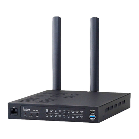
Icom VE-PG2 User manual

TABLE OF CONTENTS
2
1 BRIDGE MODE APPLICATION.............................................................................5
■ Unicast mode operation......................................................................................6
2 SELECTIVE CALL MODE APPLICATION ..........................................................17
■ Using with in-house sound system ...................................................................18
■ Using with an emergency device......................................................................28
■ Using with a headset ........................................................................................39
3 VE-PG2 SETTING SCREEN ................................................................................49
■ Setting screen descriptions ..............................................................................52
■ Connection setting (Bridge mode) ....................................................................53
3-1 Operating mode .........................................................................................53
3-2 IP network connection Transceiver 1 (TRX1)–Transceiver 3 (TRX3) .........57
3-3 IP network connection EXT Input (EXT IN)................................................61
3-4 IP network connection EXT Output (EXT OUT) .........................................65
3-5 IP network connection EXT I/O (EXT)........................................................68
3-6 IP network connection Emergency notice ..................................................71
3-7 TRX/EXT Transceiver 1 (TRX1)–Transceiver 3 (TRX3)..............................74
3-8 TRX/EXT EXT Input (EXT IN) ....................................................................78
3-9 TRX/EXT EXT Output (EXT OUT) .............................................................83
3-10 VoIP call detail Common setting...............................................................85
3-11 Emergency notice ....................................................................................87
3-12 Abnormal condition monitor .....................................................................88
■ Connection setting (Selective call mode)..........................................................89
3-13 Operating mode .......................................................................................89
3-14 IP network connection Transceiver 1 (TRX1)–Transceiver 3 (TRX3) .......91
3-15 IP network connection EXT Input (EXT IN)..............................................93
3-16 IP network connection Emergency notice ................................................95
3-17 TRX/EXT Transceiver 1 (TRX1)–Transceiver 3 (TRX3)............................96
3-18 TRX/EXT EXT Input (EXT IN) ................................................................102
3-19 TRX/EXT EXT output (EXT OUT) ..........................................................107
3-20 VoIP call detail Transceiver 1 (TRX1) – Transceiver 3 (TRX3) ...............115
3-21 VoIP call detail EXT Input (EXT IN)........................................................117
3-22 VoIP call detail EXT Output (EXT OUT) .................................................119
3-23 VoIP call detail Common setting.............................................................121
3-24 Numbering plan......................................................................................124
3-25 Priority call control..................................................................................128
3-26 Emergency notice ..................................................................................129

TABLE OF CONTENTS
3
3-27 Abnormal condition monitor ...................................................................130
■ Network setting...............................................................................................131
3-28 LAN IP....................................................................................................131
■System setting ................................................................................................133
3-29 Administrator ..........................................................................................133
3-30 Clock ......................................................................................................134
3-31 SYSLOG ................................................................................................135
3-32 SNMP.....................................................................................................136
■Information......................................................................................................137
3-33 Network information ...............................................................................137
3-34 SYSLOG ................................................................................................139
3-35 Call/Reception record.............................................................................140
3-36 Information list for IP connection............................................................141
4 MAINTENANCE.................................................................................................143
■ How to restrict of access ...............................................................................144
■ How to set the VE-PG2 internal clock time.....................................................145
■ How to save the VE-PG2 setting to the PC ....................................................146
■ How to load the saved file to the VE-PG2.......................................................147
■ How to initialize the VE-PG2...........................................................................148
■ Firmware updating..........................................................................................150
5 REFERENCE .....................................................................................................155
■ Troubleshooting ..............................................................................................156
■ Connect with the VE-PG2 using Telnet...........................................................158

4

SECTION 1
BRIDGE MODE APPLICATION
This section describes the VE-PG2 setting example in the bridge mode.
5
1 BRIDGE MODE APPLICATION.............................................................................5
■ Unicast mode operation......................................................................................6

6
BRIDGE MODE APPLICATION
1
In the Unicast mode, the VE-PG2 specifies a port number, IP address and calls a
specified transceiver that is connected to the VE-PG2.
The following descriptions are based on the step by step example shown below.
Example: Operating VE-PG2 in local area network.
Transceiver B3
[TRX2]
Transceiver A2
[TRX1]
(Port number: 21500)
HUB
Transceiver A1
[TRX1]
[Area A]
[LAN]
192.168.0.2
VE-PG2
1 2 3 4 5
[Area B]
Transceiver B2
[TRX1]
(Port number: 21500)
[TRX1]
Transceiver B1
[LAN]
192.168.0.3
VE-PG2
If you connect the VE-PG2 to a global network (internet),
you can communicate anywhere through the IP network
without using hub.
CAUTION:
To connect the transceivers or repeaters, use only the following cables:
OPC-2073 (For the transceivers) or OPC-2074 (For the repeaters).
Connect the specified cables to [TRX1], [TRX2] or [TRX3] only.
Using another cable, like an Ethernet cable may damage the VE-PG2,
transceivers or repeaters.
Connect to the transceiver A2’s speaker jack.
Connect to the transceiver B2’s speaker jack.
NOTE: First, connect the transceiver
to the VE-PG2 using the optional
OPC-2073. Then turn ON the power
to the transceiver and the VE-PG2.
NOTE: First, connect the transceiver
to the VE-PG2 using the optional
OPC-2073. Then turn ON the power
to the transceiver and the VE-PG2.
Turn the transceivers’ power ON, and
then set the Transceiver A2’s volume
control to the 12 o’clock position.
Turn the transceivers’ power ON, and
then set the Transceiver B2’s volume
control to the 12 o’clock position.
■Unicast mode operationUnicast mode operation

7
BRIDGE MODE APPLICATION 1
Step 1 [Area A]–Setting the IP address for Area A
Place the mouse pointer on “Network setting,” and then click “LAN IP” shown in the“Network setting,” and then click “LAN IP” shown in theNetwork setting,” and then click “LAN IP” shown in the,” and then click “LAN IP” shown in the” and then click “LAN IP” shown in the“LAN IP” shown in theLAN IP” shown in the” shown in theshown in the
list.
Set the VE-PG2’s IP address in Area A.
• Click [Save and Reboot]
after setting.
2
3
4
5
6
7
8
9
10
11
1
Enter “192.168.0.2.”192.168.0.2.”.”

8
BRIDGE MODE APPLICATION
1
Step 2 [Area A]–Setting IP communication mode
Place the mouse pointer on “Connection setting,” and then click “Operating mode”“Connection setting,” and then click “Operating mode”Connection setting,” and then click “Operating mode”,” and then click “Operating mode”” and then click “Operating mode”“Operating mode”Operating mode””
shown on the list.
Set the IP communication mode for the transceiver A2.
■Unicast mode operation (Continued)
• Click [Save and Reboot]
after setting.
Click to select “UnicastUnicast
mode” option.” option.

9
BRIDGE MODE APPLICATION 1
Step 3 [Area A]–Setting the IP network connection
Place the mouse pointer on “Connection setting,” and then on “IP network“Connection setting,” and then on “IP networkConnection setting,” and then on “IP network,” and then on “IP network” and then on “IP network
connection,” and then click “Transceiver 1 (TRX1)and then click “Transceiver 1 (TRX1)click “Transceiver 1 (TRX1)“Transceiver 1 (TRX1)Transceiver 1 (TRX1)” shown on the list.
Set the IP address for the transceiver A2.
• Click [Save] after setting.
Enter “192.168.0.3.”192.168.0.3.”.”
2
3
4
5
6
7
8
9
10
11
1

10
BRIDGE MODE APPLICATION
1
Step 4 [Area A]–Confirming IP network connection
Place the mouse pointer on “Connection setting,” and then on “IP network“Connection setting,” and then on “IP networkConnection setting,” and then on “IP network,” and then on “IP network” and then on “IP network
connection,” and then click “Transceiver 1 (TRX1)and then click “Transceiver 1 (TRX1)click “Transceiver 1 (TRX1)“Transceiver 1 (TRX1)Transceiver 1 (TRX1)” shown on the list.
The connection status of the transceiver A2 to the IP network can be displayed on
the screen.
• Confirm the status message “During transmit” is displayed.“During transmit” is displayed.During transmit” is displayed.” is displayed.is displayed.
■Unicast mode operation (Continued)
Click
Confirm

11
BRIDGE MODE APPLICATION 1
2
3
4
5
6
7
8
9
10
11
1
Step 5 [Area B]–Setting IP address setting for Area B
Place the mouse pointer on “Network setting,” and then click “LAN IP” shown in the“Network setting,” and then click “LAN IP” shown in theNetwork setting,” and then click “LAN IP” shown in the,” and then click “LAN IP” shown in the” and then click “LAN IP” shown in the“LAN IP” shown in theLAN IP” shown in the” shown in theshown in the
list.
Set the VE-PG2’s IP address in Area B.
• Click [Save and Reboot]
after setting.
Enter “192.168.0.3.”192.168.0.3.”.”

12
BRIDGE MODE APPLICATION
1
Step 6 [Area B]–Setting IP communication mode
Place the mouse pointer on “Connection setting,” and then click “Operating mode”“Connection setting,” and then click “Operating mode”Connection setting,” and then click “Operating mode”,” and then click “Operating mode”” and then click “Operating mode”“Operating mode”Operating mode””
shown on the list.
Set the IP communication mode for the transceiver B2.
■Unicast mode operation (Continued)
• Click [Save and Reboot]
after setting.
Click to select “UnicastUnicast
mode” option.” option.

13
BRIDGE MODE APPLICATION 1
2
3
4
5
6
7
8
9
10
11
1
Step 7 [Area B]–Setting theSetting the IP network connection
Place the mouse pointer on “Connection setting,” and then on “IP network“Connection setting,” and then on “IP networkConnection setting,” and then on “IP network,” and then on “IP network” and then on “IP network
connection,” and then click “Transceiver 1 (TRX1)and then click “Transceiver 1 (TRX1)click “Transceiver 1 (TRX1)“Transceiver 1 (TRX1)Transceiver 1 (TRX1)” shown on the list.
Set the IP address for the transceiver B2.
• Click [Save] after setting.
Enter “192.168.0.2.”192.168.0.2.”.”

14
BRIDGE MODE APPLICATION
1
Step 8 Confirming IP network connectionConfirming IP network connection
Place the mouse pointer on “Connection setting,” and then on “IP network“Connection setting,” and then on “IP networkConnection setting,” and then on “IP network,” and then on “IP network” and then on “IP network
connection,” and then click “Transceiver 1 (TRX1)and then click “Transceiver 1 (TRX1)click “Transceiver 1 (TRX1)“Transceiver 1 (TRX1)Transceiver 1 (TRX1)” shown on the list.
The connection status of the transceiver B2 to the IP network can be displayed on
the screen.
• Confirm the status message “During transmit” is displayed.“During transmit” is displayed.During transmit” is displayed.” is displayed.is displayed.
■Unicast mode operation (Continued)
Click
Confirm

15
BRIDGE MODE APPLICATION 1
2
3
4
5
6
7
8
9
10
11
1
Step 9 Operation
q Set transceivers A2 and B2 AF volume to the 12 o’clock position.’clock position.clock position.
w Turn transceivers A1 and B1 power ON, and select the same operating channel
as transceivers A2 and B2.
• See the transceiver’s instruction manual when setting the channel, if necessary.
e While holding down transceiver A1’s [PTT] in Area A, speak into the microphone
at your normal voice level to call transceiver B1 in Area B.
Release transceiver A1’s [PTT] to receive.
r While holding down transceiver B1’s [PTT] of Area B, speak into the microphone
at your normal voice level to reply to transceiver A1 in Area A.
Release transceiver B1’s [PTT] to receive.
Example: Operating VE-PG2 in local area network.
Transceiver B3
[TRX2]
Transceiver A2
[TRX1]
(Port number: 21500)
HUB
Transceiver A1
[TRX1]
[Area A]
[LAN]
192.168.0.2
VE-PG2
1 2 3 4 5
[Area B]
Transceiver B2
[TRX1]
(Port number: 21500)
[TRX1]
Transceiver B1
[LAN]
192.168.0.3
VE-PG2
If you connect the VE-PG2 to a global network (internet),
you can communicate anywhere through the IP network
without using hub.
CAUTION:
To connect the transceivers or repeaters, use only the following cables:
OPC-2073 (For the transceivers) or OPC-2074 (For the repeaters).
Connect the specified cables to [TRX1], [TRX2] or [TRX3] only.
Using another cable, like an Ethernet cable may damage the VE-PG2,
transceivers or repeaters.
CAUTION:
To connect the transceivers or repeaters, use only the following cables:
OPC-2073 (For the transceivers) or OPC-2074 (For the repeaters).
Connect the specified cables to [TRX1], [TRX2] or [TRX3] only.
Using another cable, like an Ethernet cable may damage the VE-PG2,
transceivers or repeaters.
Connect to the transceiver A2’s speaker jack.
Connect to the transceiver B2’s speaker jack.
NOTE: First, connect the transceiver
to the VE-PG2 using the optional
OPC-2073. Then turn ON the power
to the transceiver and the VE-PG2.
NOTE: First, connect the transceiver
to the VE-PG2 using the optional
OPC-2073. Then turn ON the power
to the transceiver and the VE-PG2.
Turn the transceivers’ power ON, and
then set the Transceiver A2’s volume
control to the 12 o’clock position.
Turn the transceivers’ power ON, and
then set the Transceiver B2’s volume
control to the 12 o’clock position.

16

17
SECTION 2
SELECTIVE CALL MODE
APPLICATION
This section describes the VE-PG2 setting example in the selective call mode.
2 SELECTIVE CALL MODE APPLICATION ..........................................................17
■ Using with in-house sound system ...................................................................18
■ Using with an emergency device......................................................................28
■ Using with a headset ........................................................................................39

18
SELECTIVE CALL MODE APPLICATION
2
The received audio can be sent through the [OUT] port for an in-house sound
system to make an announcement from transceiver 2.
• Transceiver 2 can communicate with other transceivers.
■Using with in-house sound systemUsing with in-house sound system
Transceiver 2
Other transceivers
External
amplifier
External
device
[OUT]
Call destination number: 4
[IN]
VE-PG2
192.168.0.2
Transceiver 1
[TRX1]
[TRX1]
CAUTION:
To connect the transceivers or repeaters, use only the following cables:
OPC-2073 (For the transceivers) or OPC-2074 (For the repeaters).
Connect the specified cables to [TRX1], [TRX2] or [TRX3] only.
Using another cable, like an Ethernet cable may damage the VE-PG2,
transceivers or repeaters.
Connect to the transceiver 1’s speaker jack.
NOTE: First, connect the transceiver
to the VE-PG2 using the optional
OPC-2073. Then turn ON the power
to the transceiver and the VE-PG2.
For in-house sound (BGM)
Turn the transceivers’ power ON,
and then set the Transceiver 1’s
volume control to the 12 o’clock
position.

19
SELECTIVE CALL MODE APPLICATION 2
Step 1 Setting the IP address setting
Place the mouse pointer on “Network setting,” and then click “LAN IP” shown in the“Network setting,” and then click “LAN IP” shown in theNetwork setting,” and then click “LAN IP” shown in the,” and then click “LAN IP” shown in the” and then click “LAN IP” shown in the“LAN IP” shown in theLAN IP” shown in the” shown in theshown in the
list.
Set the VE-PG2’s IP address.
• Click [Save and Reboot]
after setting.
2
3
4
5
6
7
8
9
10
11
1
Enter “192.168.0.2.”192.168.0.2.”.”

20
SELECTIVE CALL MODE APPLICATION
2
■Using with in-house sound system
Step 2 Setting the VE-PG2 Operating mode
Place the mouse pointer on “Connection setting,” and then click “Operating mode”“Connection setting,” and then click “Operating mode”Connection setting,” and then click “Operating mode”,” and then click “Operating mode”” and then click “Operating mode”“Operating mode”Operating mode””
shown on the list.
Set the Operating mode for the VE-PG2.
• Click [Save and Reboot]
after setting.
Click to select “SelectiveSelective
call mode” option.” option.
Other manuals for VE-PG2
5
Table of contents
Other Icom Gateway manuals