Icom IC-R75 User manual

INSTRUCTION MANUAL
COMMUNICATIONS RECEIVER
iR75

i
IMPORTANT
READ THIS INSTRUCTION MANUAL
CAREFULLY before attempting to operate the re-
ceiver.
SAVE THIS INSTRUCTION MANUAL. This
manual contains important safety and operating in-
structions for the IC-R75.
EXPLICIT DEFINITIONS
RNEVER apply AC to the [DC13.8V] jack on the re-
ceiver rear panel.This could cause a fire or ruin the re-
ceiver.
RNEVER apply more than 16 V DC, such as a 24 V
battery, to the [DC13.8V] jack on the receiver rear
panel.This could cause a fire or ruin the receiver.
RNEVER let metal, wire or other objects touch any
internal part or connectors on the rear panel of the re-
ceiver.This may result in an electric shock.
NEVER expose the receiver to rain, snow or any liq-
uids.
AVOID using or placing the receiver in areas with tem-
peratures below –10°C (+14°F) or above +60°C
(+140°F). Be aware that temperatures on a vehicle’s
dashboard can exceed 80°C (+176°F), resulting in per-
manent damage to the receiver if left there for ex-
tended periods.
AVOID placing the receiver in excessively dusty envi-
ronments or in direct sunlight.
AVOID placing the receiver against walls or putting
anything on top of the receiver. This will obstruct heat
dissipation.
Place unit in a secure place to avoid inadvertent use by chil-
dren.
During mobile operation, DO NOT operate the receiver
without running the vehicle’s engine. When receiver
power is ON and your vehicle’s engine is OFF, the ve-
hicle’s battery will soon become exhausted.
Make sure the receiver power is OFF before starting
the vehicle.This will avoid possible damage to the re-
ceiver by ignition voltage spikes.
The receiver comes with the following accessories.
Qty.
qAC adapter (AD-55/A/V)* ..................................... 1
wDC power cable (OPC-869)* ............................... 1
eFuse (FGB 3 A; internal use) ............................... 1
rFuse (FGB 3 A; for DC cable)* ............................ 2
*Either AC adapter + 1 fuse (q, e) or DC power cable + 3
fuses (w, e, r) are supplied depending on versions.
PRECAUTIONS
SUPPLIED ACCESSORIES
Versions of the IC-R75 which display the “CE” symbol on
the serial number seal comply with the European har-
monised standard ETS300 684 (EMC product standard
for Commercially Available Amateur Radio Equipment).
WORD
R
WARNING
CAUTION
NOTE
DEFINITION
Personal injury, fire hazard or electric
shock may occur.
If disregarded, inconvenience only.
No risk of personal injury, fire or
electric shock.
Equipment damage may occur.
qw
er

1
1
TABLE OF CONTENTS
IMPORTANT .............................................................. i
EXPLICIT DEFINITIONS ........................................... i
PRECAUTIONS ......................................................... i
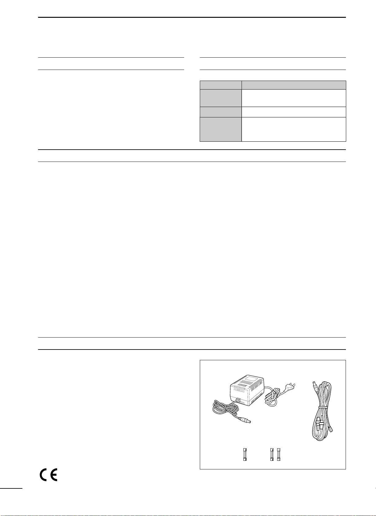
SUPPLIED ACCESSORIES ...................................... i
1 TABLE OF CONTENTS ....................................... 1
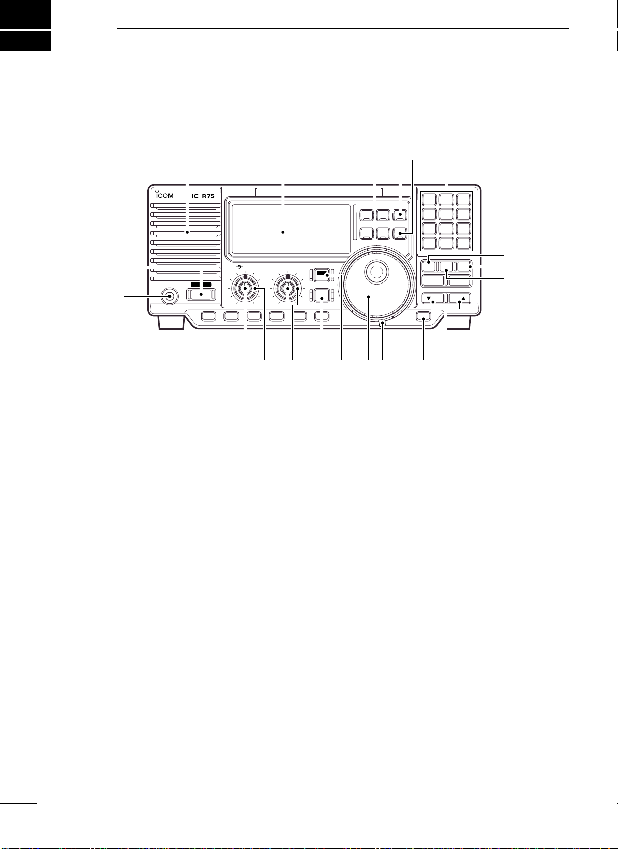
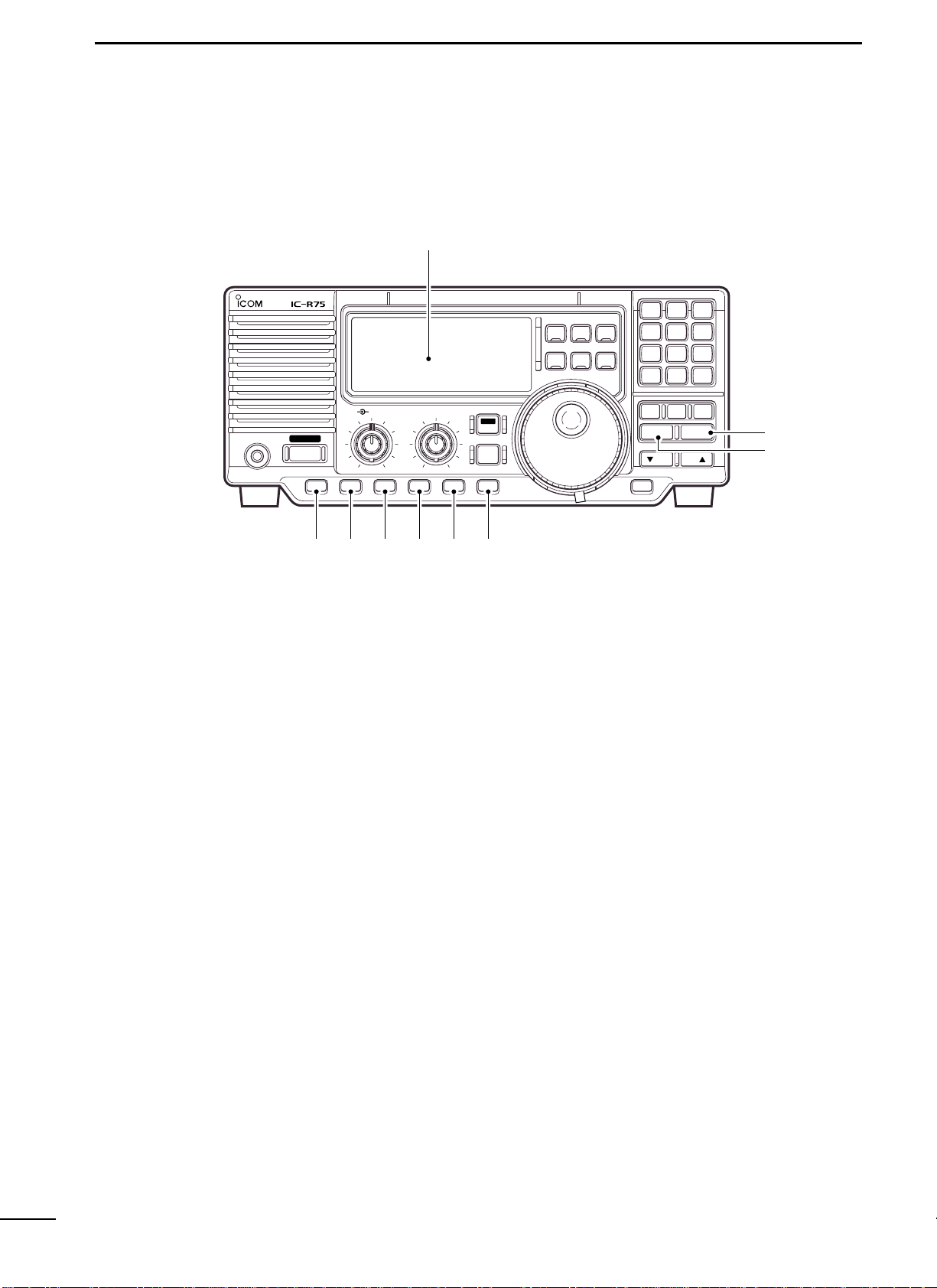
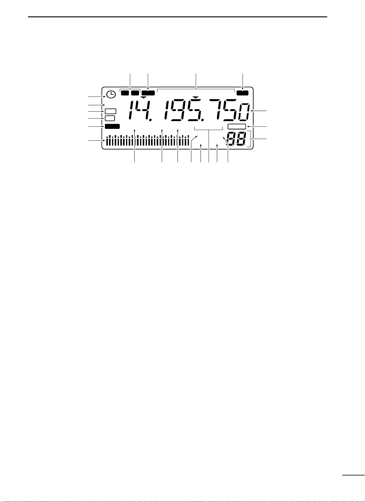
2 PANEL DESCRIPTION ................................... 2–6
■Front panel ........................................................ 2
■Function display ................................................. 5
■Rear panel ......................................................... 6
3 INSTALLATION AND CONNECTIONS ......... 7–10
■Grounding .......................................................... 7
■Receiver stand ................................................... 7
■Optional bracket and carrying handle ................ 7
■Connections ...................................................... 8
■Antenna connection ........................................... 9
■Tape recorder connections ................................ 9
■Transceive function ............................................ 9
■FSK and AFSK (SSTV) connections ............... 10
■Connecting to a PC ......................................... 10
4 FREQUENCY SETTING .............................. 11–13
■Read me first ................................................... 11
■Using the keypad ............................................. 11
■Frequency setting ............................................ 12
■Dial lock function ............................................. 13
5 RECEIVE FUNCTIONS ............................... 14–20
■Mode selection ................................................ 14
■Squelch and RF gain ....................................... 14
■Twin PBT operation ......................................... 15
■Noise blanker ................................................... 15
■Preamp ............................................................ 16
■Attenuator ........................................................ 16
■AGC time constant .......................................... 16
■Antenna selection ............................................ 16
■CW reverse mode ............................................ 17
■CW pitch control .............................................. 17
■RTTY reverse mode ........................................ 17
■Filter selection ................................................. 18
■Filter set mode ................................................. 19
■Optional noise reduction function .................... 20
■Optional auto notch function ............................ 20
6 MEMORY OPERATION ............................... 21–24
■Memory channels ............................................ 21
■Memory channel selection ............................... 21
■Memory channel programming ........................ 22
■Frequency transferring .................................... 23
■Memory names ................................................ 24
■Memory clearing .............................................. 24
7 SCANS ........................................................ 25–27
■Scan types ....................................................... 25
■Preparation ...................................................... 25
■Programmed scan operation ........................... 26
■Memory/select memory scan operation .......... 26
■Setting select memory channels ..................... 26
■Priority watch operation ................................... 27
■Auto memory write scan operation .................. 27
8 CLOCK ANDTIMERS ................................. 28–29
■Setting the current time ................................... 28
■Setting power-on time ...................................... 28
■Setting power-off time ...................................... 29
■Setting sleep timer period ................................ 29
9 SET MODE .................................................. 30–33
■Set mode description ....................................... 30
10 OPTION INSTALLATIONS ....................... 34–35
■Opening the receiver’s case ............................ 34
■CR-282 HIGH STABILITY CRYSTAL UNIT .......... 34
■UT-102 VOICE SYNTHESIZER UNIT .................. 34
■UT-106 DSP UNIT ............................................. 35
■Optional IF filters ............................................. 35
11 MAINTENANCE ........................................ 36–37
■Troubleshooting ............................................... 36
■Resetting the CPU ........................................... 36
■Fuse replacement ............................................ 37
■Clock backup battery replacement .................. 37
12 SPECIFICATIONS ........................................... 38
13 OPTIONS ......................................................... 39
14 CONTROL COMMAND ............................ 40–43
■Remote jack (CI-V) information ....................... 40

■Front panel
qPOWER SWITCH [POWER]
➥Push momentarily to turn power ON.
•Turn the optional DC power supply ON in advance.
➥Push for 2 sec. to turn power OFF.
wHEADPHONE JACK [PHONES] (p. 8)
Accepts headphones.
•When headphones are connected, the internal speaker
or connected external speaker does not function.
eAF CONTROL [AF] (inner control)
Varies the audio output level from the speaker.
rRF GAIN/SQUELCH CONTROL [RF/SQL]
(outer control; pgs.14, 30)
Adjusts the squelch threshold level.The squelch re-
moves noise output from the speaker (closed con-
dition) when no signal is received.
•The squelch is particularly effective for FM. It is also
available for other modes.
•The control can be set as the squelch plus RF gain con-
trols or squelch control only (RF gain is fixed at maxi-
mum) in set mode.
tPASSBANDTUNING CONTROLS [TWIN PBT]
(p. 15)
Adjust the receiver’s “passband width”of the 455
kHz and 9 kHz IF filters for the inner and outer con-
trols, respectively.
•Set to the center positions when not in use.
yCLOCK MODE SWITCH [CLOCK] (p. 28)
Toggles between frequency indication and clock in-
dication when pushed.
uANTENNA SELECTOR/SET MODE SWITCH
[ANT/SET] (pgs. 16, 30)
➥While in a frequency indication, enters set mode
when pushed.
➥While in a frequency indication, toggles between
the antenna 1 and 2 connectors when pushed for
2 sec.
➥While in the clock indication, enters time setting
condition when pushed for 2 sec.
➥While in a timer indication, toggles the timer ON
or OFF when pushed.
iTUNING DIAL
Changes the displayed frequency, selects set mode
items, etc.
oTUNING DIALTENSION LATCH
Adjusts the tension of the tuning dial.
!0 LOCK/SPEECH SWITCH [LOCK] (pgs. 13, 34)
➥Toggles the frequency lock function ON and OFF.
➥Announces the selected readout frequency when
an optional UT-102 is installed and when pushed
for 2 sec.
2
2
PANEL DESCRIPTION
FIL
TS
CW/RTTY
FM
SSB
AM
PHONES POWER
RF/SQL TWIN PBTAF
COMMUNICATIONS RECEIVER
DN UP
12
ABC
3
DEF
4
GHI
5
JKL
6
MNO
7
PRS
8
TUV
9
WXY
.0
QZ
ENT
V/M MW
SEL SCAN
CLR
LOCK
AGCNBANFNRATT
P.AMP
SET
CLOCK
ANT
Function display (p. 5)Speaker
q
w
e r t y i o !0 !1
!3
!4
!5!6!7!8
!2
u

3
2
PANEL DESCRIPTION
!1 MEMORY CHANNEL UP/DOWN SWITCHES
[√√DN]/[UP∫∫](p. 21)
➥Select a memory channel.
➥Select a set mode contents while in set mode.
➥Select a timer or time indication while in clock in-
dication.
➥Select a filter set mode contents while in filter set
mode.
!2 MEMORY WRITE SWITCH [MW] (pgs. 22, 27)
➥Stores the displayed frequency and operating
mode into the selected memory channel when
pushed for 2 sec.
➥Toggles the programmed scan and auto memory
write scan when pushed.
!3 CLEAR SWITCH [CLR] (p. 24)
➥Clears the input digits while inputting a frequency
or memory channel number.
➥Clears the selected memory channel contents
when pushed for 2 sec. in memory mode.
•This switch does not function in VFO mode.
!4 VFO/MEMORY SWITCH [V/M] (pgs. 21, 23)
➥Toggles the operating mode between VFO mode
and memory mode when pushed.
➥Selects a memory channel for inputting a mem-
ory channel number when pushed.
➥Transfers the memory contents to VFO when
pushed for 2 sec.
!5 KEYPAD (pgs. 11, 21)
The keypad can be used for several functions as
below:
•Keypad then [ENT]
—Direct frequency input.
•Keypad then [V/M]
—Memory channel selection.
•[ENT] then keypad in memory name indication
mode
—Alphanumeric input for memory name, etc.
!6 QUICKTUNING STEP SWITCH [TS] (pgs. 12, 13)
➥Selects a quick tuning step or turns the quick tun-
ing step OFF.
•While the quick tuning indicator (") is displayed, the
frequency can be changed in kHz or MHz steps.
➥While the quick tuning step is OFF, turns the 1 Hz
step ON and OFF when pushed for 2 sec.
•1 Hz indication appears and the frequency can be
changed in 1 Hz steps.
➥While the kHz quick tuning step is selected, en-
ters tuning step set mode when pushed for 2 sec.
➥While the memory name indication is selected in
memory mode, pushing this switch shows the op-
erating frequency; and rotating the tuning dial
while pushing this switch changes the frequency
temporally.
!7 FILTER SWITCH [FIL] (pgs. 18, 19)
➥Push momentarily to toggle between the pre-pro-
grammed normal, wide and narrow IF filters for
the selected operating mode.
➥Push for 2 sec. to enter filter set mode.
!8 MODE SWITCHES [SSB]/[CW/RTTY]/[AM]/[FM]
(p. 14)
Select an operating mode.
•Push [SSB] to toggle between LSB and USB.
•Push [CW/RTTY] to toggle between CW and RTTY.
•Push [CW/RTTY] for 2 sec. to toggle between CW and
CW reverse or RTTY and RTTY reverse.
•Push [AM] to toggle between AM and S-AM.
•Push [FM] to select FM.

4
2PANEL DESCRIPTION
■Front panel (continued)
!9 PREAMP SWITCH [P.AMP] (p. 16)
Push to toggle between preamp-1 and preamp-2 or
turn the preamp OFF.
@0 ATTENUATOR SWITCH [ATT] (p. 16)
Push to toggle the 20 dB attenuator function ON
and OFF.
@1 NOISE REDUCTION SWITCH [NR] (p. 20)
➥Toggles the optional noise reduction function ON
and OFF when pushed. Functions in SSB, CW
and RTTY modes.An optional UT-106 DSP UNIT is
required.
➥Enters noise reduction level set mode when
pushed for 2 sec. An optional UT-106 DSP UNIT is
required.
@2 AUTOMATIC NOTCH FILTER SWITCH [ANF]
(p. 20)
Push to turn the optional automatic notch filter for
receiving AM signals ON and OFF. An optional
UT-106 DSP UNIT is required.
@3 NOISE BLANKER SWITCH [NB] (p. 15)
Toggles the noise blanker ON and OFF. The noise
blanker reduces pulse-type noise such as that gen-
erated by automobile ignition systems.This function
is not effective for FM, or non pulse-type noise.
@4 AGC SWITCH [AGC] (p. 16)
➥Toggles the AGC (Automatic Gain Control) time
constant fast and slow when pushed.
➥Toggles the AGC function ON and OFF when
pushed for 2 sec.
@5 SELECT SWITCH [SEL] (pgs. 24, 26)
➥Toggles the select memory setting ON and OFF
when pushed in memory mode.
➥Toggles the memory name indication ON and
OFF when pushed for 2 sec. in memory mode.
@6 SCAN SWITCH [SCAN] (p. 25)
➥Push momentarily to start/stop the programmed
scan in VFO mode.
➥Push momentarily to start/stop the memory scan
in memory mode.
➥Push for 2 sec. to start the priority watch in VFO
mode.
•Push [SCAN] again to cancel the priority watch.
FIL
TS
CW/RTTY
FM
SSB
AM
PHONES POWER
RF/SQL TWIN PBTAF
COMMUNICATIONS RECEIVER
DN UP
12
ABC
3
DEF
4
GHI
5
JKL
6
MNO
7
PRS
8
TUV
9
WXY
.0
QZ
ENT
V/M MW
SEL SCAN
CLR
LOCK
AGCNBANFNRATT
P.AMP
SET
CLOCK
ANT
Function display (p. 5)
!9 @0 @1 @2 @3 @4
@6
@5

■Function display
qTIMER INDICATOR (p. 28)
Appears when power on/off timer or sleep timer is
in use.
wDSP UNIT INDICATOR (p. 35)
Appears when an optional UT-106 DSP UNIT is in-
stalled.
eAUTOMATIC NOTCH FILTER INDICATOR (p. 20)
Appears when the optional automatic notch filter is
in use.
rNOISE REDUCTION INDICATOR (p. 20)
Appears when the optional noise reduction function
is in use.
tLOCK INDICATOR (p. 13)
Appears when the dial lock function is in use.
ySIGNAL METER
➥Shows the relative receive signal strength.
➥Shows the S-meter squelch level when used.
uPREAMP INDICATOR (p. 16)
Appears when antenna preamp-1 or preamp-2 is in
use.
iATTENUATOR INDICATOR (p. 16)
Appears when the attenuator function is in use.
oANTENNA INDICATORS (p. 16)
Indicate which antenna connector is in use.
!0 NOISE BLANKER INDICATOR (p. 15)
Appears when the noise blanker function is in use.
!1 SCAN INDICATOR (p. 25)
➥Appears when scan or priority watch is activated.
➥Flashes when scan or priority watch is paused.
!2 AGC INDICATORS (p. 16)
➥“AGC”appears when slow AGC time constant is
selected.
➥“F.AGC”appears when fast AGC time constant is
selected.
➥“AGC OFF”appears when the AGC function is
turned OFF.
➥“F.AGC”blinks while scanning or while using
band scope via an optional RS-R75.
!3 MEMORY MODE INDICATOR (p. 21)
Indicates memory mode is selected.
!4 VFO MODE INDICATOR
Indicates VFO mode is selected.
!5 MEMORY CHANNEL NUMBER READOUT
(p. 21)
➥Shows the selected memory channel number.
➥“S”appears when the displayed memory channel
is designated as a select memory channel.
!6 BLANK MEMORY INDICATOR
Shows that the displayed memory channel is not
programmed.
•This indicator appears both in VFO and memory modes.
!7 FREQUENCY READOUT
Shows the operating frequency.
!8 RECEIVE INDICATOR
Appears while receiving a signal or when the
squelch is open.
!9 MODE INDICATORS (p. 14)
Indicate the selected operating mode.
@0 REVERSE MODE INDICATOR (p. 17)
Indicates a reverse operating mode is selected.
@1 WIDE/NARROW FILTER INDICATORS (p. 18)
➥“ç”appears when the wide IF filter is selected.
➥“ã”appears when the narrow IF filter is selected.
5
2
PANEL DESCRIPTION
DSP
BLANKBLANK
S
RTTY
PREAMP
TIMER
S1 3 57920 40 60
dB
F.AGC OFFANTATT
LSBUSBCWS
-
AMFM
REV
NW
ANF
NR
LOCK
R X
MEMO
SCAN
N B
VFO
1122
q
w
e
r
t
y
uio!0!1!2!3!4
!5
!6
!7
!8!9@0@1

6
2PANEL DESCRIPTION
■Rear panel
qRECORDER REMOTE JACK [REC REMOTE]
Controls the running of a tape recorder for record-
ing. Connects to the REMOTE jack on a tape
recorder.
•This function can be turned OFF in set mode. (p.32)
wRECORDER JACK [REC]
Outputs receive audio signals.Connects to the AUX
or LINE IN jack on a tape recorder.
eRS-232C CONNECTOR [RS-232C]
Connects an RS-232C cable. An RS-232C cable
can be used to connect the receiver to a PC. In this
way commands can be sent to the receiver via the
PC.
rCI-V REMOTE CONTROL JACK [REMOTE]
Allows connection to an Icom CI-V system trans-
ceiver or another receiver for the transceive func-
tion. Also connects to a PC with several receivers
for command control via an optional CT-17 CI-V
LEVEL CONVERTER.
tEXTERNAL SPEAKER JACK [EXT SP]
Connects an 8 Ωexternal speaker, if desired.
•When an external speaker is connected, the internal
speaker does not function.
yMUTE CONTROL JACK [MUTE]
Mutes audio outputs and attenuates the receive sig-
nal input when grounded. Used for CI-V transceive
operation with a transceiver.
uGROUNDTERMINAL [GND] (p. 7)
Connects the black terminal to ground.
iANTENNA 2TERMINAL [ANT2] (p. 9)
Connects the red terminal to a 500 Ωlong wire an-
tenna.
oANTENNA 1 CONNECTOR [ANT1] (p. 9)
Connects a 50 Ωantenna with a PL-259 connector
and a 50 Ωcoaxial cable.
!0 DC POWER JACK [DC13.8V] (p. 8)
➥Connects the supplied AC adapter for versions
with an AC adapter.
➥Connects to a 13.8 V DC power source using the
supplied DC cable for versions without an AC
adapter.
•Current of 1.5 A or greater is required.
DO NOT use a cigarette lighter socket as a
power source when operating in a vehicle. The
plug may cause voltage drops and ignition noise
may be superimposed onto received audio.
qw rt y uieo!0

■Grounding
To prevent accidents involving electricity and interfer-
ence from transceivers, ground the receiver through
the [GND] terminal on the rear panel.
For best results, connect a heavy gauge wire or strap
to a long earth-sunk copper rod.Make the distance be-
tween the [GND] terminal and ground as short as pos-
sible.
RWARNING: NEVER connect the [GND]
terminal to a gas or electric pipe, since the connec-
tion could cause an explosion or electric shock.
■Receiver stand
The base of the receiver has an adjustable stand for
desktop use. Set the stand to one of two angles de-
pending on your operating conditions.
■Optional bracket and
carrying handle
DMounting bracket
An optional IC-MB5 MOBILE MOUNTING BRACKET is avail-
able to install the radio under a table, on a wall, in a
vehicle, etc.
Select an area to mount the receiver keeping in mind
that the weight of the receiver is approx.3 kg.
DCarrying handle
An optional handle allows you to easily carry and
transport the receiver.
Attach the MB-23 CARRYING HANDLE with the supplied
rubber feet as shown.
3
7
INSTALLATION AND CONNECTIONS
Flat washer

8
3INSTALLATION AND CONNECTIONS
FIL
TS
CW/RTTY
FM
SSB
AM
PHONES POWER
RF/SQL TWIN PBTAF
COMMUNICATIONS RECEIVER
DN UP
12
ABC
3
DEF
4
z
5
JKL
6
MNO
7
PRS
8
TUV
9
WXY
.0
z
ENT
V/M MW
SEL SCAN
CLR
LOCK
AGCNBANFNRATT
P.AMP
SET
CLOCK
ANT
AD-55/A/V or
OPC-869
HEADPHONES
REMOTE (p. 9, 32)
Used for computer control and transceive. ANTENNA 2
Connect a long wire
antenna; impedance: 500 Ω.
ANTENNA 1 (p. 9)
Connect a Yagi antenna;
impedance: 50 Ω.
EXTERNAL
SPEAKER (p. 39)
SP-21
GROUND (p. 7)RS-232C JACK (p. 10)
MUTE CONTROL
JACK (p. 6)
RECORDER/
RECORDER
CONTROL (p. 9)
DC13.8V JACK
■Connections

■Tape recorder connections
■Transceive function
9
3
INSTALLATION AND CONNECTIONS
PL-259 CONNECTOR INSTALLATION EXAMPLE
30 mm
10 mm (soft solder)
10 mm
1–2 mm
solder solder
Soft
solder
Coupling ring
Slide the coupling ring
down. Strip the cable
jacket and soft solder.
Slide the connector
body on and solder it.
Screw the coupling ring
onto the connector
body.
Strip the cable as
shown at left. Soft
solder the center con-
ductor. (10 mm ≈3⁄8 in)
q
w
e
r
■Antenna connection
Antennas play a very important role in receiver opera-
tion.Connecting a poor quality antenna to the receiver
will result in less than optimum performance.
When using a 50 Ωantenna, use [ANT1] connector for
connection. When using a 500 Ωlong wire antenna,
use [ANT2] terminal for connection.
The [REC OUT] jack has 350 mV rms/4.7 kΩoutput
for connection to other audio equipment.
[REC REMOTE] jack: Grounds when a signal is
received and squelch opens. If a tape recorder
has a control terminal, this jack can be used for
recording control. (1 A/DC max.)
[REC
REMOTE] [REC OUT]
350 mVrms
4.7 kΩ
[AUX IN] or
[LINE IN] jack
IC-R75
Icom CI-V transceivers or receivers can be connected
via the [REMOTE] jack.The frequency and mode be-
come the same* when either radio is changed.
*When a set frequency is out-of-range for one of the con-
nected transceivers or receivers, the connected radio’s fre-
quency/mode does not change.
[REMOTE]
IC-R75
Icom CI-V transceiver/receiver
Connect to [REMOTE] jack
Be sure the “CIV TRn”item is turned ON in set mode (p.32).

10
3INSTALLATION AND CONNECTIONS
■Connecting to a PC
To connect a terminal unit, TNC or scan converter,
refer to the diagram below.
qConnect a terminal unit as below.
wSelect RTTY mode (or USB, CW modes for HF
band data communications).
eSet the receiver to the desired frequency as at
right.
rSet the connected terminal unit to the appropriate
settings.
•Refer to the terminal unit’s instructions.
The optional 250 Hz CW narrow filters may not
pass RTTY signals.Be sure to select the appropri-
ate IF filters corresponding to the signal width.
(pgs. 18, 19)
Frequency settings depend on the mode used.
FM mode:
[Setting frequency (displayed freq.)]=[Desired
freq.]
USB mode:
[Setting frequency (displayed freq.)]=[Desired
freq.]–[Center of Mark and Space freq.]
CW narrow mode:
[Setting frequency (displayed freq.)]=[Desired
freq.]–[Center of Mark and Space freq.]+[600 Hz]
LSB mode (for amateur RTTY):
[Setting frequency (displayed freq.)]=[Desired
freq.]+[Mark freq.]
The RS-R75 remote control software is available to
perform data setting and remote control of the re-
ceiver.
Refer to the diagram below for connection.
DSystem requirements
To use this program, the following hardware and soft-
ware are required:
•IBM PC compatible computer
•An RS-232C serial port
•Microsoft®Windows®95 or Microsoft®Windows®98
•Intel i486DX4 processor or faster (Pentium®100
MHz or faster recommended)
•At least 16 MB RAM
•At least 10 MB of hard disk space
•At least 640 ×480 pixel, high color (16 bit) display
■FSK and AFSK (SSTV) connections
TU or TNC
AF IN
SQUELCH IN
to [REC]to [REC
REMOTE]
2-conductor 3.5(d) plugs
Personal computer
Personal computer IC-R75
Supplied RS-232C cable (OPC-743)

4
11
FREQUENCY SETTING
■Read me first
The receiver uses memory channels for storage of fre-
quencies (as well as mode, tuning steps, etc.). When
turning power OFF or changing memory channels, the
previously displayed frequency cannot be recalled un-
less it has been stored into a memory channel.
Therefore, when you want to keep a displayed fre-
quency for later recall, you must program it into a
memory channel by pushing [MW] for 2 sec.
See p.22 for details.
■Using the keypad
qPush the numeral keys on the keypad to enter the
MHz digits for the desired frequency.
•If a key is mistakenly pushed, push [CLR] and start
again from the beginning.
•When entering the same MHz digits as the displayed
frequency, this step can be skipped.
wPush [•] on the keypad.
ePush the numeral keys to enter the frequency digits
below 1 MHz.
•If a key is mistakenly pushed, push [CLR] and start
again from the beginning.
rPush [ENT] to set the input frequency.
•When pushing [ENT] after entering the MHz digits, zeros
are automatically entered for the kHz digits.
BLANKBLANK
S1 3 57920 40 60
dB
AGCANT
USB R X
VFO
1
“BLANK”appears above the memory channel
readout until [MW] is pushed for 2 sec.
Push [MW] for 2 sec. after tuning.
[EXAMPLE]: Setting the frequency using the keypad.
USB R X
USB
USB R X
USB R X USB R X
USB R X USB R X R X
USB R X
USB R X
USB R X USB R X
USB R X USB R X USB R X
USB R X
1
5
JKL
8
TUV
.
.
.
0
QZ
5
JKL
8
TUV
USB R X
0
QZ
•To set to 28.00 MHz 2
ABC
8
TUV
ENT
5
JKL
ENT
•To set to 21.050 MHz 2
ABC
•To set to 850 kHz (0.850 MHz)
ENT
ENT
•To change 14.19075 to 14.850 MHz

12
4FREQUENCY SETTING
■Frequency setting
Rotate the tuning dial to change the frequency.
•The frequency changes in increments determined by the
selected tuning step (see below).
•When the lock function is activated (“LOCK”appears), the
frequency cannot be changed via tuning dial.
Push [TS] one or more times to select a quick tuning
step.
DProgrammable tuning steps
Programmable tuning steps are available to suit your
operating requirements.
These tuning steps are:
•Independently selectable for each mode
•Selectable from 0.1, 1, 5, 6.25, 9, 10, 12.5, 20, 25,
100 kHz
qSelect the desired operating mode with [SSB],
[CW/RTTY], [AM] or [FM]. (p.14)
wPush [TS] one or more times until the programma-
ble tuning step indicator, “",”appears above the 1
kHz.
•Rotating the tuning dial changes the frequency accord-
ing to the set tuning step.
ePush [TS] for 2 sec. while the programmable tun-
ing step indicator appears to enter the tuning step
set mode.
rRotate the tuning dial to set the desired tuning step
for the selected mode.
tPush [TS] to exit the tuning step set mode.
yRotate the tuning dial to change the frequency ac-
cording to the set tuning step.
D1 Hz and 10 Hz tuning steps
When both the 1 MHz tuning step and programmable
tuning step, “",”disappear, rotating the tuning dial
changes the frequency in increments of 1 or 10 Hz.
qPush [TS] one or more times until the programma-
ble tuning step indicator or 1 MHz tuning step in-
dicator, “",”disappears.
wPush [TS] for 2 sec. to toggle between the 1 and
10 Hz step settings.
•When the 1 Hz step is selected, the 1 Hz digit appears
in the frequency indication; when the 10 Hz step is se-
lected, the 1 Hz digit disappears from the frequency in-
dication.
USB R X
BLANKBLANK
S1 3 57920 40 60
dB
AGCANT
VFO
1
Programmable tuning
step indicator
10 kHz tuning step is
selected.
[TS]
USB R X
BLANKBLANK
S1 3 57920 40 60
dB
AGCANT
VFO
1
USB R X
BLANKBLANK
S1 3 57920 40 60
dB
AGCANT
VFO
1
Rotating the tuning dial
changes the frequency
in 10 Hz steps.
Rotating the tuning dial
changes the frequency
in 1 Hz steps.
TS
Push for 2 sec.

13
4
FREQUENCY SETTING
D1 MHz quick tuning step
The quick tuning step function allows you to change
the frequency in 1 MHz steps when rotating the tun-
ing dial.
Push [TS] one or more times until the 1 MHz tuning
step indicator, “",”appears above the 1 MHz indica-
tor.
USB R X
BLANKBLANK
S1 3 57920 40 60
dB
AGCANT
VFO
1
Quick tuning step
indicator
10 Hz tuning
1 Hz tuning
momentarily
2 sec.2 sec.
2 sec.
1 MHz tuning
Programmable step tuning
(100 Hz –100 kHz)
Selectable for each mode.
momentarily
momentarily
USB R X USB R X USB R X
USB R X
[TS] SWITCH FLOW CHART
■Dial lock function
The dial lock function prevents accidental changes
caused by the tuning dial.The lock function electroni-
cally locks the dial.
Push [LOCK] momentarily to toggle the lock function
ON and OFF.
•“LOCK”appears in the function display while the lock func-
tion is activated.
USB R X
BLANKBLANK
S1 3 57920 40 60
dB
AGCANT
VFO
1
LOCK
“LOCK”appears while the lock
function is activated.
[LOCK]

5
14
RECEIVE FUNCTIONS
■Mode selection
The following modes are available in the IC-R75:
SSB (LSB/USB), CW, CW REV (CW reverse), FM,
AM, S-AM (Synchronous detection AM), RTTY and
RTTY REV (RTTY reverse).
➥Push [SSB] to toggle between LSB and USB.
➥Push [CW/RTTY] momentarily to toggle between
CW and RTTY.
➥Push [CW/RTTY] for 2 sec. to toggle between CW
and CW reverse or RTTY and RTTY reverse.
➥Push [AM] to toggle between AM and S-AM.
•“S-”blinks when automatic mode selection between
S-AM and AM modes is in use.This can be set in set
mode. (p. 31)
➥Push [FM] to select FM.
The selected mode is indicated in the function dis-
play.
OPERATING MODE SELECTION
SSB
AM
Push momentarily
FM
CW/RTTY
CW CW REV RTTY RTTY REV
AM
Push mode switch
for 2 sec. Push mode switch
momentarily.
S-AM
FM
LSB USB
■Squelch and RF gain
The receiver uses the same control, [RF/SQL], to ad-
just one of either the RF gain or the squelch.
[RF/SQL] adjusts either the RF gain or the squelch
depending on the operating mode selected and the
condition of the RF/SQL item in set mode (p.30).
•[RF/SQL] control priority
* The RF gain is set to maximum level when the [RF/SQL]
is set as [SQL] control.
The RF (Radio Frequency) gain is used to adjust the
receiver gain.
•Shallow rotation moves the S-meter to the right indicating
the signal strength which can be received.
The recommended position for RF gain is the 12
o’clock position since this sets RF gain to the max.
The SQUELCH removes noise output from the
speaker (closed condition) when no signal is re-
ceived.The squelch is particularly effective for FM. It
is also available for the other modes.
•When operating in FM, first rotate the control fully counter-
clockwise. Then, rotate the control clockwise to the point
where the noise just disappears.This is the best position.
The squelch does not open for weak signals when it is set
too deep.
•A segment appears in the S-meter to indicate the S-meter
squelch level.
•When set as the [RF/SQL] control
Set mode
setting USB, LSB,
CW, RTTY AM, S-AM, FM
Sq (SQL) SQL* SQL*
At (AUTO) RF GAIN SQL*
rS (RF/SQL) RF/SQL RF/SQL
Recommended level
Minimum RF gain
Adjustable range
RF gain adjustable
range
Maximum RF gain
Maximum RF gain
Squelch is open. S-meter squelch
S-meter squelch
threshold
Noise squelch threshold
(FM mode)
Shallow Deep
Squelch is open.
S-meter squelch
Noise squelch (FM mode)
•When set as the [SQL] control
•When set as the [RF] control

15
5
RECEIVE FUNCTIONS
■Twin PBT operation
The twin PBT (Passband Tuning) function electroni-
cally narrows the IF passband widths to reduce inter-
ference. Moving both [TWIN PBT] controls to the
same position shifts the IF.
Variable range depends on the filter selection. ±1.29
kHz in 15 Hz steps and ±258 kHz in 3 Hz steps are
available.
PBT OPERATION EXAMPLE
•[TWIN PBT] should normally be set to the center
positions when there is no interference.
•When PBT is used, the audio tone may be
changed.
•PBT may not function with some IF filter combina-
tions.
•Not available for FM mode.
TWIN PBT TWIN PBT
TWIN PBT
IF center frequency Interference Desired signal
Passband
Both controls at
center position Cutting a lower
passband Cutting both higher and
lower passbands
Interference Interference
Desired signal
Passband
■Noise blanker
The noise blanker eliminates pulse-type noise such
as from car ignitions. The noise blanker is not avail-
able for FM mode.
➥Push the [NB] switch to turn the noise blanker ON
or OFF.
•When using the noise blanker, received signals
may be distorted if they are excessively strong.
•The noise blanker function in AM mode can be
deactivated depending on set mode setting. (p.
31)
[NB]

16
5RECEIVE FUNCTIONS
■Preamp
The preamp amplifies received signals in the front
end circuit to improve the S/N ratio and sensitivity.
Turn this function ON when receiving weak signals.
➥Push [P.AMP] to toggle between preamp-1 and
preamp-2 or turn the preamp OFF.
■Attenuator
The attenuator prevents desired signals from distort-
ing when very strong signals are near the desired fre-
quency or when very strong electric fields, such as
from broadcasting stations, are near your location.
➥Push [ATT] toggle the 20 dB attenuator function
ON and OFF.
•“ATT”appears when the attenuator is turned ON.
■AGC time constant
The AGC (Automatic Gain Control) controls receiver
gain to produce a constant audio output level even
when the received signal strength is varied by fading,
etc. Use AGC slow for normal phone operation; AGC
fast for receiving data and searching for signals.
➥Push [AGC] momentary to toggle the AGC time
constant between fast and slow.
•“F.AGC”appears when the fast time constant is se-
lected.
•“AGC”appears when the slow time constant is se-
lected.
➥Push [AGC] for 2 sec. to turn the AGC circuit OFF.
•“AGC OFF”appears when the AGC circuit is turned
OFF.
•Push [AGC] to turn the AGC circuit ON.
USB R X
BLANKBLANK
S1 3 57920 40 60
dB
AGCANT
VFO
1PREAMP 1
“PREAMP”appears while the
preamp is activated.
■Antenna selection
2 types of antenna can be connected to this receiver.
When 2 antennas are connected, select an antenna
depending on the operating condition.
➥Push [ANT(SET)] for 2 sec. to toggle between the
antenna 1 and 2 connectors.
•If a blank memory channel has been selected, push
[V/M] to select VFO mode in advance.
USB R X
BLANKBLANK
S1 3 57920 40 60
dB
AGCANT
VFO
1
“ANT1”appears when the
[ANT1] connector is in use.
USB R X
BLANKBLANK
S1 3 57920 40 60
dB
AGCANT
VFO
1ATT
“ATT”appears while the attenuator
is activated.
USB R X
BLANKBLANK
S1 3 57920 40 60
dB
AGCANT
VFO
1F.AGC
“F.AGC”appears when the fast time
constant is selected.

17
5
RECEIVE FUNCTIONS
■CW reverse mode
CW-R (CW Reverse) mode receives CW signals with
a reverse side CW carrier point like that of LSB and
USB modes.
Use when interfering signals are near a desired signal
and you want to change the interference tone.
qPush [CW/RTTY] once or twice to select CW
mode.
wPush [CW/RTTY] for 2 sec. to toggle between CW
and CW reverse (CW REV).
•Check the interfering tone.
•Receive audio tone response
■RTTY reverse mode
Received characters are occasionally garbled when
the receive signal is reversed between MARK and
SPACE.This reversal can be caused by incorrectTNC
connections, settings, commands, etc.
To receive a reversed RTTY signal correctly, select
RTTY reverse mode.
qPush [CW/RTTY] once or twice to select RTTY
mode.
wPush [CW/RTTY] for 2 sec. to toggle between
RTTY and RTTY reverse (RTTY REV).
•Check the receive signal.
■CW pitch control
The received CW audio pitch and monitored CW
audio can be adjusted to suit your preferences (300
to 900 Hz) without changing the operating frequency.
The received CW audio pitch can be adjusted in 10
Hz steps.
qPush [(ANT)SET] momentarily to enter set mode.
wPush [UPY] or [ZDN] to select the ‘CW PITCH’
item.
eRotate the tuning dial to set the desired CW audio
pitch.
•CW audio pitch is displayed in 10 Hz steps. ‘60’indi-
cates 600 Hz CW audio pitch.
rPush [(ANT)SET] again to exit set mode.
BFO
1/3 octave
Push for 2 sec.
Desired signal
(600 Hz)
CW mode (USB side)
Interference
(800 Hz)
BFO
1/2 octave
Desired signal
(600 Hz)
CW REV mode (LSB side)
Interference
(400 Hz)
CW/RTTY
Shows a 600 Hz CW audio pitch

18
5RECEIVE FUNCTIONS
■Filter selection
The filter selection switches the IF passband width as
shown in the table at right.
The filter selection is automatically memorized in
each mode.
qSelect the desired mode with the mode switches.
wPush [FIL] one or more times to select the desired
filter combination.
•ãor çdoes not appear while in normal IF filter.
•çappears when wide IF filters are selected.
•ãappears when narrow IF filters are selected.
When an optional filter is installed, set the optional
filter in filter set mode. Optional filters are not se-
lected by default.
•Filter construction
CFWS450E (15 kHz)
CFWS450HT (6 kHz)
FL-65 (2.4 kHz)
FL-257 (3.3 kHz)
FL-96 (2.8 kHz)
FL-222 (1.8 kHz)
FL-52A (500 Hz)
FL-53A (250 Hz)
optional
FL-23 (15 kHz)
FL-272 (2.4 kHz)
FL-103 (2.8 kHz)
FL-223 (1.9 kHz)
FL-100 (500 Hz)
FL-232 (350 Hz)
FL-101 (250 Hz)
optional
Mixer
2nd IF signal 3rd IF signal
9 MHz IF filter 455 kHz IF filter
IF Filter Passband
width Recommended
selectivity
9 MHz
FL-100 500Hz/–6dB CW-N,RTTY-N
FL-101 250Hz/–6dB
FL-103 2.8kHz/–6dB SSB-W
CW-N
FL-223 1.9kHz/–6dB SSB-N
455 kHz
FL-52A 500Hz/–6dB CW-N,RTTY-N
FL-53A 250Hz/–6dB CW-N
FL-96 2.8kHz/–6dB SSB-W
FL-232 350Hz/–6dB CW-N,RTTY-N
FL-222 1.8kHz/–6dB SSB-N
FL-257 3.3kHz/–6dB SSB-W
Other manuals for IC-R75
3
Table of contents
Other Icom Receiver manuals

Icom
Icom IC-R5 User manual

Icom
Icom IC-R6 User manual

Icom
Icom IC-PCR1500 User manual

Icom
Icom IC-RX7 Installation and operating instructions

Icom
Icom IC-R2 User manual

Icom
Icom IC-R1500 User manual

Icom
Icom IC-R2 User manual

Icom
Icom IC-R75 User manual

Icom
Icom MXG-5000S User manual

Icom
Icom IC-R9000L User manual
Popular Receiver manuals by other brands

Denon
Denon AVR-2307CI operating instructions

Williams Sound
Williams Sound SoundPlus WIR RX237 Specification sheet

ITRON
ITRON EquaScan FNet installation manual

Shenzhen Optostar Optoelectronics
Shenzhen Optostar Optoelectronics OP-OR124RJ manual

Sat Cruiser
Sat Cruiser DSR-301 ACE user guide

nologo
nologo RX1-LUCI quick start guide