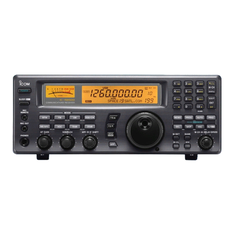
Icom IC-R7000 User manual

INSTRUCTION MANUAL
COMMUNICATIONS
RECEIVER
IC-R7000
lcom
Inc.

FOREWORD
Thank
you
very
much
for
selecting
the
new
IC-R7000
from
ICOM.
The
most
sophisticated,
continuous
coverage receiver
on
the
market
today,
the
IC-R7000
is
the
result
of
both
advanced- ICOM engineering
and
state-of-the-art
computer
interface
technology
from
ICOM
such
as
the
new
CI-V
System:
a
feature
that
allows for easy
and
convenient
computer
control
of
your
IC-R7000.
Equipped
with
99
internal
memories
that
are
completely
owner-programmable,
the
IC-R7000
is
-
unmatched
in
scanning
and
coverage versatility
within
the
25
to
1300MHz
range
and
may
even
cover
frequencies
up
to
2000MHz.
Low
band,
aircraft,
marine, business, FM,
amateur
radio,
emergency
services,
government,
and
television bands -
all
are
conveniently
available
and
immediately
accessible
with
the
IC-R7000.
To
fully
understand
and
appreciate
the
utility
of
your
new
IC-R7000, please
study
this
instruction
manual
carefully
prior
to
operation.
If
you
have
additional
questions
regarding
operation
of
the
IC-R7000,
feel free
to
contact
your
nearest
authorized
ICOM
dealer
or
Service
Center.
UNPACKING
®
® ® -
CD
1.
AC
Power
cable .
2. Fuses
(2A).
2
3. *Fuses 2
4.
RCA
plugs.
2
5.
Earphone
plugs 4
*
USA
version : 1A
Australia,
Europe,
France version :
0.5A

SECTION
SECTION
SECTION
SECTION
SECTION
SECTION
SECTION
SECTION
TABLE OF
CONTENTS
DESCRIPTION
........................................
.
2 SPECIFICATIONS
.....................................
.
3
CONTROL
FUNCTIONS
......................•..........
3-
1
FRONT
PANEL
.•.....................................
3-
2
FREQUENCY
DISPLAY
................................
.
3-3
REAR
PANEL
1
2
3
3
8
9
4
INSTALLATION
AND
CONNECTIONS
....................
11
4-
1
INSTALLATION
LOCATION
.............................
11
4-
2 AC POWER CONNECTION
...............................
11
4-3
ANTENNA
CONNECTION
.•.............................
11
4-4
GROUND
CONNECTION
...•.............................
12
4-
5
EXTERNAL
SPEAKER CONNECTION
.......................
12
4-6
CONNECTION TO TAPE RECORDER
.......................
13
4-7
REMOTE
JACK
CONNECTION
............................
13
5 OPERATIONS
.........................................
14
5 - 1 SETTINGS. . . . . . . . . . . . . . . . . . . . . . . . . . . . . . . . . . . . . . . . . . . . 14
5-2
BASIC
OPERATION
...................................
14
5-3
FREQUENCY
SETTING
.................................
15
5-4
MEMORY
OPERATION
..................................
17
5-5
SCANNING
OPERATION
.................................
19
5 - 6
AUTO
STOP
FUNCTION
............
: . . . . . . . . . . . . . . . . . . . . 28
5-7
M-SET SWITCH
........................................
28
6 PRECAUTIONS
AND
MAINTENANCE
.....................
29
6-
1
OPERATING
WARNING
..................................
29
6-
2
MAINTENANCE
........................................
29
6-3
AC
POWER SUPPLY
MODIFICATIONS
......................
30
7
TROUBLESHOOTING
...................................
31
8 INSIDE VIEWS
........................................
32
8-
1 POWER SUPPLY/DC-DC
CONVERTER
UNIT
...................
32
8-
2 LOGIC
UNIT
..........................................
32
8-3
RF/IF
UNIT
..........................................
33
8-4
MAIN
UNIT
..........................................
33
8-
5
PLL
UNIT
............................................
33
SECTION 9 OPTION
INSTALLATIONS
...............................
34
SECTION 10
BLOCK
DIAGRAM
.....................................
35
SECTION
11
OPTIONS
.............................................
36
SECTION 1 DESCRIPTION
•
WIDE
RANGE
COMMUNICATIONS
RECEIVER
•
ALL
MODES
INCORPORATED
•
BUILT-IN,
99-CHANNEL
LARGE
MEMORY
CAPACITY
•
STATION
SELECTION
VERSATILITY
•
VARIETY
OF
SCANNING
FUNCTIONS
• VSC
FUNCTION
FOR
IMPROVED
RECEPTION
• S-METER SQUELCH
The IC-R7000
is
a sophisticated
communications
receiver designed
for
a wide variety
of
users, covering
HF,
VHF,
and
UHF
bands all in
one single, compact
unit.
The IC-R7000 also comes installed
with
a
crystal converter
that
makes
Amateur
radio reception possible in the
entire
1240
to
1300MHz
frequency range.
The
IC-R7000
incorporates
an
AM
mode,
an
FM mode using
both
wide and
narrow
filters, and
an
SSB
mode
that
offers
both
LSB and
USB selection, making a wide variety
of
reception possible.
A
total
of
99
memory
channels are available in the IC-R7000
for
convenient storage
of
both
received frequencies and the reception
modes.
VFO
operations are possible when using any
memory
channel.
With
the
IC-R7000
you
not
only
have normal
tuning
capability
with
the
front
panel
tuning
control:
you
can also
shift
quickly
to
a
desired frequency
by
using the keyboard
to
program frequency data.
In
addition,
tuning
pitch
can
be
selected between the
following
frequencies: 100Hz,
1kHz,
5kHz,
10kHz,
12.5kHz,
and
25kHz.
The IC-R7000 incorporates a
total
of
six separate scanning
functions
for
easy
access
to
a wide range
of
frequencies.
•
PRIORITY
SCAN eliminates the need
for
channel searching by
automatically
monitoring
programmed channels while
you
listen
to
your
main
operating channel.
•
PROGRAMMED
SCAN offers detailed coverage
of
a speci!ic fre-
quency range
by
repeatedly scanning
it.
•SELECTED
MEMORY
SCAN allows you
to
continuously
scan
your
favorite programmed
memory
channels.
•SELECTED
MODE
MEMORY
SCAN
automatically
monitors
all
memories which contain programmed frequencies
with
a similar
mode.
•
MEMORY
CHANNEL
SCAN repeatedly
scans
the entire 99-Channel
Memory
in sequence.
•
AUTO-WRITE
MEMORY
SCAN
monitors
the specified frequency
range contained in
PROGRAMMED
SCAN and
automatically
writes any incoming signals
within
that
frequency range
to
Memory
Channels 80 through 99, the
AUTO
MEMORY
WRITE
AREA
.
The VSC
(VOICE
SCAN
CONTROL)
function
in the IC-R7000
allows
you
to
skip all frequencies
with
inaudiable voice signals
while
concentrating on those
that
are clear.
In
addition
to
regular squelch capability, the IC-R7000 incorporates
an
S-Meter Squelch
function
which squelches all incoming signals
stronger than the level indicated
by
the S-Meter. Incoming signals
less
than the S-Meter reading
will
not
be
squelched.
-1-

.
_SECTION
2 SPECIFICATIONS _
• Receive frequency range
• Receive modes
• Sensitivity
• Squelch sensitivity
• Selectivity
• Spurious and image response
rejection
• Frequency
stability
• Receive system
• Intermediate frequencies
• Frequency
control
• Number
of
memory
channels
• Supply voltage
• Current drain
• Antenna impedance
•
Audio
output
•
Audio
output
impedance
• Usable temperature
• Dimensions
•Weight
VERSION
FREQUENCY
COVERAGE
(MHz)
USA
and 25 ~
999.999
EUROPE * 1025
~
1999.999
AUSTRALIA
**25
~
999.999
and
FRANCE
* 1
025
-
1999.999
* Specifications guaranteed
from
1240
to
1300MHz.
**Excluding
87.5
to
108MHz.
A3E
(AM),
F3E
(FM),
J3E (SSB)
25 ~
999.999MHz
FM :
Less
than
0.5/..tV
for
12dB Sl
NAD
FM (wide) :
Less
than
1.0J1V
for
12dB
SINAD
AM
:
Less
•than
1.0J1V
for
1
OdB
S/N
SSB
:
Less
than 0.3J!Y
for
1
OdB
S/N
1240
~
1300MHz
FM
:Less
than
0.5J1V
for
12dB
SINAD
FM (wide) :
Less
than
2.0J1V
for
12dB-
SINAD
AM
:
Less
than
2.0J1V
for
1
QdB
S/N
SSB
:
Less
than
0.3J1V
for
1
O~B
S/N
FM (Threshold)
Less
than
0.2J1V
for
noise squelch
FM (Tight) More than
32mV
for
meter squelch at S9+60dB
SSB
(Threshold) More than
3.0J1V
for
meter squelch
FM,
AM
±7.5kHz
minimum
at
-6dB
FM (narrow),
AM
(narrow)
±3.0kHz
minimum
at
-6dB
FM (wide)
±75kHz
minimum
at
-6dB
SSB
±1.4kHz
minimum
at
-6dB
More than 60dB
25 ~
999.999MHz
1240
~
1300MHz
25
~
999.999MHz
±5ppm
at 0°C
~
+50°C
±10ppm
at
0°C-
+50°C
FM,
AM,
SSB
Triple-conversion superheterodyne
FM (wide) Double-conversion superheterodyne
1240~
1300MHz:
FM,
AM,
SSB
Quadruple-conversion superheterodyne
FM (wide) Triple-conversion superheterodyne
25~
512MHz:
1st
778.7M
Hz
2nd
10.7MHz
3rd
455kHz
excluding FM (wide) mode
512
~
999.999MHz
1st
266.7MHz
2nd
10.7MHz
3rd
455kHz
excluding FM (wide) mode
CPU
based
100Hz step digital
PLL
synthesizer
99
channels
117, 220
or
234V
AC
(50/60Hz)
Receiving
Squelched
50 ohms
1.7A
at
maximum
audio
output
1.4A
More than 2.5W at 10%
distortion
with
an
8
ohm
load
4
~
8 ohms
-10°C
~
+60°C
286(303)mm(W)
x
110(127)mm(H)
x
276(319)mm(D)
Bracketed values include projections.
Approximately
8.0kg (excluding options)
• All
stated
specifications
are
subject
to
change
without
notice
or
obligation.
-2-

I
w
I
POWEH SCAN Slo\.RTtSTOI
--1
~
''['·TT
CD®®®®®
® ® @ ®
~bO
PHONES
AEC
AF GAIN SQUELCH
...
FREQUENCY
DISPLAY
----..._
"····''
..
,
:""",
o
8-'
B
B'
n]
o o
..
L/
I. L L
L/.
Ll
8.
8
SIC
fRO
SCAM
Ill
LO
II
(])
@
I ,
JJ
0
2
-1
"tl
)>
2
m
I

CD
POWER SWITCH
POWER
@
AF
GAIN
CONTROL
Increases
the
( 0
audio level.
-y-
AF GAIN
@SQUELCH
CONTROL
0-)
~~:::~~~~'lwei
SQUELCH
@MODE
SELECT SWITCHES
lliD
II
II
-
II
II
-
II
II
l:ml
II
II
@TUNING
CONTROL
TUNING
CONTROL
@TUNING
STEP SELECTOR
CONTROL
[TS]
TS(kHz)
30"
(j) 1GHz BAND SWITCH [1GHz]
1GHz
~
@KEYBOARD
1 2 3
[g]
~
lg]
l6l6t6
' g 9
IQ
[Q]
[Q]
[Q]r6~
This a
push-lock
switch
which
controls
the
input
AC
power
to
the
IC-R7000.
This
control
varies
the
audio
output
level
of
the
IC-R7000.
Clock-
wise
rotation
increases
the
level.
This
control
sets
the
squelch
threshold
level,
muting
incoming
signals.
To
set
the
squelch
threshold
level,
turn
the
control
clockwise.
When a signal
is
completely
muted
the
illuminated
"SIG"
indicator
on
the
FREQUENCY
DISPLAY will go
out.
These
switches
select
any
of
the
four
operating
modes
for
the
IC-R7000:
AM, FM, FMn,
or
SSB. Press
the
appropriate
switch
for
the
desired
mode.
Rotate
this
control
clockwise
to
increase
frequency
numbers
and
counterclockwise
to
decrease
them.
This
control
allows
you
to
select
frequency
steps
in six
different
increments
for all
four
operating
modes:
0.1 kHz,
1kHz,
5kHz,
1OkHz,
12.5kHz,
and
25kHz.
This
switch
is
for
band
setting
when
operating
in
the
1240
~
1300MHz
frequency
range
and
allows
you
to
operate
at
a
frequency
1GHz
greater
than
that
displayed
on
the
FREQUENCY
DISPLAY.
The
"1GHz"
indicator
lights
up
on
the
FREQUENCY
DISPLAY
when
the
1GHz
band
is
being used.
Both
operating
frequency
and
memory
channel
numbers
can
be
set
directly
by using
the
KEYBOARD
on
the
front
panel.
The
KEY-
BOARD consists
of
number
keys 0
through
9, a
decimal
point
key
[ . ] ,
and
an
enter
key
[ENT].
For
a
detailed
description
of
how
to
set
frequencies
and
memory
channels,
see
SECTIONS
5-3
FREQUENCY
SETTING
and
5-4
MEMORY
OPERATION.
-4-

@MEMORY
CHANNEL
SELECTOR
CONTROL
[MEMORY
CH]
MEMORY
CH
@DIAL
LOCK SWITCH [LOCK]
LOCK
[;;]
@MEMORY
CHANNEL-WRITE SWITCH
[MEMORY
CH-WRITE]
MEMORY
CH---,
TS(kHz)
-~a~5
0-a,:-O
@CLEAR
SWITCH [CLEAR]
CLEAR
a
@MEMORY
SET SWITCH [M-SET]
M-SET
~
([4)
DIMMER
SWITCH
[DIMMER]
DIMMER
~
@NOISE
BLANKER SWITCH [NB]
NB
~
@ATTENTUATOR
SWITCH
[ATT]
ATT
~
@REMOTE
SWITCH [REMOTE]
REMOTE
~
This
control
performs
the
dual
function
of
selecting
memory
channels
and
entering
specific
memory
channel
numbers
that
are
programmed
using
the
KEYBOARD
number
keys.
For
further
details
regarding
operation
of
this
control,
see
SECTION
5-4
(1) HOW
TO
CALL
A
MEMORY
CHANNEL.
This
switch
functions
as a lock
for
the
TUNING
CONTROL
and
MEMORY
CHANNEL
SELECTOR
CONTROL,
locking
each
electrically.
Use this
switch
to
store
display
frequency
and
-receive
mode
data
in
any
of
the
memory
channels.
When pressed,
the
displayed
contents
will
automatically
be
written
into
the
specified
memory
channel.
When
storing
information
wh+le in
the
SSB
mode,
use
the
USB/LSB
SELECTOR
SWITCH
on
the
back
panel
to
specify
which
SSB
mode
you
wish
to
use.
See
SECTION
3-3
REAR
PANEL
for
more
information
regarding
the
use
of
the
USB/LSB
SELECTOR
SWITCH.
This
switch
clears
unwanted
information
in
any
memory
channel.
When
pressed,
information
in
the
displayed
memory
channel
is
erased
and
the
memory
channel
reverts
to
blank
status.
This
switch
is
used
to
temporarily
transfer
displayed
frequency
and
mode
information
to
new
memory
channels.
See
SECTION
5 - 7
M-SET
SWITCH
for
futher
details
regarding
operation.
This
switch
alters
the
luminescence
of
the
front
panel
meter
and
display. Press
the
switch
to
lower
the
luminescence
while
operating
the
receiver in
dark
places
or
at
night.
This
switch
eliminates
pulse-type
noise
from
automobile
ignition
systems
and
turns
the
noise-blanker
circuit
ON
and
OFF.
This
clarifies
incoming
signals
and
is
effective
in
eliminating
noise
in
the
AM
and
SSB
modes.
Use
of
the
internal
attenuator
is
recommended
when
receiving
in
areas
where
powerfu
I
radio
waves
exist.
such
as
near
broadcasting
stations.
Press
the
ATTENUATOR
SWITCH
to
activate
the
attenuator.
Signals
from
the
antenna
will be
attenuated
by
approximately
20dB
in every receive
mode.
The
REMOTE
SWITCH
activates
the
receiver
for
use
with
an
optional
RC-12
WIRELESS
REMOTE
CONTROLLER
unit.
When
the
switch
is
pressed,
the
remote
control
circuit
opens
and
the
LED
indicator
light
near
the
remote-controlled
light
sensor
on
the
front
panel
is
illuminated.
See
SECTION
9
OPTION
INSTALLATIONS
for
RC-12
installation
instructions.
-5-

@REMOTE
CONTROL
SENSOR
AND
LED
INDICATOR
()
@SPEECH
SWITCH
[SPEECH]
SPEECH
[(;;)]
ill
SCAN
START/STOP
SWITCHES
@PRIORITY
SCAN
START/STOP
SWITCH
[PRIO]
PAlO
I~
I
@PRIORITY
SCAN
SET
SWITCH
[PRIO-SET]
IEIJ
LsET
1~1
@PROGRAMMED
SCAN
START/STOP
SWITCH
[PROG]
PROG
1~1
@PROGRAMMED
SCAN
SET
SWITCH
[PROG-SET]
l[i~J
LsET
1~11
®SELECTED
MEMORY
SCAN
START/STOP
SWITCH [SEL-M]
SEL-M
~
@SELECTED
MEMORY
SET/RESET
SWITCH
[SET/RESET]
SET/RESET
1~1
@SELECTED
MEMORY
CLEAR
SWITCH
[Cll
nSEL-M
J
11
sm~LET
-CL
1~11~1
@
SELECTED
MODE
MEMORY
SCAN
START/STOP
SWITCH
[MODE]
MODE
1~1
This
sensor
receives infra-red
rays
from
the
optional
RC-12 WIRE-
LESS
REMOTE
CONTROLLER
unit.
Press
the
REMOTE
SWITCH
on
the
RC-12
to
activate
the
sensor.
When
the
REMOTE
SWITCH
is
pressed
the
REMOTE
LED
INDICATOR
is
illuminated.
This
switch
initiates
voice
reproduction
of
display
frequencies
when
using an
optional
IC-EX310
VOICE
SYNTHESIZER
unit.
See
SECTION
9
for
IC-EX310
installation
instructions.
This
SCAN
START/STOP
switch
turns
ON
and
OFF
the
PRIORITY
SCAN
function
which
contains
programmed
frequency
and
mode
information.
See
SECTION
5-5
(1) PR
lOR
ITY SCAN
for
further
details.
This
switch
is
used
to
call
the
priority
channel
to
write
a
desired
frequency
into
it.
·See
SECTION
5-
5 (1)
for
further
details
regarding
operation.
This
switch
is
used
for
starting
and
stopping
the
PROGRAMMED
SCAN
function
which
continuously
scans
frequencies
programmed
in
a user-set H
1-
LO scan range.
See
SECTION
5-
5 (2)
for
further
details
regarding
operation.
This
switch
is
used
for
setting
or
checking
the
upper
and
lower
fre-
quency
limits in
the
PROGRAMMED
SCAN HI-LO
scan
range.
See
SECTION
5-5
(2)
for
further
details
regarding
operation.
This
switch
is
used
for
starting
and
stopping
the
SELECTED
MEMORY
SCAN
function
which
continuously
scans
specified
memory
channels.
See
SECTION
5-5
(3)
for
further
details
regarding
operation.
Use
of
this
switch
is
for
setting
or
cancelling
the
memory
channel
to
be
scanned
by
the
SELECTED
MEMORY
SCAN
function.
For
additional
operating
information
see
SECTION
5-5
(3).
This
switch
clears
ALL
previously
programmed
selected
memory
channels
that
were
entered
using
the
[SET/RESET]
SWITCH.
This
scan
switch
turns
ON
and
OFF
the
SELECTED
MODE
MEMORY
SCAN
function
which
repeatedly
scans
all
memory
channels
containing
frequencies
in
the
same
mode
as
that
illumi-
nated
on
the
FREQUENCY
DISPLAY.
SECTION
5-5
(4)
for
additional
operating
information.
-6-

@MEMORY
CHANNEL SCAN
START/STOP SWITCH [MEMORY]
MEMORY
[a
@AUTO-WRITE
MEMORY
SCAN
START/STOP SWITCH [AUTO-M]
AUTO-M
1§11
@SCAN-SPEED CONTROL
[SCAN-SPEED]
Q
SPEED
-!SCAN
I
@SCAN-DELAY
CONTROL
[SCAN-DELAY]
5~10
OFF
ooo
ISCANf-DELAY
@VOICE
SCAN CONTROL SWITCH
[VSC]
vsc
~
@METER
@METER
SWITCH [METER]
METER
CJ]:~
@PHONES
JACK [PHONES]
PHONES
@RECORDING
JACK [REC]
REC
This
switch
turns
ON
and
OFF
the
MEMORY
CHANNEL
SCAN
function
which
scans
every
memory
channel
except
those
in
blank
staws.
See
SECTION
5-5
{5)
for
further
operating
details.
This
switch
turns
ON
and
OFF
the
AUTO-WRITE MEMORY
SCAN
function
which
automatically
writes
received
frequencies
into
memory
channels
80
through
99 while
repeatedly
scanning
the
frequency
range
set
in
the
HI-LO
scan
range.
For
further
details
regarding
operation
see
SECTION
5 · 5
(6).
The
scan
speed
of
each
scanning
function
can be
set
or
altered
by
using
this
controL
Turning
the
control
clockwise
increases scan
speed
while
turning
it
counterclockwise
decreases
the
speed.
For
further
details see
SECTION
5-6
{3) SCAN
SPEED.
This
control
sets
the
delay
times
for
restarting
scanning
after
incom-
ing signafs
are
received
and
stopped.
SCAN
DELAY
has 4
separate
delay
time
settings:
OFF,
5 (seconds),
15
(seconds)
and
infinity
(oo).
These
settings
determine
the
amount
of
time
a signal will be
stopped.
For
further
details
regarding
operation
see
SECTION
5 · 6 (2).
This
switch
turns
the
VOICE
SCAN
CONTROL
circuit
ON
and
OFF.
When
scanning,
the
scan
stops
only
at
received signals
carrying
voices
or
audio
signals.
VOICE SCAN
CONTROL
function
operates
in
every
scan
function.
For
futher
details
regarding
operation
see
SECTION
5-6
(1
).
This
meter
functions
as
an
S-Meter (Signal
Strength
Meter)
when
signals
are
being received,
and
also as a
Center
Frequency
Meter if
the
METER
SWITCH
is
pressed IN.
The
METER
SWITCH selects
either
of
the
following
for
display
on
the
METER:
signal
strength
of
a received signal
or
the
center
fre-
quency
for
a
targeted
signaL
The
PHONES
JACK
is
used
for
connecting
headphones
to
the
receiver.
For
ideal
audio
clarity
the
headphones
should
be 4
to
16
ohms
impedance.
While
the
headphones
are
in
use,
the
built-in
speaker
will
emit
no
sound.
An
optional
HP-2
communication
headphones
set
is
also available,
from
ICOM.
The
RECORDING
JACK
is
used
for
connecting
a
tape
recorder
to
the
IC-R7000.
Make
the
receiver
connection
from
the
RECORD-
ING
JACK
to
the
AUX
JACK
on
the
tape
recorder.
Recording
will
occur
at
a
constant
level
of
audio
frequency
output
regardless
of
the
setting
of
the
AF
GAIN
control.
-7-

3 - 2
FREQUENCY
DISPLAY
lGHz
AM
I-,
c
-,
J
SG
/
@FREQUENCY
INDICATOR
@1GHz
INDICATOR
[1GHz]
@MODE
INDICATOR
@MEMORY
CHANNEL
INDICATOR
[Mch]
@PROGRAMMED
SCAN
INDICATOR
[PRO]
@AUTO
INDICATOR
[AUTO]
@SELECTED
MEMORY
INDICATOR
[
.]
@SCAN
INDICATOR
[SCAN]
@HI-LO
INDICATOR
[HI] [LO]
@SIGNAL
INDICATOR
[SIG]
FM
Ll
I.
PRO
-
The
IC-R7000
FREQUENCY
DISPLAY
gives
an
easy-to-read,
com-
prehensive
display
of
operating
modes,
functions,
frequencies,
and
memory
channels.
/
-
FMn
SSB I
AUTO
M
ch
-,
,-,
,-1
,-,I
f-
[I [I
I Ll Ll. Ll
-'·
_,
SCAN
I
Hi
L0
1 -
"
This
indicator
shows
operating
frequencies
from
resolutions
of
100[V1Hz
to
100Hz
in
a seven-digit
display
readout.
This
indicator
is
lit
by
pressing
the
1GHz SWITCH
and
is
used
for
receiving
at
frequencies
1GHz
greater
than
that
shown
on
the
display.
This
indicator
is
lit
by
pressing
any
of
the
mode
switches
and
shows
the
current
operating
mode.
This
indicator
shows
the
channel
number
stored
in
the
IC-R7000
memories.
It also
shows
"P"
when
the
PR lOR ITY SCAN
function
is
being
set
or
operating.
This
indicator
shows
that
all
pre-programmed
frequencies
are being
scanned.
This
indicator
is
illuminated
together
with
"SCAN"
by pressing
the
[AUTO-M] SWITCH,
and
shows
that
the
IC-R7000
is
in
AUTO-
WRITE
MEMORY SCAN.
This
indicator
is
illuminated
by pressing [SEL-M-SET]
and
appears
as a small
dot
in
the
memory
channel
displayed
under
the
"Mch"
indicator.
[ . ]
marks
a
selected
memory
channel.
If
any
of
the
six scan
START/STOP
SWITCHES
are
pressed,
this
indicator
will light
up.
Alternately
pressing
the
[PROG-SET]
SWITCH
illuminates
"LO"
and
"HI",
indicating
the
lower
and
upper
frequency
limits
of
the
scan range
set
for
PROGRAMMED
SCAN.
This
indicator
shows
that
a signal
is
being received
and
remains
illuminated
unless
the
SQUELCH
CONTROL
is
used
to
mute
the
signal.
-8-

3-
3 REAR PANEL
Fl
e
@AC
POWER SOCKET
@FUSE
HOLDER
@ANTENNA
CONNECTOR
[ANT]
(@)
USB/LSB SELECTOR SWITCH
[USB/LSB]
_._
---
USB
LSB
@FM(1)-FM(2)
SELECTOR SWITCH
[FM(1),
FM(2)]
FM(2)
~~
FM(1)
(@EXTERNAL
SPEAKER JACK
[EXT
SP]
MAOE
IN
JAPAN
@
The
AC POWER
SOCKET
connects
the
IC-R7000
to
AC
outlets
via
the
supplied
AC cable.
This
holder
contains
the
fuses
for
AC
power
supply.
Use
the
spare
fuses
provided
to
replace an
old
or
damaged
fuse.
Connect
an
antenna
with
an
impedance
of
50
ohms
into
this
antenna
terminal.
Connect
with
an Type-N
connector.
A
recommended
option
as a
complement
to
your
receiver
system
is
the
AH-7000
SUPER
WIDEBAND
OMNIDIRECTIONAL
ANTENNA.
This
switch
controls
selection
of
USB
or
LSB
when
operating
in
SSB
mode.
Press
the
switch
alternately
for
USB
or
LSB
operation.
When
operating
in
either
FM
mode
or
FMn
mode,
use
the
selector
switch
to
select
the
passband
widths
that
suit
your
operating
needs.
The
table
below
should
be
referred
to
when
using
the
selector
switch.
REAR PANEL SWITCH
FRONT
PANEL POSITIONS
MODES FM(1) FM(2)
FM
15kHz
150kHz
FMn
6kHz
15kHz
This
jack
provides
connection
for
an
external
speaker.
A
speaker
with
an
impedance
of
4
~
8
ohms
is
recommended
for
optimum
audio
performance.
Use
the
supplied
speaker
plug
to
connect
the
external
speaker
to
the
receiver. When using an
external
speaker,
sound
will
not
be
emitted
from
the
internal
speaker.
-9-

(@)RECORDER-SPEECH SWITCH
[R
ECO
ROEA-SPEECH]
~RECORDER-REMOTE
JACK
[RECORDER-REMOTE]
(@REMOTE
JACK
[REMOTE]
@10.7MHz
IF
OUTPUT
JACK
[10.7MHz
IF
OUTPUT]
®SPARE
JACK
[SPARE]
([IDGROUND
TERMINAL
[GND]
This
switch
is
used
when
operating
the
IC-R7000
with
a
tape
recor-
der. Press
the
switch
once
to
activate
this
function
and
again
to
disengage it.
If
your
receiver
is
equipped
with
an
optional
IC-EX310 VOICE
SYNTHESIZER
unit,
you
can
record
signal
contents
of
received
signals
and
synthesized
voice
readouts
of
their
frequency
by
using
the
RECORDER-SPEECH SWITCH.
See
SECTION
9 OPTION
INSTALLATIONS
for
more
details
regarding installation
and
connections.
This jack
is
used
for
tape
recorder
remote
control
and
is
connected
internally
to
the
IC-R7000 squelch
circuit.
It
is
qesigned so
that
received signal
contents
are
recorded
only
when
the
squelch
circuit
is
open.
Run
a
connecting
cable
between
this
jack
and
the
remote
terminal
on
your
tape
recorder
to
corRplete
the
connection.
See SECTION
4-6
CONNECTION
TO
TAPE
RECORDER
for
more
details regarding installation
and
connections.
This
is
a
communications
port
designed
for
use
with
a personal
computer
for
remote
control
of
the
receiver, utilizing
the
advanced.
ICOM CI-V
Communication
Interface
System.
An
optional
CT-17 CI-V LEVEL
CONVERTER
is
available
to
connect
the
IC-R7000
to
an RS-232C serial
port.
This jack
outputs
10.7MHz
2nd
IF signals
which
are
superimposed
on
the
9V
DC
level.
Be
careful
when
operating
with
this
signal as
this
jack also
outputs
DC
voltage.
Not
connected.
This
terminal
is
used
for
grounding
the
receiver. Refer
to
SECTION
4-4
GROUND
CONNECTION.
-10-

SECTION
4
INSTALLATIONS
AND
CONNECTIONS
4-
1
INSTALLATION
LOCATION
4-
2 AC POWER CONNECTION
4-
3
ANTENNA
CONNECTION
AH-7000
Super
Wideband
Omnidirectional
Antenna
Pay
attention
to
the
following
points
when
installing
the
IC-R7000:
• Avoid placing
the
IC-R7000 in
direct
sunlight,
and
in places
subject
to
high
temperatures,
humidity,
dust,
or
excessive
vibration.
• Also, be sure
to
allow
ample
space
at
the
rear panel for installation
of
the
power
cable
and
coaxial cables.
When using
the
supplied AC
power
cable
to
connect
the
IC-R7000
to
a AC
outlet,
refer
to
the
diagram
for
instructions.
IC-R7000
Rear panel
AC
outlet
f®l
~
Choose an
appropriate
antenna
that
meets
your
receiving require-
ments, making sure it
matches
the
frequency
band
you
wish
to
receive in.
An
exceptional
antenna
with
super
wideband
range capability
is
the
AH-7000 SUPER WIDEBAND
OMNIDIRECTIONAL
ANTENNA.
It
completely
matches
the
bandwidth
of
the
IC-R7000, covering
bands
between
25
and
1300MHz.
When installing
an
antenna,
make
sure it
is
positioned
in a high place
away
from
TV
antennas,
electric light leads,
telephone
lines,
and
other
buildings.
To
Antenna
connector
IC-R7000
Rear panel
0
' 0
LJ
LJ
-
11
-

•
COAXIAL
CABLE
Ill
TYPE-N
CONNECTOR
iNSTALLATION
Solder hole
~
4-
4
GROUND
CONNECTION
4-5
EXTERNAL
SPEAKER
CONNECTION
(+)
(-)
Speaker
Impedance
for
any
antenna
used
with
the
IC-R7000
should
be
50
ohms.
If a coaxial feedline
is
used
between
the
antenna
and
receiver,
it
should
also have
an
impedance
of
50
ohms.
To
inhibit
coaxial
cable
loss install a coaxial
cable
that
is
as
thick
as
possible since coaxial cable loss increases as
frequency
increases. This
is
particularly
important
with
the
IC-R7000
because
of
its
ability
to
receive high
frequency
signals
at
levels
greater
than
1200MHz.
Follow
the
procedure
below
for
connecting
cables
with
a coaxial
cable:
1) Slide
the
nut,
washer,
gasket
and
clamp
over
the
coaxial
cable
and
cut
the
end
of
the
cable
evenly.
2)
Cut
and
remove
15mm
of
the
outer
vinyl
jacket,
and
fold
the
braid back
over
the
clamp.
The
clamp
end
should
be flush
with
the
end
of
the
vinyl
jacket.
Trim
the
bJaid
ends
evenly.
Cut
and
remove
6mm
of
the
dielectric
(center
conductor
insula-
tion).
3)
Soft-solder
the
center
conductor.
Install cent.er
conductor
pin
and
solder.
4)
Carefully slide
the
plug
body
into
place, aligning
the
center
conductor
pin
on
the
cable
with
the
hole
in
the
insulator
inside
the
plug
body.
5)
Complete
the
assembly
by screwing
the
nut
into
the
plug
body.
To
prevent
accidents
involving
electricity
and
interference
from
other
machines,
bury
a
commercially-available
earthing
rod
or
copper
plate
in
the
ground
and
connect
it
to
the
rear panel
GROUND
TERMINAL.
Make
sure
the
thickest
possible lead
is
used,and
also be
sure
the
lead
is
as
short
as possible, covering
the
shortest
distance
from
the
grounding
rod
to
the
GROUND
TERMINAL.
CAUTION:
It
is
extremely
dangerous
to
use gas pipes
or
electri-
cal wiring
for
earthing
purposes.
Never
ground
your
receiver using
these!
An
external
speaker
can
be
connected
to
the
IC-R7000
by
using
the
EXTERNAL
SPEAKER
JACK.
For
ideal
audio
clarity
use
an
external
speaker
with
8
ohms
impedance.
For
your
convenience
a
connector
plug
comes
with
the
IC-R7000.
When
connected
to
an
external
speaker,
the
IC-R7000's
internal
speaker
will
not
operate.
Connect
the
external
speaker
to
the
supplied
connector
plug as
shown
in
the
diagram.
-12-

4 - 6 CONNECTION
TO
TAPE
RECORDER
Make
connections
for
the
IC-R7000
to
a
tape
recorder
as
shown
in
the
diagram.
r-------------------------·------------------------------------
----------------------------,
Tape recorder
--------
----
.
...
~
@~
.....
::"""'
~
=~
-
To
AUX
IN
jack
To RECORDER-REMOTE jack
IC-R7000
jack on the
front panel
To RECORDER-REMOTE jack
-------------------------------------------------------------
··-----------------------------'
4-
7
REMOTE
CONTROL
JACK
(CI-V)
IN
FORMATION
•CT-17
CONNECTION
•REMOTE
CONTROL
DEFAULT
CONNECTOR
J17
DB7
~
lBaud rate
DB6
0 0
DB5
~
Transceive ON/OFF
DB4
0 0 I
Addc~<
DB3
~
DB2
0 0
DB1
0 0
080
0 0
ICOM
has
introduced
a
new
remote
control
Local
Area
Network,
the
ICOM
COMMUNICATION
INTERFACE-V
(CI-V)
SYSTEM
using
the
CSMA/CD
(Carrier
Sense
Multiple
Access
with
Collision
Detection)
standard.
• A serial
data
bus
carries
all
control
data.
Operation
is
possible
using
an
optional
CT-17
LEVEL
CONVERTER
with
a
personal
computer
equipped
with
an
RS-232C
serial
port.
Up
to
four
ICOM CI-V
transceivers
can
be
connected
to
a
personal
computer
via
the
CT-17.
Transmitters
and
receivers
using
the
ICOM CI-V
System
exchange
serial
information
in
the
packet
format.
The
contents
of
a
data
packet
can
be
changed
by
using
connector
pin
J17
on
the
LOGIC
UNIT.
Standard
data
packet
contents
of
the
I
C-
R
7000:
Address
number
08H
Transceive
function
ON
Baud
rate
1200bps
-13-

'
SECTION
5
OPERATIONS
: . .
5-
1 SETTINGS
5-2
BASIC OPERATION
(1) POWER ON
Ill DISPLAY
INFORMATION
l
FMn
,-,,-,,-,,-,,-,,-,
I C
D.
Ll Ll
Ll.
Ll
SIC
Blank
status
SIC
M
<h
n '
Ll
I
M
<h
I I
I I
(2) RECEIVE MODE SELECTION
(3)
AF
GAIN
ADJUSTMENT
Increases
the
r 0
audio
level. \
~
AF
GAIN
After
connecting the
power
supply and antenna, set
the
switches and
controls according
to
the
settings shown
in
the
table below.
SWITCH/CONTROL
POSITION
POWER
OFF
(OUT)
AF
GAIN
TURN
FULLY
*CCW
SQUELCH
TURN
FULLY
*CCW
DIMMER
OFF
(OUT)
NB
OFF
(OUT)
ATT
OFF
(OUT)
REMOTE
OFF
(OUT)
LOCK
OFF
(OUT)
1GHz
OFF
(pUT)
vsc
OFF
(OUT)
METER
S-METER
TS
1kHz
*CCW:
counterclockwise
Press
the
POWER SWITCH
to
supply
power
to
the
IC-R7000. When
power
is
supplied
the
displays and meter lamps
are
illuminated
and
the receiver
is
fully
operational.
• The
IC-R7000
has
a backup
memory
function
to
ensure
that
no
frequency, receive mode,
or
memory
information
will
be
lost
from
the
FREQUENCY
DISPLAY
if
power
to
the receiver
is
cut
off
accidentally
or
prematurely.
•When
power
to
the
IC-R7000
is
turned
OFF,
information
illu-
minated
on
the
FREQUENCY
DISPLAY
at
that
time
will
auto-
matically
be
preserved and stored.
• Prior
to
shipment
from
the
factory,
the
I
C-
R7000
was programmed
with
unspecified frequencies and receive modes
in
memory
chan-
nels 1
through
10.
Memory
channels
11
through
99
are
in
blank
status.
1) To select
the
appropriate mode
you
wish
to
receive in,
press
the
corresponding
MODE
SWITCH on the
front
panel.
2) The selected mode
will
then
be
illuminated
on
the
front
panel
display.
NOTE: When any
MODE
SWITCH
is
pressed
while
a displayed
memory
channel
is
in
blank
status, the
FREQUENCY
DISPLAY
will
automatically
indicate
the
lower
fre-
quency
limit
(25MHz).
1) When the
IC-R7000
is
receiving, a hissing noise coming
from
the
speaker
can
be
heard.
2)
To
adjust
the
sound level
of
this
noise,
use
the
AF
GAIN
CONTROL,
slowly
turning
the
control
clockwise
until
a com-
fortable
listening level
is
reached.
-14-

(4) SQUELCH ADJUSTMENT
•FMn,
AM
____
{a
Threshold
point
where
Noise
Squelch
begins
SQUELCH
to
function.
•All
modes
(5)
TUNING
'
'
'
0
[~
Threshold
point
~
\
where
Meter
Squelch
begins
to
function.
SQUELCH
(6) FREQUENCY STEP SETTING
TS(kHz)
10 12.5
":0"
5-3
FREQUENCY SETTING
(1) USING KEYBOARD
1)
Displayed
frequency
already
visible
will
disappear
when
setting
new
frequency.
2)
Numbers
move
toward
the
left
edge.
3)
Press
[ . ] .
The
IC-R7000
has
two
squelch
functions,
Noise Squelch and Meter
Squelch.
Noise Squelch:
1)
Turn
the
SQUELCH
CONTROL
clockwise
until
the
"SIG"
indicator
on
the
FREQUENCY
DISPLAY
goes
out.
2) Received signal
is
now
muted.
Noise Squelch
is
effective
in
the
AM
or
FMn
(6kHz,
15kHz)
modes.
Meter Squelch:
1) The S-Meter
can
be
set
by
continually
turning
the
SQUELCH
CONTROL
clockwise after
the
"SIG"
indicator
on
the
FRE-
QUENCY
DISPLAY
goes
out.
2)
Any
received signals weaker than
the
level indicated
by
the
S-Meter
on
the
METER
will
be
squelched.
3) When a received signal
is
squelched
in
this
manner,
the
"SIG"
indicator
goes
out.
4)
As long
as
the signal
is
not
squelched, the
"SIG"
indicator
>:Nill
remain
illuminated.
1) Receive frequencies can
be
set
by
using the
KEYBOARD
or
the
TUNING
CONTROL.
See
SECTION
5-3
FREQUENCY
SETTING
for
additional
operating
information.
2) Setting
the
frequency
at
118.1000MHz
by
using
the
KEYBOARD:
Press
[1] [1]
[8]
[
.]
[1] [0]
[0]
[0]
[ENT]
3)
Setting a frequency
by
using
the
TUNING
CONTROL:
Rotate
the
TUNING
CONTROL
until
a signal
is
audible.
1)
For
setting step frequencies
in
increments
of
0.1
kHz,
1kHz,
5kHz,
12.5kHz,
or
25kHz
use
the
[TS]
SELECTOR
CONTROL.
2) By
turning
the
[TS]
SELECTOR
CONTROL,
the
displayed fre-
quency
will
then change in
the
selected
frequency
step.
Receive frequencies can
be
set
by
using
the
KEYBOARD
or
TUNING
CONTROL.
1) When setting the desired frequency, the displayed frequency
already visible
will
disappear.
2) The keyed-in figure
for
a
new
frequency
will
be
displayed
with
numbers moving
toward
the
left
edge
of
the display
from
the
right.
3)
After
keying in a
frequency
figure
up
to
3 digits, press
the
[ . ]
key.
-15-

4)
The
numbers
will
then
shift
to
the
left
edge.
5) Press [
ENT]
if all
"O"s
to
the
right
of
the
1MHz
digit
follow.
6)
Press [1GHz]
to
receive in
the
1
GHz
band.
7) Press [
ENT]
and
start
again
to
enter
if
you
make
a
mistake
keying.
•
FREQUENCY
SETTING
NOTES
•
KEYING
EXAMPLES
4)
The
numbers
will
then
shift
to
the
left
edge
of
the
display,
filling
in
the
three
positions
(1M Hz,
1OM
Hz,
1OOM
Hz)
to
the
left
of
the
1MHz
digit.
5) All
zeroes
"0"
to
the
right
of
the
1MHz digit
can
be
keyed
in
by
pressing
the
[ENTJ key.
6)
To
receive
in
the
1GHz
frequency
band,
key
in
numbers
for
digits
less
than
100MHz
and
then
press
the
[1GHz]
BAND SWITCH.
7)
If
you
make
a
mistake
keying
in
numbers,
press
the
[ENTJ
key
and
start
again
from
the
beginning.
1) When a
blank
status
memory
is
ca~led
and
a
frequency
is
set,
the
receive
mode
will
automatically
revert
to
FM
mode.
2) When a
selected
memory
channel
is
in
blank
status,
new
receive
frequency
information
will
automatically
be
displayed
in
the
FM
mode
when
it
is
enterea
using
the
KEYBOARD.
3)
When a
selected
memory
channel.is
in
blank
status
and
a receive
mode
is
selected
via
one
of
the
MODE SWITCHES,
the
displayed
frequency
will
automatically
register
at
the
lower
frequency
limit
of
25MHz
.
(EXAMPLE
1)
Setting
frequency
at
82.5MHz.
-
Press
keys
[8] [2] [
.]
[5] [ENTJ
(EXAMPLE
2)
Setting
frequency
at
145.0000MHz.
Press
keys
[1] [4] [5] [
.]
[O]
[0]
[0] [0]
[ENT]
To
enter
zeroes
at
digits less
than
1MHz
(below
the
decimal
point).
the
[ENT]
key
can
be used.
Press
keys
[1] [4J [5J
[ENT]
(EXAMPLE
3)
Setting
frequency
at
443.1006MHz.
Press
keys
[4]
[4] [3]
[
.]
[1] [0]
[0]
[6]
[ENT]
(EXAMPLE
4)
Setting
frequency
at
443.1
012MHz.
This
keying
operation
can
be
done
when
you
have
already
keyed
in a
previous
number
as
in
(EXAMPLE 3).
Press
keys
[
.]
[1J
[OJ
[1] (2J [ENT]
(EXAMPLE
5)
Setting
frequency
at
1250.1
006MHz.
Press
keys
(2] [5J [0]
[.
J [1]
[OJ
[0]
[6J [ENTJ
Press
switch
[1GHz]
-16-

(2) USING
TUNING
CONTROL
5-4
MEMORY
OPERATION
Desired frequencies
can
be
set
by
turning
the
TUNING
CONTROL.
1)
Turning
the
TUNING
CONTROL
clockwise increases
the
dis-
played
frequency;
turning
the
control
counterclockwise decreases
it.
2) Frequencies between
25M
Hz and
1000MHz
can
be
changed using
the
TUNING
CONTROL.
For
quick
control,
however,
the
KEYBOARD
is
recommended.
3)
Frequency steps can
be
controlled
in
six
different
increments
using the
TUNING
STEP
SELECTOR
CONTROL.
• The
IC-R7000
is
equipped
with
a
total
of
99 memories.
Use
any
of
the
memory
channels between 1 and
79
for
storing display
information.
Memory
channels 80 ~
99
are
used
by
the
AUTO-
WRITE
MEMORY
SCAN
function.
•
If
power
to
the
receiver
is
cut
accidentally,
information
stored
in
the
memories
will
not
be
lost
since the
IC-R7000
is
equipped
with
a backup
battery.
(1) HOW TO
CALL
A
MEMORY
CHANNEL
Memory
channels can
be
called in one
of
two
ways:
by
using the
KEYBOARD
or
the
MEMORY
CHANNEL
SELECTOR
CONTROL.
•
KEYBOARD
METHOD
When calling a
memory
channel far moved
in
number
from
the
displayed
memory
channel,
use
KEYBOARD
for
quick
access.
1) Press
the
number
keys.
2)
Press
the
[MEMORY
CH]
CONTROL.
3)
The
memory
channel
number
lights
up.
•
MEMORY
CHANNEL
SELECTOR
CONTROL
METHOD
1)
Press
the
number
keys
on
the
KEYBOARD
which
correspond
to
the desired
memory
channel number.
2)
Press
the
MEMORY
CHANNEL
SELECTOR
CONTROL
to
enter
the figure.
3)
The
memory
channel
number
you
desire
will
light
up
on
the
FREQUENCY
DISPLAY.
(EXAMPLE)
Calling
Memory
Channel 49.
Press
keys
[4]
(9]
Press
control
[MEMORY
CH]
When calling a
memory
channel nearer
in
number
to
the
displayed
memory
channel,
use
the
MEMORY
CHANNEL
SELECTOR
CONTROL
for
equally
fast results.
1)
Simply
turn
the
MEMORY
CHANNEL
SELECTOR
CONTROL
either clockwise
or
counterclockwise.
2)
Turn
the
control
clockwise
for
a display
of
memory
channel
numbers
in
ascending order,
or
counterclockwise
for
their
display
in descending order.
-17-
Other manuals for IC-R7000
2
Table of contents
Other Icom Receiver manuals

Icom
Icom IC-R100 User manual

Icom
Icom IC-R8600 User manual

Icom
Icom IP501H User manual

Icom
Icom IC-PCR1500 User manual

Icom
Icom IC-R6 User manual

Icom
Icom IC-R71 User manual

Icom
Icom MXA5000 01 User manual

Icom
Icom iC- r8500 User manual

Icom
Icom IC-R9500 Installation and operating instructions

Icom
Icom IP100H User manual
Popular Receiver manuals by other brands

SHENZHEN FLYING INDUSTRY DEVELOPMENT
SHENZHEN FLYING INDUSTRY DEVELOPMENT S1PUW-AC-ANT3 manual

ab
ab CryptoBox 702T mini user manual

e-survey
e-survey E600 user manual

Denver
Denver MC-7200 instruction manual

Yamaha
Yamaha RXV765 - RX AV Receiver owner's manual

Pioneer
Pioneer VSX-9110TXV operating instructions