manuals.online logo
Brands
  1. Home
  2. •
  3. Brands
  4. •
  5. Icom
  6. •
  7. Receiver
  8. •
  9. Icom MXA5000 01 User manual

Icom MXA5000 01 User manual

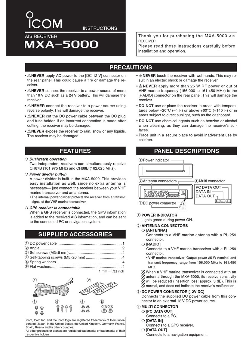
INSTRUCTIONS
AIS RECEIVER
MXA-5000
Thank you for purchasing the MXA-5000 AIS
RECEIVER.
Please read these instructions carefully before
installation and operation.
• RNEVER apply AC power to the [DC 12 V] connector on
the rear panel. This could cause a fire or damage the re-
ceiver.
• RNEVER connect the receiver to a power source of more
than 16 V DC such as a 24 V battery. This will damage the
receiver.
• RNEVER connect the receiver to a power source using
reverse polarity. This will damage the receiver.
• RNEVER cut the DC power cable between the DC plug
and fuse holder. If an incorrect connection is made after
cutting, the receiver may be damaged.
•RNEVER expose the receiver to rain, snow or any liquids.
The receiver may be damaged.
•RNEVER touch the receiver with wet hands. This may re-
sult in an electric shock or damage the receiver.
• R NEVER apply more than 25 W RF power or out of
VHF marine frequency (156.000 to 161.450 MHz) to the
[RADIO] connector on the rear panel. This will damage the
receiver.
• DO NOT use or place the receiver in areas with tempera-
tures below –20°C (–4°F) or above +60°C (+140°F) or in
areas subject to direct sunlight, such as the dashboard.
• DO NOT use chemical agents such as benzine or alcohol
when cleaning, as they can damage the receiver’s sur-
faces.
•Place unit in a secure place to avoid inadvertent use by
children.
r t ye
w
q
PRECAUTIONS
PANEL DESCRIPTIONS
q
wr
e
DC power connector
Antenna connectors Multi connector
Power indicator
PC DATA OUT
DATA IN
DATA OUT
qPOWER INDICATOR
Lights green during power ON.
wANTENNA CONNECTORS
m[ANTENNA]
Connects to a VHF marine antenna with a PL-259
connector.
m[RADIO]
Connects to a VHF marine transceiver with a PL-259
connector.
• VHF marine transceiver: Output power 25 W nominal and
transmit frequency range from 156.000 MHz to 161.450
MHz.
When a VHF marine transceiver is connected with an
antenna through the MXA-5000, its receive sensitivity
will be reduced (Insertion loss: approx. 3 dB). This is
normal, and does not indicate the receive’s malfunction.
eDC POWER CONNECTOR [12V DC]
Connects the supplied DC power cable from this con-
nector to an external 12 V DC power source.
rMULTI CONNECTOR
m[PC DATA OUT]
Connects to a PC.
m[DATA IN]
Connects to a GPS receiver.
m[DATA OUT]
Connects to a navigation equipment.
qDC power cable ............................................................. 1
wAngle.............................................................................. 2
eSet screws (M3×6 mm) .................................................. 4
rSelf-tapping screws (M5×20 mm) .................................. 4
tSpring washers .............................................................. 4
yFlat washers................................................................... 4
1 mm = 1/32 inch
SUPPLIED ACCESSORIES
Icom, Icom Inc. and the Icom logo are registered trademarks of Icom Incor-
porated (Japan) in the United States, the United Kingdom, Germany, France,
Spain, Russia and/or other countries.
All other products or brands are registered trademarks or trademarks of their
respective holders.
mDualwatch operation
Two independent receivers can simultaneously receive
CH87B (161.975 MHz) and CH88B (162.025 MHz).
mPower divider bult-in
A power divider is built-in the MXA-5000.
This provides
easy installation as well, since no extra antenna is
necessary— just connect the receiver between your VHF
marine transceiver and an antenna.
• The internal power divider protects the receiver from a transmit
signal of the VHF marine transceiver.
mGPS receiver is connectable
When a GPS receiver is connected, the GPS information
is added to the received AIS information, and can be sent
to the connected PC or navigation system.
FEATURES
American Communication Systems
Discover the Power of Com m unications
™
TO ORDER –VISIT
http://www.ameradio.com
qAttach the supplied angles to bottom side of the receiver,
and tighten the two supplied screws (M3×6 mm) on each
angle.
Set screws
Angle
wMount the receiver securely with the four supplied screws
(M5×20 mm) to a flat surface which is more than 10 mm
(13/32 inch) thick and can support more than 2 kg (4.4 lb).
Flat washer
Spring washer
Self-tapping
screw
1-1-32 Kamiminami, Hirano-ku, Osaka 547-0003, Japan A-6721H-1EX Printed in Japan
© 2008 Icom Inc.
DATA
OUT
AWG28 to AWG16
PC DATA
OUT
PC DATA OUT
Red
Black
DATA IN
DATA OUT
DATA IN
GPS
receiver
Navigation
equipment
PC
12 V battery
AIS receiver
to antenna
VHF Marine transceiver
Wire information Fuse replacement
Bolting torque
0.22–0.25 N·m
Stripped skin length
6–8 mm
One fuse is installed in the supplied
DC power cable. If a fuse blows or the
receiver stops functioning, track down
the source of the problem, if possible.
Replace the damaged fuse with
properly rated fuse.
PC conncetion
DO NOT use a solid conductor
cable, otherwise the connected
cable may be disconnected.
CAUTION:
NEVER connect a 24 V DC
power source directly. This
will damage the receiver.
This connection is not necessary
if you
have no VHF marine transceiver.
1 5
6 9
1 13
14 25
D-sub 9 Pin
D-sub 25 Pin
Pin 2: Data
Pin 5: Ground
Pin 3: Data
Pin 7: Ground
Less than
2 mm
Fuse rating: 0.5 A
CONNECTIONS
INSTALLATION
SPECIFICATIONS
DGeneral
• Frequency coverage : 161.975 MHz, 162.025 MHz
• Type of emission : 16K0F1D (GMSK)
• Antenna impedance : 50 Wnominal
• Operating temp. range : –20°C to +60°C; –4°F to +140°F
• Power supply requirement : 12 V DC nominal (10.8 V to 15.6 V)
(negative ground)
• Current drain : 0.25 A
• Dimensions (Projections not included)
Without Angle : 132(W) ×34(H) ×155(D) mm
5 3⁄16(W) ×1 11⁄32(H) ×6 3⁄32(D) in
Angle attached : 158(W) ×39(H) ×155(D) mm
6 7⁄32(W) ×1 17⁄32(H) ×6 3⁄32(D) in
• Weight (Approx.)
Without Angle : 400 g (14.1 oz)
Angle attached : 460 g (16.2 oz)
• DATA input interface : IEC61162-1: 2000 (4,800 bps)
Sentence formatters : RMC, GGA, GNS, and GLL
Input level : Less than 2 mA
(When 2 V is applied)
• DATA output interface :
To navigation equipment : IEC61162-2 (38,400 bps)
Sentence formatter : VDM
Output level : 5 V, 40 mA max
RS-422 ballanced type
To PC : Baud rate 38,400 bps
Sentence formatter : VDM
Output level : ±5 V, ±35 mA typical
RS-232C unballanced type
DReceiver
• Sensitivity : 0.35 µV (typical)
• Adjacent channel selectivity : More than 70 dB
• Spurious response : More than 70 dB
• Intermodulation : More than 65 dB
• Hum and noise : More than 40 dB
• Conducted spurious emission
: Less than –57 dBm
All stated specifications are subject to change without notice or obligation.
FOR CLASS B UNINTENTIONAL RADIATORS
This equipment has been tested and found to comply with the limits for a Class B digital device, pursuant
to part 15 of the FCC Rules. These limits are designed to provide reasonable protection against harmful
interference in a residential installation. This equipment generates, uses and can radiate radio frequency
energy and, if not installed and used in accordance with the instructions, may cause harmful interference
to radio communications. However, there is no guarantee that interference will not occur in a particular in-
stallation. If this equipment does cause harmful interference to radio or television reception, which can be
determined by turning the equipment off and on, the user is encouraged to try to correct the interference
by one or more of the following measures:
• Reorient or relocate the receiving antenna.
• Increase the separation between the equipment and receiver.
• Connect the equipment into an outlet on a circuit different from that to which the receiver is connected.
• Consult the dealer or an experienced radio/TV technician for help.
A-6721H-3US
This device complies with Part 15 of the FCC
Rules. Operation is subject to the following two
conditions: (1) this device may not cause harmful
interference, and (2) this device must accept any
interference received, including interference that
may cause undesired operation.
For U.S.A. only
CAUTION!: Changes or modifications to this
device, not expressly approved by Icom Inc.,
could void your authority to operate this device
under FCC regulations.

This manual suits for next models

1

Other Icom Receiver manuals

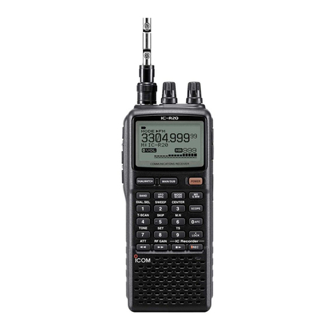
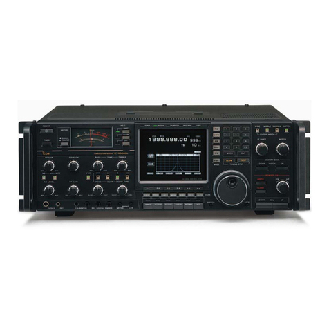
Icom IC-R20 User manual

Icom

Icom IC-R20 User manual

Icom IC-PCR1500 User manual

Icom

Icom IC-PCR1500 User manual

Icom IC-R100 User manual

Icom

Icom IC-R100 User manual

Icom IC-R30 Setup guide

Icom

Icom IC-R30 Setup guide

Icom IC0PCR1000 User manual

Icom

Icom IC0PCR1000 User manual

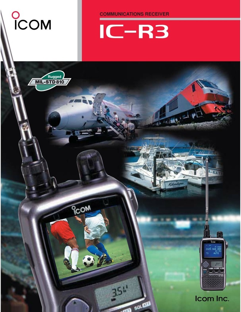
Icom COMMUNICATIONS RECEIVER IC-R3 User manual

Icom

Icom COMMUNICATIONS RECEIVER IC-R3 User manual

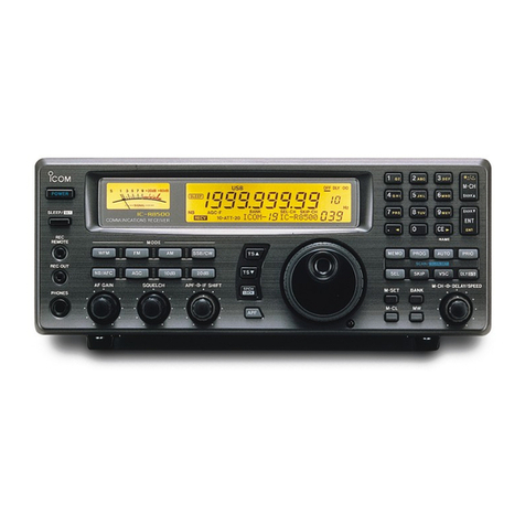
Icom iC- r8500 User manual

Icom

Icom iC- r8500 User manual

Icom IC-R2 User manual

Icom

Icom IC-R2 User manual

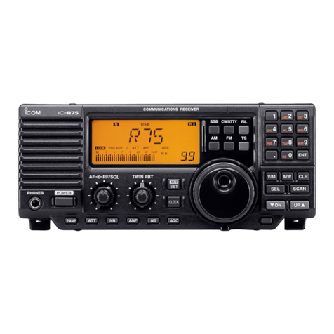
Icom IC-R71A User manual

Icom

Icom IC-R71A User manual

Icom IC-R100 User manual

Icom

Icom IC-R100 User manual

Icom FP-561 User manual

Icom

Icom FP-561 User manual

Icom IC-R9500 User manual

Icom

Icom IC-R9500 User manual

Icom IC-R70 User manual

Icom

Icom IC-R70 User manual

Icom IC-R2 User manual

Icom

Icom IC-R2 User manual

Icom IC-R1 User manual

Icom

Icom IC-R1 User manual

Icom IC-PCR1500 User manual

Icom

Icom IC-PCR1500 User manual

Icom IC-R10 User manual

Icom

Icom IC-R10 User manual

Icom IC-R20 User manual

Icom

Icom IC-R20 User manual

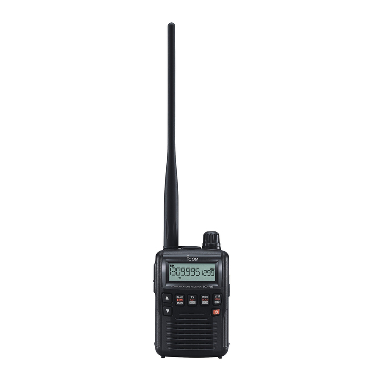
Icom IC-R6 User manual

Icom

Icom IC-R6 User manual

Icom IC-R8600 User manual

Icom

Icom IC-R8600 User manual

Icom IC-R9500 Installation and operating instructions

Icom

Icom IC-R9500 Installation and operating instructions

Icom IC-A25N Installation guide

Icom

Icom IC-A25N Installation guide

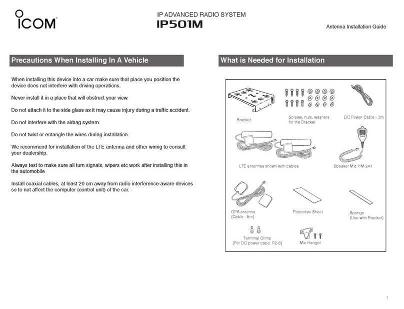
Icom IP501M User manual

Icom

Icom IP501M User manual

Icom mxa- 5000 User manual

Icom

Icom mxa- 5000 User manual

Popular Receiver manuals by other brands

Olson Technology OTPN-3850-SA instruction manual

Olson Technology

Olson Technology OTPN-3850-SA instruction manual

Yamaha HTR-5640 owner's manual

Yamaha

Yamaha HTR-5640 owner's manual

Ten-Tec RX-340 Technical manual

Ten-Tec

Ten-Tec RX-340 Technical manual

Sony STR-AV1070X - Fm Stereo / Fm-am Receiver operating instructions

Sony

Sony STR-AV1070X - Fm Stereo / Fm-am Receiver operating instructions

ab CryptoBox 702T mini user manual

ab

ab CryptoBox 702T mini user manual

Polaris Alpha user guide

Polaris

Polaris Alpha user guide

Hanwha Techwin SBP-329HM quick start guide

Hanwha Techwin

Hanwha Techwin SBP-329HM quick start guide

Topfield TF100T mini user manual

Topfield

Topfield TF100T mini user manual

Yamaha RX V663 - AV Receiver owner's manual

Yamaha

Yamaha RX V663 - AV Receiver owner's manual

SkyLink R4G user manual

SkyLink

SkyLink R4G user manual

Quasonix 3rd Generation RDMS 2760 Installation and operation manual

Quasonix

Quasonix 3rd Generation RDMS 2760 Installation and operation manual

Dart Cheng Communication S810 quick start guide

Dart Cheng Communication

Dart Cheng Communication S810 quick start guide

Ghost Controls AXUR instructions

Ghost Controls

Ghost Controls AXUR instructions

Yamaha R-N602 owner's manual

Yamaha

Yamaha R-N602 owner's manual

Technika TKSTB14 Owner's handbook

Technika

Technika TKSTB14 Owner's handbook

Pioneer MVH-S405BT owner's manual

Pioneer

Pioneer MVH-S405BT owner's manual

enika Rx1 N D quick start guide

enika

enika Rx1 N D quick start guide

Grundig DSR 2410 user manual

Grundig

Grundig DSR 2410 user manual

manuals.online logo
manuals.online logoBrands
  • About & Mission
  • Contact us
  • Privacy Policy
  • Terms and Conditions

Copyright 2025 Manuals.Online. All Rights Reserved.