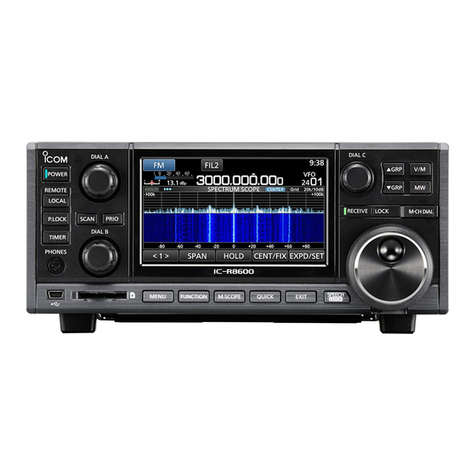
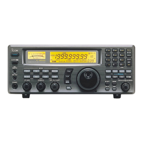
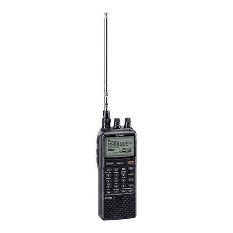
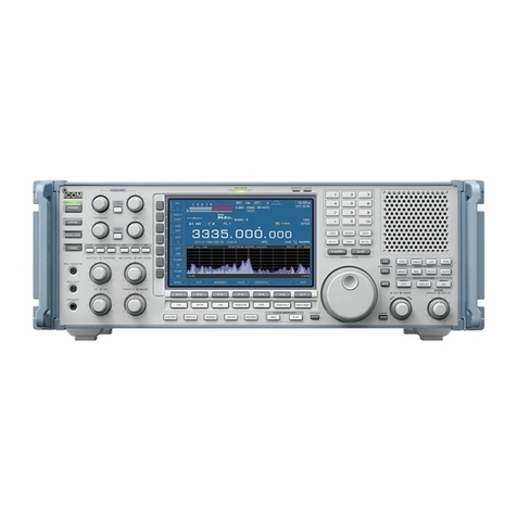
Icom IC-R8600 User manual

INSTRUCTION MANUAL
iR8600
COMMUNICATIONS RECEIVER

i
WORD DEFINITION
RDANGER! Personal death, serious injury or an
explosion may occur.
RWARNING! Personal injury, fire hazard or electric
shock may occur.
CAUTION Equipment damage may occur.
NOTE
Recommended for optimum use. No
risk of personal injury, fire or electric
shock.
EXPLICIT DEFINITIONS
IMPORTANT
READ ALL INSTRUCTIONS carefully completely
before using the receiver.
SAVE THIS INSTRUCTION MANUAL— This
instruction manual contains operating instructions for
the IC-R8600
.
PREFACE
Thank you for choosing this Icom product. The IC-
R8600 COMMUNICATIONS RECEIVER is a wide band
receiver which designed to cover the 10 kHz to
3 GHz range with Icom’s state of the SDR technology.
With proper care, this product should provide you
with years of trouble-free operation. Many hours of
research and development went into the design of
your IC-R8600.
This product includes RTOS “RTX” software, and is licensed according to the software license.
This product includes “zlib” open source software, and is licensed according to the open source software license.
This product includes “libpng” open source software, and is licensed according to the open source software license.
Refer to page I for information on the open source software being used by this product.
TRADEMARKS
Icom, Icom Inc. and the Icom logo are registered trademarks of Icom Incorporated (Japan) in Japan, the United States, the
United Kingdom, Germany, France, Spain, Russia, Australia, New Zealand and/or other countries.
NXDN is a trademark of Icom Incorporated and JVC KENWOOD Corporation.
dPMR and the dPMR logo are trademarks of the dPMR MoU Association.
Microsoft, Windows and Windows Vista are registered trademarks of Microsoft Corporation in the United States and/or other
countries.
All other products or brands are registered trademarks or trademarks of their respective holders.

ii
While ordinary wide band receivers need to have dedicated demodulator circuits for each receive mode, the IC-
R8600 utilizes advanced digital processes that demodulate the incoming signals.
The IF signal is sent to the A/D converter, resulting in digital signal, then is processed by a high-speed FPGA and
DSP to be restored to an analog audio signal.
The received signal is processed to be demodulated according to the receive mode, including not only conventional
analog communications in CW, AM, SSB, FM, WFM and FSK, but also advanced digital communications in D-STAR,
P25, NXDN, dPMR and DCR. This was archived by using Software Dened Radio (SDR) technology.
The AMBE+2™ voice coding Technology embodied in this product is protected by intellectual property rights
including patent rights, copyrights and trade secrets of Digital Voice Systems, Inc. This voice coding Technology is
licensed solely for use within this Communications Equipment. The user of this Technology is explicitly prohibited
from attempting to extract, remove, decompile, reverse engineer, or disassemble the Object Code, or in any other
way convert the Object Code into a human-readable form. U.S. Patent Nos.
#5,870,405, #5,826,222, #5,754,974, #5,701,390, #5,715,365, #5,649,050, #5,630,011, #5,581,656, #5,517,511,
#5,491,772, #5,247,579, #5,226,084 and #5,195,166.
FEATURES
•Covers 10 kHz to 3 GHz for wide band reception
•Receives various digital modes such as
D-STAR, P25 (Phase 1), NXDN, dPMR and DCR
(Digital Convenience Radio)
•12 kHz IF output port for DRM broadcast
•Hi-speed Real-Time Spectrum Scope
•A 4.3 inch touch panel color display
•Multi-function dials for easy settings
•An SD card slot
You can record the received audio, save the receiver
settings, decoded FSK logs and so on, onto an SD card
(user supplied).
•“IP+” Function
The IP Plus function improves 3rd order intercept point
(IP3) performance.
•I/Q baseband signal output port
•Optional external speaker (with integrated power
supply)
SUPPLIED ACCESSORIES
ABOUT THE SDR WIDEBAND RECEIVER CIRCUITS
VOICE CODING TECHNOLOGY
LDifferent types of accessories may be supplied, or may
not be supplied depending on the receiver version.
DC power cable
(3 m: 9.8 ft)
Spare fuse
(3 A/32 V)
Spare fuse
(3 A/125 V)
Speaker plugs
(3.5 mm: 1/8" Stereo) RCA plugs
DC power short connector
FPGA
BPF BPF A/D DSP D/A
1st LO 2nd LO
IF
Demodulator
Double conversion super heterodyne receiver (Example for 30.000000 MHz ~ 1099.999999 MHz)

iii
•FOR CLASS B UNINTENTIONAL RADIATORS:
This equipment has been tested and found to comply
with the limits for a Class B digital device, pursuant
to part 15 of the FCC Rules. These limits are
designed to provide reasonable protection against
harmful interference in a residential installation. This
equipment generates, uses and can radiate radio
frequency energy and, if not installed and used in
accordance with the instructions, may cause harmful
interference to radio communications. However, there
is no guarantee that interference will not occur in a
particular installation. If this equipment does cause
harmful interference to radio or television reception,
which can be determined by turning the equipment
off and on, the user is encouraged to try to correct
the interference by one or more of the following
measures:
• Reorient or relocate the receiving antenna.
• Increase the separation between the equipment
and receiver.
• Connect the equipment into an outlet on a
circuit different from that to which the receiver is
connected.
• Consult the dealer or an experienced radio/TV
technician for help.
DISPOSAL
The crossed-out wheeled-bin symbol on your product, literature, or packaging reminds you that in
the European Union, all electrical and electronic products, batteries, and accumulators
(rechargeable batteries) must be taken to designated collection locations at the end of their work-
ing life. Do not dispose of these products as unsorted municipal waste.
Dispose of them according to the laws in your area.
FCC INFORMATION
WARNING: MODIFICATION OF THIS DEVICE
TO RECEIVE CELLULAR RADIOTELEPHONE
SERVICE SIGNALS IS PROHIBITED UNDER FCC
RULES AND FEDERAL LAW.
CAUTION: Changes or modications to this device,
not expressly approved by Icom Inc., could void
your authority to operate this device under FCC
regulations.
Icom is not responsible for the destruction, damage to, or performance of any Icom or non-Icom equipment, if the
malfunction is because of:
• Force majeure, including, but not limited to, res, earthquakes, storms, oods, lightning, or other natural
disasters, disturbances, riots, war, or radioactive contamination.
• The use of Icom receivers with any equipment that is not manufactured or approved by Icom.

iv
DAbout the touch operation
In the manual, the touch operation is described as
shown below.
Touch
If the display is touched briey, one short beep
sounds.
Touch for 1 second
If the display is touched for 1 second, one
short and one long beep sound.
DTouch screen precautions
• The touch screen may not properly work when the
LCD protection lm or sheet is attached.
• Touching the screen with your nger nails, sharp
topped object and so on, or touching the screen
hard may damage it.
• Tablet PC’s operations such as ick, pinch in and
pinch out cannot be performed on this touch screen.
DTouch screen maintenance
• If the touch screen becomes dusty or dirty, wipe it
clean with a soft, dry cloth.
• When you wipe the touch screen, be careful not to
push it too hard or scratch it with your nger nails.
Otherwise you may damage the screen.
ABOUT THE INSTRUCTIONS
Instruction example
MENU
» SET > Time Set > Date
Detailed instruction
1. Push
MENU
.
Push
• The MENU screen opens.
2. Touch [SET].
MENU screen
• The SET screen opens.
3. Rotate to select “Time Set,” and then
push .
4.
Rotate to select “Date,” then push .
SET screen
This manual is described in the following manner.
“ ” (Quotation marks):
Used to indicate icons, setting items, and screen titles
displayed on the screen.
The screen titles are also indicated in uppercase
letters. (Example: FUNCTION screen)
[ ] (brackets):
Used to indicate keys.
Routes to the set modes and setting screens
Routes to the Set mode, setting screen and the setting
items are described in the following manner.
DATE/TIME screen
DATE screen
5. Touch [+] or [–] to set the date.
6. Touch [SET] to save the entry.

v
TABLE OF CONTENTS
PREFACE................................................................... i
IMPORTANT............................................................... i
TRADEMARKS........................................................... i
EXPLICIT DEFINITIONS............................................ i
FEATURES.................................................................ii
ABOUT THE SDR WIDEBAND RECEIVER CIRCUITS
...ii
VOICE CODING TECHNOLOGY...............................ii
SUPPLIED ACCESSORIES.......................................ii
FCC INFORMATION .................................................iii
ABOUT THE INSTRUCTIONS ..................................iv
DAbout the touch operation ..............................iv
DTouch screen precautions ..............................iv
DTouch screen maintenance ............................iv
TABLE OF CONTENTS............................................. v
PRECAUTIONS....................................................... viii
1 PANEL DESCRIPTION.................................... 1-1
Front panel ....................................................... 1-1
Rear panel........................................................ 1-3
Touch panel display.......................................... 1-4
DMULTI DIAL MENU ( )...................... 1-6
DMENU screen.............................................. 1-6
DQUICK MENU ............................................. 1-6
DFUNCTION screen...................................... 1-7
DFUNCTION items ........................................ 1-7
Keyboard entering and editing ......................... 1-7
DEntering and editing characters .................. 1-7
DKeyboard types ........................................... 1-8
DEntry example ............................................. 1-8
2 INSTALLATION AND CONNECTIONS ........... 2-1
Selecting a location .......................................... 2-1
Heat dissipation................................................ 2-1
For desktop use................................................ 2-1
Grounding......................................................... 2-1
Connecting a DC power supply ........................ 2-1
DPower supply............................................... 2-1
DTurning the receiver's power ON or OFF .... 2-1
Connecting an antenna .................................... 2-2
FSK (RTTY) connections ................................. 2-2
External device connection .............................. 2-3
Adjusting the volume level................................ 3-1
RF gain/SQL level/Audio tone .......................... 3-1
DNoise squelch.............................................. 3-1
DS-meter squelch .......................................... 3-1
DRF gain........................................................ 3-1
3 BASIC OPERATION ........................................ 3-1
Monitor function................................................ 3-1
About the VFO and Memory modes................. 3-1
Selecting the receiving mode ........................... 3-1
Selecting the receiving mode (continued) ........ 3-2
Setting the frequency ....................................... 3-2
DDirectly entering a frequency ...................... 3-2
Changing the Tuning Step................................ 3-2
DAbout the Tuning Step (TS) function ........... 3-2
D
About the Programmable Tuning Step function
. 3-3
DAbout the Auto Tuning Step function........... 3-3
Selecting the antenna....................................... 3-3
Dial/Panel Lock function................................... 3-3
DDial Lock function........................................ 3-3
DPanel Lock function..................................... 3-3
Adjusting Backlight dimmer .............................. 3-4
Fine tuning........................................................ 3-4
DWhen receiving FM, WFM or DIGITAL signal
. 3-4
DWhen receiving FSK signal ......................... 3-4
Selecting meter display ................................... 3-4
DMeter display types ..................................... 3-4
DRX Marker ................................................... 4-1
Spectrum scope screen.................................... 4-1
4 SCOPE OPERATION....................................... 4-1
DUsing the Spectrum Scope ......................... 4-1
DSetting the span .......................................... 4-2
DSetting the range......................................... 4-2
DSearching for the peak signal...................... 4-3
DTouch screen operation............................... 4-3
DMini scope screen ....................................... 4-3
DAdjusting the Reference level ..................... 4-4
DSweep speed............................................... 4-4
DScope set screen.........................................4-5
5 OTHER FUNCTIONS....................................... 5-1
About the Function screen ............................... 5-1
Preamplier ...................................................... 5-1
Attenuator......................................................... 5-1
Selecting the antenna....................................... 5-1
AGC function control ........................................ 5-1
IP Plus function ................................................ 5-2
Notch Filter ....................................................... 5-2
DSetting the notching width and frequency ... 5-2
Using the Digital Twin PBT............................... 5-2
Selecting the digital IF lter .............................. 5-3
DAdjusting the passband width ..................... 5-3
DSelecting the lter shape............................. 5-3
Noise Blanker (NB)........................................... 5-4
Noise Reduction ............................................... 5-4
Duplex operation .............................................. 5-4
AFC function..................................................... 5-5
Receiving in the CW mode............................... 5-5
DSetting the CW pitch control........................ 5-5
DAbout the CW Reverse mode...................... 5-5
Receiving FSK (RTTY) signal .......................... 5-5
DDecoded FSK data display.......................... 5-5
DDecoding FSK signal................................... 5-5
DTurning ON the FSK log .............................. 5-6
DViewing the FSK log contents ..................... 5-7
DTwin Peak Filter........................................... 5-7
DFSK tone and shift setting ........................... 5-7
DAbout the FSK DECODE SET screen......... 5-8
Tone squelch function....................................... 5-9
D.SQL (Digital Squelch) function...................... 5-9

vi
DDigital Code Squelch................................... 5-9
DNetwork Access Code (NAC) ...................... 5-9
DGroup Code (COM ID) and CC ................. 5-10
DRadio Access Number (RAN).................... 5-10
DUser Code (UC)......................................... 5-10
Descrambler function ..................................... 5-10
Decryption function......................................... 5-10
Receive history log ......................................... 5-11
Screen Capture function................................. 5-11
DCapturing a screen.................................... 5-11
DViewing the captured screen..................... 5-11
6 RECORDING AND PLAYING BACK............... 6-1
Recording ......................................................... 6-1
DQuick recording ........................................... 6-1
DNormal recording......................................... 6-1
Playing back ..................................................... 6-1
Operation while playing back ........................... 6-2
Playing back on a PC ....................................... 6-2
Checking the le information ............................ 6-3
Deleting a le.................................................... 6-3
Deleting a folder ............................................... 6-4
PLAYER SET screen........................................ 6-4
RECORDER SET screen ................................. 6-4
7 USING AN SD CARD....................................... 7-1
About the SD card ............................................ 7-1
DSD card’s folder contents ............................ 7-1
Saving data onto the SD card .......................... 7-1
Inserting or removing the SD card.................... 7-1
DInserting....................................................... 7-1
DRemoving (While the receiver is OFF) ........ 7-1
DRemoving (While the receiver is ON).......... 7-1
Formatting an SD card ..................................... 7-2
Saving in the old format.................................... 7-2
Saving the setting data..................................... 7-2
Loading the data les ....................................... 7-3
Deleting a data le............................................ 7-3
Checking SD card information.......................... 7-3
8 Memory channels ........................................... 8-1
Selecting channel group................................... 8-1
DSelecting with /...................... 8-1
DSelecting
on the [GROUP SELECT] screen..8-1
Selecting a memory channel ............................ 8-2
DSelecting with ................................. 8-2
DSelecting with .......................... 8-2
DSelecting using the keypad ......................... 8-2
Writing a memory channel ............................... 8-2
Copying the Memory contents.......................... 8-3
Inserting a blank channel ................................. 8-3
Clearing a memory channel ............................. 8-3
Entering a group/memory name....................... 8-4
DEntering a group name................................ 8-4
DEntering a memory name............................ 8-4
About the MEMORY screen ............................. 8-5
9 SCANS............................................................. 9-1
Scan types........................................................ 9-1
Basic scanning ................................................. 9-1
DVFO scan and Memory scan....................... 9-1
DPriority scan................................................. 9-1
Adjusting the scan speed ................................. 9-1
Setting the Scan Resume function ................... 9-2
DSetting the scan delay timer........................ 9-2
DSetting the Scan Resume function.............. 9-2
Setting the priority interval................................ 9-2
Priority scan...................................................... 9-2
DPriority scan operation................................. 9-2
DMonitoring the Priority channel.................... 9-2
Scan Setting screen ......................................... 9-3
Programmed scan and Fine Programmed scan
..... 9-4
DProgrammed scan operation....................... 9-4
DFine Programmed scan operation............... 9-4
∂F scan............................................................ 9-5
D∂F scan operation....................................... 9-5
DFine ∂F scan operation............................... 9-5
Auto Memory Write scan .................................. 9-6
DAuto Memory Write scan operation............. 9-6
Memory scan and Select Memory scan ........... 9-7
DMemory scan operation............................... 9-7
DSelect Memory scan operation.................... 9-7
DSetting Select Memory channels................. 9-8
D
Canceling the Select Memory channel settings
.. 9-8
Mode select memory scan ............................... 9-9
DSetting the receive mode ............................ 9-9
Setting the skip frequency ............................... 9-9
DSetting the skip frequency........................... 9-9
DCanceling the skip frequency ...................... 9-9
Setting the Temporary Skip ............................ 9-10
Skip channel for memory scan ....................... 9-10
Voice Squelch Control function ...................... 9-11
Tone scan operation ....................................... 9-11
10 CLOCK AND TIMER...................................... 10-1
Setting the Time and Date.............................. 10-1
DSetting date ............................................... 10-1
DSetting time ............................................... 10-1
NTP Time Server............................................ 10-1
DExecute the time synchronization ............. 10-1
DSetting the NTP Server address................ 10-1
Timer .............................................................. 10-2
DSetting the Sleep timer.............................. 10-2
DSetting the Daily timer ............................... 10-2
Timer (continued) ........................................... 10-3
DTimer setting items .................................... 10-3
DAbout the Timer recording......................... 10-3

vii
11 SET MODE..................................................... 11-1
Set mode description...................................... 11-1
DEntering the Set mode .............................. 11-1
Tone Control ................................................... 11-2
Function.......................................................... 11-2
Digital Set ....................................................... 11-4
Connectors ..................................................... 11-5
Network .......................................................... 11-7
Display............................................................ 11-9
Time Set ....................................................... 11-10
SD Card........................................................ 11-10
Others........................................................... 11-10
12 MAINTENANCE............................................. 12-1
Cleaning ......................................................... 12-1
Replacing fuse................................................ 12-1
DDC power cable fuses ............................... 12-1
DCircuitry fuse ............................................. 12-1
Resetting ........................................................ 12-2
DPartial reset ............................................... 12-2
DAll reset ..................................................... 12-2
Touch screen calibration................................. 12-3
Troubleshooting.............................................. 12-4
13 UPDATING THE FIRMWARE ........................ 13-1
General........................................................... 13-1
DAbout updating the rmware ..................... 13-1
DChecking the rmware version.................. 13-1
Preparation..................................................... 13-1
DDownloading the rmware le ................... 13-1
DUnzipping the rmware folder.................... 13-1
Updating the rmware .................................... 13-2
14 SPECIFICATIONS ......................................... 14-1
DGeneral...................................................... 14-1
DReceiver .................................................... 14-1
15 OPTIONS ....................................................... 15-1
Options ........................................................... 15-1
Attaching the MB-123..................................... 15-1
16 CONNECTOR INFORMATION ...................... 16-1
ABOUT THE LICENSES............................................ I
INDEX........................................................................ II

viii
PRECAUTIONS
RDANGER! NEVER operate the receiver near unshielded
electrical blasting caps or in an explosive atmosphere. This
could cause an explosion and death.
RWARNING! NEVER operate the receiver with a headset
or other audio accessories at high volume levels. If you
experience a ringing in your ears, reduce the volume or
discontinue use.
RWARNING! NEVER apply AC power to the [DC13.8V]
socket on the receiver rear panel. This could cause a re or
damage the receiver.
RWARNING! NEVER apply more than 16 V DC to the
[DC13.8V] socket on the receiver rear panel. This could
cause a re or damage the receiver.
RWARNING! NEVER reverse the DC power cable
polarity. This could cause a re or damage the receiver.
RWARNING! NEVER remove the fuse holder on the DC
power cable. Excessive current caused by a short could
cause a re or damage the receiver.
RWARNING! NEVER let metal, wire or other objects
contact the inside of the receiver, or make incorrect contact
with connectors on the rear panel. This could cause an
electric shock or damage the receiver.
RWARNING! NEVER operate or touch the receiver with
wet hands. This could cause an electric shock or damage
to the receiver.
RWARNING! Immediately turn OFF the receiver power
and remove the power cable from the receiver if it emits an
abnormal odor, sound or smoke. Contact your Icom dealer
or distributor for advice.
RWARNING! NEVER put the receiver on an unstable
place where the receiver may suddenly move or fall. This
could cause an injury or damage the receiver.
RWARNING! NEVER operate the receiver during a
lightning storm. It may result in an electric shock, cause a
re or damage the receiver. Always disconnect the power
source and antenna before a storm.
CAUTION: NEVER expose the receiver to rain, snow or
any liquids.
CAUTION: NEVER change the internal settings of the
receiver. This could reduce receiver performance and/
or damage to the receiver. The receiver warranty does
not cover any problems caused by unauthorized internal
adjustments.
CAUTION: NEVER install or place the receiver in a place
without adequate ventilation.
CAUTION: NEVER use harsh solvents such as Benzine
or alcohol when cleaning, as they will damage the receiver
surfaces.
CAUTION: NEVER leave the receiver in areas with
temperatures below –10°C (+14°F) or above +60°C
(+140°F).
CAUTION: NEVER place the receiver in excessively dusty
environments. This could damage the receiver.
DO NOT place the receiver against walls or put anything on
top of the receiver. This may overheat the receiver.
BE CAREFUL! The receiver will become hot when
operating the receiver continuously for long periods of time.
NEVER leave the receiver in an insecure place to avoid use
by unauthorized persons.
Turn OFF the receiver’s power and/or disconnect the DC
power cable when you will not use the receiver for long
period of time.
The display may have cosmetic imperfections that appear
as small dark or light spots. This is not a malfunction or
defect, but a normal characteristic of LCDs.
The IC-R8600 may receive its own oscillated frequency,
resulting in no reception or only noise reception including
on the Spectrum Scope screen, on some frequencies.

1PANEL DESCRIPTION
1-11-1
Front panel
qPOWER KEY (p. 2-1)
Turns the receiver ON (lights blue) or OFF.
wLOCAL KEY (p. 16-2)
Turns OFF the Remote mode.
LIn the Remote mode, all the operations on the panel
except , and are locked.
ePANEL LOCK KEY (p. 3-3)
Locks the controls (lights white) on the front panel.
LHold down for 1 second to turn OFF the display.
rTIMER KEY (p. 10-2)
Turns ON (lights orange) or OFF the Timer function.
LSet the current time to use the Timer function. (p. 10-1)
tHEADPHONE JACK [PHONES] (p. 16-2)
Accepts headphones. (3.5 mm: 1/8 in (d))
y[USB] (mini-B type) PORT (pp. 2-3, 16-1)
Connects to a PC.
• Outputs the decoded FSK (RTTY) or D-STAR data.
• Outputs the demodulated AF signal or 12 kHz IF signal.
• Interface for the optional CS-R8600 or RS-R8600
(future product).
• Interface for the remote control by the CI-V command.
uDIAL B (p. 1-6)
• Rotate to adjust the audio output level.
• Push to display the setting menu, then rotate to adjust
the RF gain (sensitivity), squelch threshold levels or
audio tone (Treble or Bass).
• Hold down to turn ON the Monitor function (the squelch
opens).
iSD CARD SLOT [SD CARD] (pp. 7-1, 7-2)
Accepts an SD card.
oMENU KEY (pp. 1-6, 11-1)
Opens the MENU screens where you can modify
the receiver settings and edit memory channels.
!0 FUNCTION KEY
FUNCTION
(pp. 1-7, 5-1)
Displays the FUNCTION screen where you can
congure various settings.
!1 MINI SCOPE KEY
M.SCOPE
(p. 4-3)
• Push to display the Mini Scope.
• Hold down for 1 second to display the Spectrum Scope.
!2 QUICK KEY
QUICK
(p. 1-6)
Displays the QUICK MENU.
!3 EXIT KEY
EXIT
Exits a setting screen or returns to the previous
screen.
!4 SPEECH/LOCK KEY (p. 3-3)
• Push to announce the receiving frequency and mode.
•
Hold down for 1 second to lock (lights white) .
!5 TENSION ADJUSTER
Adjusts the friction of in 3 steps.
!6 MAIN DIAL
Changes the operating frequency or setting value.
!7 RECEIVE INDICATOR
Lights green while receiving a signal or the squelch
(p. 3-1) is opened.
!8 LOCK INDICATOR (p. 3-3)
Lights white while the is locked by .
This section describes the keys, controls and dials that you use to operate the IC-R8600.
Refer to the pages posted beside each key, control, or dial for details.
q
w
e
r
t
y
u i o !0 !1 !2 !3 !4 !5
!6
!7
!8

1
PANEL DESCRIPTION
1
2
3
4
5
6
7
8
9
10
11
12
13
14
15
16
17
18
19
20
21
1-2
Front panel (Continued)
!9!9
@0
@1
@2@3
@5 @4
@6
!9 MEMORY CHANNEL DIAL KEY (p. 8-2)
Push this key (lights white) then rotate
to change the Memory channel number.
@0 MEMORY WRITE KEY (p. 8-2)
• Push to open the MW MENU screen.
• Hold down for 1 second to write the current receiving
contents (frequency, mode, and so on) to a memory
channel.
@1 VFO/MEMORY KEY (p. 3-1)
• Push to toggle between the VFO and Memory modes,
• Hold down for 1 second to copy the selected memory
channel contents to the VFO.
@2 MEMORY GROUP KEY / (p. 8-1)
Changes the Memory channel group.
@3 DIAL C (p. 1-6)
• Push to display the Multi Dial menu.
• Turn to change the memory channel number.
@4 PRIORITY SCAN KEY (p. 9-2)
Starts or cancels a Priority scan.
LSelect a Memory channel before starting a Priority
scan.
@5 DIAL A (p. 1-6)
• Push to display the scan setting menu, then rotate to
set the Scan speed or Priority scan interval.
@6 SCAN KEY (p. 9-1)
• Push to display the SCAN START screen.
• Hold down for 1 second to start a scan (except Priority
scan).

1PANEL DESCRIPTION
1-3
Rear panel
qDC POWER SOCKET [DC 13.8 V] (pp. 2-1, 16-2)
Connects to the supplied DC power cable.
wDC INPUT JACK [DC IN] (pp. 2-1, 16-2)
Connects to the optional SP-39AD (External speaker with
built-in power adapter) or AD-55NS (Power adapter).
L
Before connecting an SP-39AD or AD-55NS, connect the
supplied DC power short connector to [DC 13.8V] (q).
eGROUND TERMINAL [GND] (p. 2-1)
Connects to ground to prevent electrical shocks
and other problems.
rANTENNA CONNECTOR [ANT1] (N type) (p. 2-2)
Connects to a 10 kHz ~ 3000 MHz antenna.
tANTENNA CONNECTOR [ANT2] (SO-239) (p. 2-2)
Connects to a 10 kHz ~ 30 MHz antenna.
yANTENNA CONNECTOR [ANT3] (RCA) (p. 2-2)
Connects to a 10 kHz ~ 30 MHz antenna.
uAUX JACK [AUX]
A reserved jack. No internal connection.
iEXTERNAL METER JACK [METER]
(pp. 2-3, 16-1)
Connects to an external analog RSSI or squelch
level meter (user supplied).
oREFERENCE SIGNAL INPUT/OUTPUT
CONNECTOR [REF I/O 10MHz] (BNC) (p. 16-1)
Inputs or outputs a 10 MHz reference frequency signal.
!0 IF SIGNAL OUTPUT CONNECTOR
[10.7MHz OUT] (BNC) (p. 16-1)
Outputs a 10.7 MHz IF signal.
!1 I/Q DATA OUTPUT PORT [I/Q OUT] (pp. 2-3, 16-1)
Outputs I/Q data.
LConnect a USB (1.1/2.0 standard) port (B type).
!2
EXTERNAL SPEAKER JACK [EXT-SP] (pp. 2-3, 16-2)
Connects to an optional external speaker SP-39AD
(External speaker with built-in power adapter).
(3.5 mm: 1/8 in (d))
LAccepts a 4~8 Ω speaker.
!3 AF/IF OUTPUT JACK [AF/IF] (pp. 2-3, 16-1)
Outputs the demodulated AF signal, or a 12 kHz IF
signal.
LThe output level is set, regardless of the volume control.
!4
REMOTE CONTROL JACK [REMOTE] (pp. 2-3, 16-2)
Connects to a PC for remote control using CI-V
commands. (3.5 mm: 1/8 in (d))
!5 [USB] (B type) PORT (p. 2-3, 16-1)
Connects to a PC.
• Outputs the decoded FSK (RTTY) or D-STAR data.
• Outputs the demodulated AF signal or 12 kHz IF signal.
• Interface for the optional CS-R8600 or RS-R8600
(future product).
• Interface for the remote control by the CI-V commands.
!6 [MUTE] JACK/[MUTE] SWITCH (pp. 2-3, 16-1)
Used for the Mute function, or Bit Error Rate (BER)
Measurement function. (3.5 mm: 1/8 in (d))
LSlide the switch to the left when you use the
Mute function. The IC-R8600's receive circuitry is
deactivated by the input voltage.
LSlide the switch to the right when you use the BER
Measurement function.
!7 LAN PORT [LAN] (pp. 2-3, 16-1)
Connects to a network to use the functions shown
below.
• Automatic time synchronization.
• Outputs the received signal in
demodulated AF signal
, or
in 12 kHz IF signal, through the network.
• Remotely controlling using the optional RS-R8600
(future product).
o
!0
w
i
t r e
yu
!7
!1 !3!2 !4 !5 q
!6

1
PANEL DESCRIPTION
1
2
3
4
5
6
7
8
9
10
11
12
13
14
15
16
17
18
19
20
21
1-4
Touch panel display
qMODE INDICATOR (p. 3-1)
Displays the selected receive mode.
wVSC INDICATOR (pp. 9-11, 5-10)
Appears while the Voice Squelch Control (VSC)
function is ON.
SCRM:
Appears while the Scrambler function is ON.
ENCR:
Appears while the Encryption function is ON.
e
PASSBAND WIDTH INDICATOR (BW/SFT)
(pp. 5-2, 5-9)
• Graphically displays the digital IF lter passband width
and the shift amount.
• While the Tone/Digital Squelch function is ON, displays
the tone/digital squelch type.
TSQL: Tone squelch COM ID: Common ID
DTCS: Digital tone squelch CC: –
CSQL: Digital code squelch RAN:
Radio access number
NAC: Network access code UC: User code
rIF FILTER INDICATOR (p. 5-3)
Displays the selected IF lter (FIL1, FIL2 or FIL3).
tPREAMP INDICATOR (pp. 1-7, 5-1)
Is displayed while the preampli er is ON.
yMEMORY NAME READOUT (p. 8-5)
Displays the memory name if entered.
uATTENUATOR INDICATOR
(ATT10/ATT20/ATT30) (pp. 1-7, 5-1)
Is displayed while the attenuator is ON.
iIP+ ICON (pp. 1-7, 5-2)
Is displayed while the IP Plus function is ON.
(This screen is only an example.)
oNETWORK CONTROL INDICATOR
Is displayed
while the IC-R8600 is remotely
controlled by the optional RS-R8600 (future
product), through the network.
!0 VOICE RECORDER ICON / (p. 6-1)
Is displayed while recording to indicate the
recording status.
!1 CLOCK READOUT (p. 10-1)
Displays the current local time.
LTouch the readout to display both the current local time
and UTC time.
!2 AFC INDICATOR (p. 5-5)
Is displayed while the Automatic Frequency Control
(AFC) function is ON.
!3 SKIP INDICATOR (pp. 9-9, 9-10)
SKIP: Memory Skip
P
SKIP: Program Skip
!4 OPERATING MODE INDICATOR (p. 3-1)
VFO
: VFO mode
MEMO
: Memory mode
!5 MEMORY CHANNEL READOUT (pp. 3-1, 8-2)
Displays the selected memory channel number.
!6 BLANK MEMORY CHANNEL INDICATOR (p. 8-3)
Is displayed when the selected memory channel is blank.
!7 MEMORY CHANNEL GROUP INDICATOR (p. 8-1)
00~99: Memory channel group number
A: Auto memory write group
S: Scan skip group
P: Programmable scan edge group
q e rtuio!0 !1
y
!3
!4
!5
!6
w
!7
!2

1PANEL DESCRIPTION
1-5
Touch panel (Continued)
(This screen is only an example.)
!8 PRIORITY INDICATOR (p. 9-2)
Is displayed
during a Priority scan.
LBlinks while the squelch is forced to open during a
Priority scan. (p. 9-3)
!9 TUNING STEP INDICATOR (p. 3-2)
Displays the currently selected tuning step.
LIf the tuning step is set by the programmable tuning
step, "◄" is displayed by the indicator.
@0 FUNCTION SCREEN
Displays the operating parameters, modes,
frequencies and indicators, depending on your
selections.
@11 FUNCTION GUIDES
Displays the currently accessible function.
@2
RECEIVED SIGNAL STRENGTH INDICATOR (p. 3-4)
Displays the absolute received signal strength in
terminated or open load measurement.
@3 SIGNAL METER (p. 3-5)
Indicates the signal strength in S-meter/dBµ/
dBµ(EMF)/dBm.
@4 RF GAIN (RFG) (p. 3-1)
Is displayed
when the RF gain is set to less than
100% to indicate that the RF gain is reduced.
@5 TUNING INDICATOR (p. 3-4)
Displays the detuned level in the FM, WFM, FSK
and DIGITAL modes.
@6 OVERFLOW (OVF) INDICATOR (pp. 3-1, 5-1)
Is displayed when an excessively strong signal
is received. (Normally, "S" is displayed to in the
S-Meter mode)
@7 AGC INDICATOR (pp. 1-7, 5-1)
Displays the selected AGC time constant setting.
(AGC-F: Fast, AGC-M: Mid, AGC-S: Slow or AGC-OFF: OFF).
@8
ANTENNA INDICATOR (p. 3-3, 5-1)
Displays the selected antenna (ANT1, ANT2 or ANT3) only
when the frequency is set to 10 kHz ~ 29.999999 MHz.
@9 NOTCH INDICATOR (AN/MN) (pp. 1-7, 5-2)
Is displayed while the Notch function is ON. (AN:
Auto Notch or MN: Manual Notch)
#0 NOISE BLANKER INDICATOR (NB) (pp. 1-7, 5-4)
Is displayed while the Noise Blanker function is ON.
#1 NOISE REDUCTION INDICATOR (NR) (p. 1-7, 5-4)
Is displayed while the Noise Reduction function is ON.
#2 TWIN PEAK FILTER INDICATOR (TPF) (p. 5-7)
Is displayed while the Twin Peak Filter function is ON.
#3 DUP INDICATOR (DUP–/DUP+) (pp. 1-7, 5-4)
Is displayed while in the Duplex mode.
#4 TS INDICATOR ("▼") (p. 3-2)
Is displayed when the TS function is on. The
frequency changes according to the tuning step set
in TUNING STEP INDICATOR (
!9
).
LTouch kHz digit to turn OFF the TS function.
#5 MONITOR INDICATOR (MONI) (p. 3-1)
Appears while the Monitor function is ON.
@9 #0 #1 #2 #3 #5
@8
@7
@5
!8
!9
@6
@0
@1
@4
@2
@3
#4

1
PANEL DESCRIPTION
1
2
3
4
5
6
7
8
9
10
11
12
13
14
15
16
17
18
19
20
21
1-6
Touch panel (Continued)
zPush to open the Multi Dial menu.
Push again to close the menu.
zWhile the Multi Dial menu is opened, touch the
desired item and rotate to set the desired
value or function.
DMENU screen
zPush to open the MENU screen.
LThe menu items differ, depending on the selected receive
mode.
DMULTI DIAL MENU ( )
• When rotating .
• When rotating .
• When pushing .
LTouch to select an item, then rotate .
• When pushing .
LTouch to select an item, then rotate .
• When holding down for 1 second.
LTouch an item.
• When holding down for 1 second.
• The Monitor function is turned ON ([RECEIVE] lights green).
LRelease to turn OFF the Monitor function.
DQUICK MENU
zPush to open the QUICK MENU.
LThe items differ, depending on the operating condition.
QUICK MENU example
Touch the key to
turn ON and OFF
Multi dial menu items
Displayed items differ, according to the selected
receive mode.
FM/WFM AM/S-AM SSB CW
AFC*1 PBT1 PBT1 PBT1
PBT2 PBT2 PBT2
VSC*1 VSC*1 VSC*1 CW PITCH
BACKLIGHT BACKLIGHT BACKLIGHT BACKLIGHT
FSK DIGITAL NB*2NR*2
PBT1 AFC*1 LEVEL LEVEL
PBT2 DEPTH
TPF*1 WIDTH
BACKLIGHT BACKLIGHT
NOTCH*2
POSITION
WIDTH*1
*1Touch to turn the function ON or OFF.
*2 Displayed when you touch the item on the FUNCTION
screen for 1 second.

1PANEL DESCRIPTION
1-7
Touch panel (Continued)
DFUNCTION screen
zPush
FUNCTION
to open the FUNCTION screen.
LTo close the FUNCTION screen, push
EXIT
.
Function
name
Selected
option
Lights blue
in use
DFUNCTION items
zTouch an item to change its setting.
*1Touch for 1 second to open its function menu.
*2Touch to open its function menu.
FUNCTION OPTION
ANT ANT1, ANT2 or ANT3
P.AMP OFF or ON
ATT OFF, 10dB, 20dB or 30dB
IP+ OFF or ON
TONE*1OFF, TSQL or DTCS
TONE/SHIFT*2FSK RX Frequency, FSK Tone
Frequency or FSK Shift width
D.SQL*1
D-STAR: OFF or CSQL
P25: OFF or NAC
dPMR: OFF, COM ID or CC
NXDN: OFF or RAN
DCR: OFF or UC
AGC*1FAST, MID or SLOW
NOTCH*1OFF, AN or MN
NB*1OFF or ON
SCRAM*1OFF or ON
ENCRYP*1OFF or ON
NR*1OFF or ON
DUP*1OFF, DUP– or DUP+
Category
Edit items
Total
character
number
Selectable characters
MEMORY
GROUP NAME
MEMORY NAME 16
A to Z, a to z, 0 to 9, (space), @
% & # + - = [ ] / ( ) : ; ˄ ! ? < > . ,
DISPLAY OPENING COMMENT 10
A to Z, 0~9, (space), / @ - .
SD card
FILE NAME*
15
A to Z, a to z, 0 to 9, (space),
@ % & # + - = [ ] / ( ) : ; ^ ! ? < >
, . " $ ' * \ _ ` { } | ~
TIME NTP SERVER ADDRESS 64
A to Z, a to z, 0~9, (space), - .
NETWORK
NETWORK NAME
15
A to Z, 0 to 9, (space), ! " # $ %
& ( ) + , - . ; = @ [ ] ^ _ ' { } ~
NETWORK RADIO NAME
16
A to Z, a to z, 0 to 9, (space), ! "
# $ % & ' ( ) * + , - . / : ; < > = ?
@ [ ] ^ _ ` { } | ~
NETWORK USER1 ID
NETWORK USER2 ID
16
A to Z, a to z, 0 to 9, (space), ! "
# $ % & ' ( ) * + , - . / : ; < > = ?
@ [ ] ^ _ ` { } | ~
NETWORK USER1 PASSWORD
NETWORK USER2 PASSWORD
16
A to Z, a to z, 0 to 9, (space), ! "
# $ % & ' ( ) * + , - . / : ; < > = ?
@ [ ] ^ _ ` { } | ~
*Illegal characters " / : ; * < > "
Keyboard entering and editing
DEntering and editing characters
You can enter and edit characters in the items in the
following table.

1
PANEL DESCRIPTION
1
2
3
4
5
6
7
8
9
10
11
12
13
14
15
16
17
18
19
20
21
1-8
DEntry example
Example: Entering memory name "MAIN CHANNEL."
1. Open the MEMORY screen.
MENU
» MEMORY
2. Rotate to select the channel you want to
enter a name in.
3.
Push .
4. Touch “Edit Name.”
5. Touch for 1 second to select the upper case
entry mode.
6. Enter a name of up to 16 characters, then touch [ENT].
• The entered name is displayed.
DKeyboard types
You can select the Full Keyboard or Tenkey in
“Keyboard Type” in the QUICK MENU.
1. When the keypad is opened, push .
2. Touch to select the keyboard type.
MENU
» SET > Function > Keyboard Type
InformationL
You can also select the Keyboard type in the Set mode.
Keyboard entering and editing (Continued)
Enters a space
Cursor
Moves the cursor
forward
Switched to Full Keyboard Switched to Tenkey

2INSTALLATION AND CONNECTIONS
2-12-1
Selecting a location
For desktop use
Select a location for the receiver that allows adequate
air circulation, free from extreme heat, cold or
vibrations, and other electromagnetic sources.
An improper location may damage the receiver.
Never place the receiver in areas such as:
• Temperatures below –10°C (+40°F) or above +60°C
(+140°F).
• Unstable place slope or vibrate.
• In direct sunlight.
• High humidity and temperature.
• Dusty environments.
• Noisy environments.
DPower supply
You can use any of the power sources listed below.
• 13.8 V DC power supply (User supplied)
• Optional SP-39AD
(External speaker with built-in power supply)
• Optional AD-55NS (Power adapter)
DTurning the receiver's power ON or OFF
zPush to turn ON the power.
zHold down until the "POWER OFF..." is
displayed.
The receiver has a stand for desktop use.
zPull the stand until it locks in place.
CAUTION: NEVER carry the receiver by holding the stand,
dials, controls and so on. This may damage them.
Heat dissipation
Grounding
To prevent electrical shock, interfere
from other electric devices and other
problems, ground the receiver using
the ground terminal [GND] on the rear
panel.
For best results, connect a heavy
gauge wire or strap to a long ground
rod. Make the distance between the
[GND] terminal and ground as short as
possible.
RWARNING! NEVER connect the [GND] terminal
to a gas or electric pipe, since the connection could
cause an explosion or electric shock.
• DO NOT place the receiver against walls, or put
anything on top of the receiver. This may block airow.
• NEVER install the receiver in a place without
adequate ventilation. Heat dissipation may be
reduced, and the receiver may be damaged.
Stand
Connecting a DC power supply
+
_
IC-R8600
AC outlet
When disconnecting,
rmly push down the
locking tab and then pull
the connector out of the
socket.
AC outlet
Short connector:
Connect when
SP-39AD or
AD-55NS is used.
AC outlet DC power cable
AD-55NS (Option)
SP-39AD
(Option)
Speaker
cable
Supplied DC power cable
Red
External power supply
(User supplied)
Black

2
INSTALLATION AND CONNECTIONS
1
2
3
4
5
6
7
8
9
10
11
12
13
14
15
16
17
18
19
20
21
2-2
InformationL.
Antenna is a very important element in receiving
signal. Use the antenna and coaxial cable of
appropriate impedance.
Connecting an antenna
FSK (RTTY) connections
The receiver has a built-in FSK (RTTY) decoder.
Connect the IC-R8600 and a PC that has an FSK (RTTY) software (user supplied) installed through the USB port,
to decode the FSK signal. Refer to the software application’s instruction manual for setup details.
LIcom does not guarantee performance of the application software, PC, network device or network settings.
• You can change the FSK output port on the MENU screen.
• You can download the USB driver and installation guide from the Icom website.
http://www.icom.co.jp/world/support/download/rm/index.html
MENU
» SET > Connectors > USB (Front)
MENU
» SET > Connectors > USB (Rear)
To the USB port Type A
IC-R8600
Type B
A user supplied A/B USB cable
PC with RTTY
software installed
To a USB port
When you use a long wire antenna for short wave
bands, use one as long as possible (at least 10 m,
32.8 ft).
0.01 MHz ~ 30 MHz (500 Ω)
0.01 MHz ~ 30 MHz (50 Ω) 0.01 MHz ~ 3000 MHz (50 Ω)
Wire dipole antenna Yagi antenna
Discone antenna
Grounding prevents
electrical shock
and another problems.
Folded-dipole antenna (T2FD type)
Long wire antenna
ANT 3 jack (RCA type)
ANT 2 connector (SO-239) ANT 1 connector (N type)
GND terminal

2INSTALLATION AND CONNECTIONS
2-3
External device connection
[DC 13.8 V] DC power connector
(p. 16-2)
[DC IN] jack (p. 16-2)
[LAN] port (p. 16-1)
[AF/IF] jack
(3.5 mm: 1/8 in (d))
(p. 16-1)
[METER] jack (p. 16-1)
[I/Q OUT] port
(USB B type)
(p. 16-1)
[MUTE] jack
(3.5 mm: 1/8 in (d))
(p. 16-1)
MUTE switch (p. 16-1)
CAB-1258
(Supplied)
OPC-1605 (Supplied)
Connect when an SP-39AD
or AD-55NS is used.
Connects the optional SP-
39AD or AD-55NS.
Connects to a network to use
the functions shown below.
• Automatic time synchronization.
• Outputs the demodulated audio
signal or 12 kHz IF signal to the
network.
• Remote control using the optional
RS-R8600 (future product).
Outputs the demodulated audio signal or 12 kHz IF
signal to the network.
Outputs the voltage that
represents the received signal
strength or squelch levels to an
external meter.
Outputs the In phase/
Quadrature (I/Q) data.
Inputs the Mute control signal.
Used for the Bit Error Rate (BER) measurement
function.
[REMOTE] jack (p. 16-2)
(3.5 mm: 1/8 in (d))
[EXT-SP]
(External speaker) jack
(p.
16-2
) (3.5 mm: 1/8 in (d))
Connects the optional
SP-39AD or SP-23.
[USB] port (p. 16-1)
LMini-B type on the front panel, B type
on the rear panel.
• Outputs the decoded FSK (RTTY) or
D-STAR data to the PC.
• Outputs the demodulated audio or
12 kHz IF signal to the PC.
• Remote control operation using the
optional RS-R8600 (future product).
• Programing using the optional CS-
R8600.
Accepts headphones with 8 ~ 16 Ω
impedance.
• Outputs more than 50 mW into an 8 Ω load.
• The volume level may differ, depending
on the headphones.
[PHONES] Headphones (p. 16-2)
LIcom does not guarantee the performance of the PC, network device or network settings.
Remotely controls the receiver, using the CI-V
commands.
LRefer to the Icom web site for the CI-V
commands.
http://www.icom.co.jp/world/support/download/Manual
(3.5 mm: 1/8 in (d))
Other manuals for IC-R8600
3
Table of contents
Other Icom Receiver manuals

Icom
Icom IC-R30 Setup guide

Icom
Icom iC- r8500 Installation and operating instructions

Icom
Icom iC- r8500 User manual

Icom
Icom IC-R5 User manual

Icom
Icom COMMUNICATIONS RECEIVER IC-R3 User manual

Icom
Icom IC-R9000L User manual

Icom
Icom IC-R75 User manual

Icom
Icom IC-A25N Installation guide

Icom
Icom IC-R71 User manual

Icom
Icom IC-R100 User manual

Icom
Icom IC-R30 Setup guide

Icom
Icom IC-R20 User manual

Icom
Icom IC-751A User manual

Icom
Icom IC-R7100 User manual

Icom
Icom IC-R6 User manual

Icom
Icom IC-R70 User manual

Icom
Icom iC- r8500 User manual

Icom
Icom COMMUNICATION RECEIVER IC PCR100 User manual

Icom
Icom iC- r8500 User manual

Icom
Icom IC-RX7 User manual