manuals.online logo
Brands
  1. Home
  2. •
  3. Brands
  4. •
  5. Icom
  6. •
  7. Repeater
  8. •
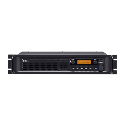
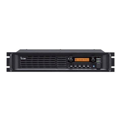
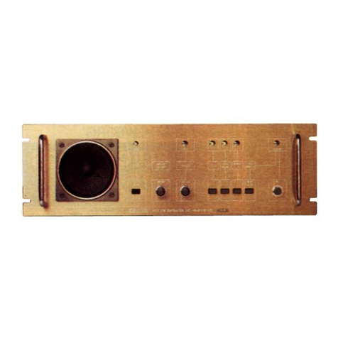
  9. Icom IC-FR5200H User manual

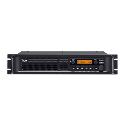
Icom IC-FR5200H User manual

–4 –
–1 –
Thank you for choosing this Icom product. READ ALL
INSTRUCTIONS carefully and completely before us-
ing this product.
INSTRUCTIONS
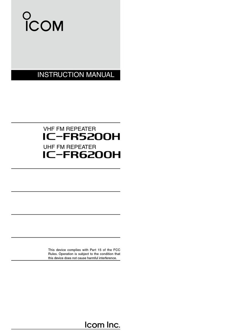
VHF REPEATER
Iç-FR6200H
UHF REPEATER
Iç-FR5200H
A-7189D-2EX-qPrinted in Japan
© 2014–2017 Icom Inc.
1-1-32 Kamiminami, Hirano-ku, Osaka 547-0003, Japan
OPTIONS
• SP-35/SP-35L external speakers
Input impedance : 4 ø
Maximum input power : 7 W
• HM-152 hand microphone
• SM-26 desktop microphone
Some options may not be available in some countries. Please
ask your dealer for details.
CONNECTION
SUPPLIED ACCESSORIES
Handles
DC power cable
For the handles installation
Spacers Allen wrench
Screws
Function name
stickers*1
KEYSEAL
Used for labelling the program-
mable function keys according
to their assinged functions.
*
1
Spare fuse (FGB01 30 A)
Rack
This instruction sheet includes some functions that are us-
able only when they are preset by your dealer. Ask your deal-
er for details.
FOREWORD
ACC
RX TX
LAN BUS-2 BUS-1
FUSE
FUSE
DC INPUT
SPEAKER
GND + –
¬
¬
AC outlet
DC power
cable
NXDN: 13.6 V
dPMR: 13.2 V
(at least 20 A)
Black
_
Red
+
DC power supply*1
*1Purchase separately.
*2See the illustration to the left for the PC console connection
through a Hub (NXDN).
PC console connection (only for NXDN)
To an RX antenna*1To a TX
antenna*1
EXTERNAL SPEAKER*1
SP-35/SP-35L
Connect a 4 øexternal speaker.
ACC CONNECTOR
Used for external equipment
control.
CAT-5 straight cable*1
Repeater
LANBUS-2 BUS-1
LANBUS-2 BUS-1
LANBUS-2 BUS-1
// only for the NXDN version //
The illustration to the right
describes one example of a
connection for trunking mode
operation.
Up to 30 repeaters can be
daisy-chained.
To a [LAN] port of the
IC-FC5000E (dPMR) or a
PC console through a
Hub or a router (NXDN)*2.
IF
PC console*1
To an Ethernet port
Hub*1
To the [LAN] connector
of the repeater
DRear panel connection
FUSE REPLACEMENT
If a fuse blows or the repeater stops functioning, try to find
the source of the problem, and then replace the damaged
fuse with a new rated one.
❑Fuse rating: 30 A
USE only a 30 A fuse.
Icom, Icom Inc. and the Icom logo are registered trademarks of Icom Incor-
porated (Japan) in Japan, the United States, the United Kingdom, Germany,
France, Spain, Russia, and/or other countries.
dPMR and the dPMR logo are trademarks of the dPMR MoU Association
NXDN is a trademark of Icom Incorporated and JVC Kenwood Corporation.
All other products or brands are registered trademarks or trademarks of their
respective holders.
Icom is not responsible for the destruction, damage to, or
performance of any Icom or non-Icom equipment, if the
malfunction is because of:
• Force majeure, including, but not limited to, fires, earth-
quakes, storms, floods, lightning, other natural disasters,
disturbances, riots, war, or radioactive contamination.
• The use of Icom transceivers with any equipment that is
not manufactured or approved by Icom.
The crossed-out wheeled-bin symbol on your
product, literature, or packaging reminds you
that in the European Union, all electrical and
electronic products, batteries, and accumula-
tors (rechargeable batteries) must be taken to
designated collection locations at the end of
their working life.
Do not dispose of these products as unsorted municipal
waste. Dispose of them according to the laws in your area.
DISPOSAL
• Grounding
To prevent electrical shock, television interfer-
ence (TVI), broadcast interference (BCI) and
other problems, ground the repeater using the
GROUND [GND] terminal on the rear panel.
For best results, connect a heavy gauge wire or strap to a
long ground rod. Make the distance between the [GND] ter-
minal and ground rod as short as possible.
RWARNING! NEVER connect the [GND] terminal to a
gas or electric pipe, since the connection could cause an
explosion or electric shock.
• Power supply
Make sure the repeater’s power is OFF when connecting a
DC power cable.
CAUTION: Voltages greater than 16 V DC will damage the
repeater. Check the source voltage before connecting the
power cable.
• Antenna
For repeater communications, an antenna is a critical com-
ponent, along with output power and sensitivity. Select
antenna(s), such as a well-matched 50 øantenna, and feed-
line. A 1.5:1 or better Voltage Standing Wave Ratio (VSWR)
is recommended for a desired band. Of course, the transmis-
sion line should be a coaxial cable.
If you want to connect only one antenna for both transmission
and reception, use a third-party duplexer.
CAUTION: Protect the repeater from lightning by using a
lightning arrestor.
NOTE: There are many publications that describe proper
antennas and their installation. Check with your local dealer
for more information and recommendations.
–2 – – 3 –
PANEL DESCRIPTION PANEL DESCRIPTION (Continued)
P
0
P
1
P
2
P
3
P
4
qw
u yi
Function
display
Speaker
t
r
e
qVOLUME CONTROL [VOLUME]
Rotate to adjust the audio output level.
wSELECTOR DIAL [SELECT]
Rotate to adjust the squelch threshold level, or select an
operating channel (depending on the presetting).
ePOWER INDICATOR [PWR]
Lights green at ‘A’ module’s indicator while the repeater
power is ON.
rTRANSMIT INDICATOR [TX]
Lights red at ‘A’ module's indicator while transmitting.
tBUSY INDICATOR [BUSY]
Lights green at ‘A’ module’s indicator while receiving a
signal or when the squelch is open.
y
MICROPHONE CONNECTOR [MIC]
Connect an optional microphone.
CAUTION: DO NOT detach the [MIC] connector cover
when optional microphone is not in use to prevent dust
from entering.
uPOWER SWITCH [POWER]
➥Push to turn ON the power.
➥Hold down for 3 seconds to turn OFF the power.
iDEALER-PROGRAMMABLE KEYS
Desired functions can be independently preset by your
dealer.
Ask your dealer for details.
qD-SUB 25-PIN [ACC]
Connects an external unit.
Ask your dealer for details.
w
EXTERNAL SPEAKER CONNECTOR [SPEAKER]
Connects the optional SP-35 or SP-35L.
eRECEIVE ANTENNA CONNECTOR [RX]
Connects a receive antenna (impedance: 50 ø) and in-
puts received signals.
rTRANSMIT ANTENNA CONNECTOR [TX]
Connects a transmit antenna (impedance: 50 ø) and out-
puts transmitting signals.
tLAN CONNECTOR [LAN]
For an Ethernet connection, connect the repeater to an Eth-
ernet [LAN] port of a PC console, through a Hub or a router
(NXDN), or to the [LAN] port of the IC-FC5000E (dPMR).
// only for the NXDN version //
In the trunking mode operation, the repeater at one end of
the chain must be connected. You can control the repeater
and all others in the chain from the PC console.
// only for the dPMR version //
In the trunking mode operation, connect to the [LAN] port of
the IC-FC5000E.
y BUS CONNECTORS [BUS-1]/[BUS-2]
// only for the NXDN version //
For data communication between controllers in the trunk-
ing mode operation, you can use either [BUS-1] or
[BUS-2]. Through the connectors, the controllers can be
“daisy-chained” together, and form a network that can
pass the trunking and other data among the controllers.
u FUSE HOLDER
See page 1 to replace a damaged fuse.
i GROUND TERMINAL [GND]
Connect this terminal to ground to prevent electrical
shocks, TVI, BCI, and other problems.
See page 4 for the grounding details.
o DC POWER CONNECTOR [DC INPUT]
Connects a supplied DC power cable from this connector
to an external 13.6 V (NXDN) or 13.2 V (dPMR) DC power
supply (purchase separately).
See page 4 for the connection details.
qw er
tu
oi
* only for the NXDN version
y
*
ACC
RX TX
LANBUS-2BUS-1
FUSE
FUSE
DC INPUT
SPEAKER
GND
+–
¬
¬
IF
DFront panel DRear panel
ICOM Inc.
qwerty
DFunction display
q SIGNAL STRENGTH INDICATOR
Displays the relative receive signal strength level.
w LOW POWER INDICATOR
Displayed when the low output power is selected.
e AUDIBLE INDICATOR
Displayed when a channel is in the ‘audible’ (unmute)
mode.
r COMPANDER INDICATOR
Displayed when the compander function is activated.
t SCRAMBLER/ENCRYPTION INDICATOR
Displayed when the Voice Scrambler or the Encryption
function is activated.
y CHARACTER READOUT
Displays a variety of texts or codes.
INSTALLATION
DInstalling handles to the repeater
The supplied handles are used to mount the repeater into
the supplied rack. The handles can be installed to the re-
peater’s front panel.
q
Attach the supplied handles to both sides of the repeater's
front panel with the spacers, then tighten the screws as
described below.
P
0
P
1
P
2
P
3
P
4
Handle
Spacer
Screw
w
The completed installation should look like as described
below.
P
0
P
1
P
2
P
3
P
4

This manual suits for next models

1

Other Icom Repeater manuals

Icom ID-RP1 User manual

Icom

Icom ID-RP1 User manual

Icom C RP1520 User manual

Icom

Icom C RP1520 User manual

Icom IC-FR3000 Series User manual

Icom

Icom IC-FR3000 Series User manual

Icom ID-RP2C User manual

Icom

Icom ID-RP2C User manual

Icom IC-FR5000 Series User manual

Icom

Icom IC-FR5000 Series User manual

Icom iC-FR5000 User manual

Icom

Icom iC-FR5000 User manual

Icom IC-RP1520 User manual

Icom

Icom IC-RP1520 User manual

Icom FR5000 Operating instructions

Icom

Icom FR5000 Operating instructions

Icom ID-RP2010V User manual

Icom

Icom ID-RP2010V User manual

Icom iC-FR5000 User manual

Icom

Icom iC-FR5000 User manual

Icom IC-RP2210 Service manual

Icom

Icom IC-RP2210 Service manual

Icom FR3000 User manual

Icom

Icom FR3000 User manual

Icom UR-FR5000 User manual

Icom

Icom UR-FR5000 User manual

Icom IC-RP4020 User manual

Icom

Icom IC-RP4020 User manual

Icom FR9020 11 User manual

Icom

Icom FR9020 11 User manual

Icom id- rp2 User manual

Icom

Icom id- rp2 User manual

Icom IC-FR9020 User manual

Icom

Icom IC-FR9020 User manual

Icom IC-FR4000 Series User manual

Icom

Icom IC-FR4000 Series User manual

Icom IC-UR8050 User manual

Icom

Icom IC-UR8050 User manual

Icom IC-RP1620 User manual

Icom

Icom IC-RP1620 User manual

Icom iFR5000 User manual

Icom

Icom iFR5000 User manual

Icom IC-RP1520 User manual

Icom

Icom IC-RP1520 User manual

Icom id- rp2 User manual

Icom

Icom id- rp2 User manual

Icom IC-FR5100 Series User manual

Icom

Icom IC-FR5100 Series User manual

Popular Repeater manuals by other brands

Serveredge 4K2K user manual

Serveredge

Serveredge 4K2K user manual

Black Box DKM SERIES user manual

Black Box

Black Box DKM SERIES user manual

wattstopper MRR2 installation instructions

wattstopper

wattstopper MRR2 installation instructions

Cirronet HN-2010 user guide

Cirronet

Cirronet HN-2010 user guide

Fritz! 1750E Installation and operation

Fritz!

Fritz! 1750E Installation and operation

DKS 2332-080 quick guide

DKS

DKS 2332-080 quick guide

FeinTech VMR00200 manual

FeinTech

FeinTech VMR00200 manual

Kenwood TH-D72A manual

Kenwood

Kenwood TH-D72A manual

Insignia NS-HZ341 Quick setup guide

Insignia

Insignia NS-HZ341 Quick setup guide

Danfoss CF-RU instruction manual

Danfoss

Danfoss CF-RU instruction manual

Nikrans BD-5000-Voice 3G PRO quick start guide

Nikrans

Nikrans BD-5000-Voice 3G PRO quick start guide

CYP CPRO-11SR Operation manual

CYP

CYP CPRO-11SR Operation manual

Vertex Standard VXR-9000 Series Service manual

Vertex Standard

Vertex Standard VXR-9000 Series Service manual

Rocstor Y10G003-B1 user manual

Rocstor

Rocstor Y10G003-B1 user manual

ADTRAN 1223445L2 Job aid

ADTRAN

ADTRAN 1223445L2 Job aid

Nikrans LCD-500GD installation guide

Nikrans

Nikrans LCD-500GD installation guide

CaryMart 0010002 manual

CaryMart

CaryMart 0010002 manual

B+B SmartWorx 232OPDR quick start guide

B+B SmartWorx

B+B SmartWorx 232OPDR quick start guide

manuals.online logo
manuals.online logoBrands
  • About & Mission
  • Contact us
  • Privacy Policy
  • Terms and Conditions

Copyright 2025 Manuals.Online. All Rights Reserved.