Icom IC-7800 User manual

1-15
■Screen menu arrangement
The following screens can be selected from the start
up screen. Choose the desired screen using the fol-
lowing chart.
Pushing [EXIT/SET] several times returns to the start
up screen. See p. 12-3 for set mode arrangement.
1
PANEL DESCRIPTION
• Spectrum scope screen (p. 5-2)
• Voice recorder screen (p. 7-3)
• RTTY decoder screen (p. 4-13)
• Memory keyer screen (CW mode; p. 4-8)
• Memory channel screen (p. 8-3)
• PSK31 decoder screen (p. 4-21)
• Scan screen (VFO mode; p. 9-4)
• Scan screen (Memory mode; p. 9-6)
• Set mode menu screen (p. 12-2)

4-5
DDConvenient functions for transmit
DDAbout CW reverse mode
CW-R (CW Reverse) mode uses the opposite side
band to receive CW signals.
Use when interfering signals are near a desired signal
and you want to use CW-R to reduce the interference.
➥During CW mode, push [CW] to select CW and CW-
R mode.
DDAbout CW pitch control
The received CW audio pitch and CW side tone can
be adjusted to suit your preference (from 300 to
900 Hz in 5 Hz steps). This does not change the oper-
ating frequency.
➥Rotate [CW PITCH] to suit your preference.
• Adjustable within 300 to 900 Hz in 25 Hz steps.
DDCW side tone function
When the transceiver is in the receive condition (and
the break-in function is OFF— p. 6-3) you can listen to
the CW side tone without actually transmitting.
This allows you to match your transmit frequency ex-
actly to another station’s by matching the audio tone.
You can also use the CW side tone (be sure to turn
OFF break-in!) to practice CW sending. CW side tone
level can be adjusted with [MONI GAIN].
[MONI GAIN]
[CW PITCH]
Push
BFO
CW-R mode (USB side)
BFO
Desired signal
CW mode (LSB side)
Interference Desired signalInterference
• Break-in function (p. 6-3)
➥Push [VOX/BK-IN] several times to select the
break-in OFF, semi break-in and full break-in.
•“BK IN”or “F-BK IN”appears when the semi break-in
or full break-in function is ON, respectively.
4
RECEIVE AND TRANSMIT

4-13
■Operating RTTY (FSK)
A DSP-based high-quality Baudot RTTY encoder/de-
coder is built-in to the IC-7800. When connecting a PC
keyboard (p. 2-6), RTTY operation can be performed
without an external RTTY terminal, TNC or PC.
If you would rather use your RTTY terminal or TNC,
consult the manual that comes with the RTTY terminal
or TNC.
qPush a band key to select the desired band.
wPush [RTTY/PSK] to select RTTY.
• After RTTY mode is selected, push [RTTY/PSK] for
1 sec. to toggle between RTTY and RTTY-R modes.
• “RTTY” or “RTTY-R” appears.
ePush [F-3•DECODE] to display the decoder screen.
• The IC-7800 has a built-in Baudot decoder.
rTo tune the desired signal, aim for a symmetrical
wave form and ensure the peak points align with the
mark (2125 Hz) and shift (170 Hz) frequency lines
in the FFT scope.
• The S-meter indicates received signal strength when
signal is received.
tPress [F12] on the connected keyboard to transmit.
• [TX] indicator lights red.
yType from the keyboard to enter the contents that
you want to transmit.
• The typewritten contents are indicated in the TX buffer
screen and transmitted immediately.
• The text color will be changed when transmitted.
• Press one of [F1]–[F8] to transmit the TX memory con-
tents.
uPress [F12] on the keyboard to return to receive.
✔
For your convenience
The transmission contents can be typed before being
transmitted.
qPerform the steps qto rabove.
wType from the connected keyboard to enter the
message that you want to transmit.
• The typewritten contents are indicated in the TX buffer
screen.
ePress [F12] of the connected keyboard to transmit
the typewritten contents.
• The color of displayed text, in the TX buffer screen, will
be changed when transmitted.
• To cancel the transmission, press [F12] twice.
rPress [F12] of the keyboard to return to receive.
FFT scope
TX buffer screen
RX contents screen
Water-fall
Appears
[TX] indicator [RX] indicator
[F-3•DECODE] [RTTY/PSK][AF] Main dial
Band keys
4
RECEIVE AND TRANSMIT

4-15
DDFunctions for the RTTY decoder indication
qPush a band key to select the desired band.
wPush [RTTY/PSK] to select RTTY.
• After RTTY mode is selected, push [RTTY/PSK] for
1 sec. to toggle between RTTY and RTTY-R modes.
• “RTTY” or “RTTY-R” appears.
ePush [F-3•DECODE] to display the decoder screen.
• When tuned into an RTTY signal, decoded characters
are displayed in the RX contents screen.
rPush [F-2•HOLD/CLR] to freeze the current screen.
• “ ” appears while the function is in use.
• Push [F-2•HOLD/CLR] again to release the function.
tPush [F-2•HOLD/CLR] for 1 sec. to clear the dis-
played characters.
•“ ” indicator disappears at the same time when the
hold function is in use.
yPush [F-7•WIDE] to toggle the RTTY decode screen
size from normal and wide.
• S/RF meter type during wide screen indication can be
selected in display set mode. (pgs. 3-11, 12-11)
uPush [F-6•MAIN/SUB] to toggle the MAIN and SUB
band for decode operation.
• Dualwatch function (p. 5-16) should be ON when SUB
band is selected for decode operation.
iPush [EXIT/SET] to close the RTTY decode screen.
• Wide screen indication
DDSetting the decoder threshold level
Adjust the RTTY decoder threshold level if some char-
acters are displayed when no signal is received.
qSelect the RTTY decoder screen as described
above.
wPush [F-5•ADJ] to select the threshold level setting
condition.
eRotate the main dial to adjust the RTTY decoder
threshold level.
• Push [F-6•DEF] for 1 sec. to select the default setting.
rPush [F-5•ADJ] to exit from the threshold level set-
ting condition.
The UnShift On Space (USOS) function and new
line code can be set in the RTTY set mode. (p. 4-
18)
HOLD
HOLD
[F-6•MAIN/SUB] [F-7•WIDE]
[F-2•HOLD/CLR] [RTTY/PSK] [EXIT/SET]
4
RECEIVE AND TRANSMIT

4-18
DDRTTY decode set mode
This set mode is used to set the decode USOS func-
tion, time stamp setting, etc.
• Setting contents
qDuring RTTY mode operation, push [F-3•DECODE]
to select RTTY decode screen.
wPush [F-1•<MENU2>] to select RTTY decode menu
2, then push [F-6•SET] to select RTTY decode set
mode.
• Push [F-7•WIDE] to toggle the screen size from normal
and wide.
ePush [F-1•Y] or [F-2•Z] to select the desired set
item.
rSet the desired condition using the main dial.
• Push [F-4•DEF] for 1 sec. to select a default condition
or value.
• Push [F-3•Ω≈] to select the set contents for some
items.
tPush [EXIT/SET] to exit from set mode.
[F-1•Y] Main dial[EXIT/SET][F-2•Z][F-4•DEF]
[F-3•Ω ≈] [F-7•WIDE]
4RECEIVE AND TRANSMIT
• RTTY decode set mode screen
Turn the letter code decoding after receiving a “space”
(USOS; UnShift On Space function) capability ON
and OFF.
•ON : Decode as letter code.
•OFF : Decode as character code.
Selects the new line code of the internal RTTY de-
coder.
CR: Carriage Return, LF: Line Feed
•CR,LF,CR;LF : Makes new line with any codes.
•CR+LF : Makes new line with CR+LF code
only.
Selects the diddle condition. •BLANK : Transmits blank code during no code
transmission.
•LTRS : Transmits letter code during no code
transmission.
•OFF : Turns the diddle function OFF.
Set the FFT scope waveform averaging function from
2 to 4 and OFF. (default: OFF)
Recommendation!
If you use the FFT scope waveform for tuning, use the
default or smaller number setting is recommended.
Set the color for the FFT scope waveform.
•The color is set in RGB format.
•The set color is indicated in the box beside the RGB scale.
•Push [F-3•Ω≈] to select R (Red), G (Green) and B (Blue),
and then rotate the main dial to set the ratio from 0 to 255.

4-19
DDRTTY decode set mode (continued)
4
RECEIVE AND TRANSMIT
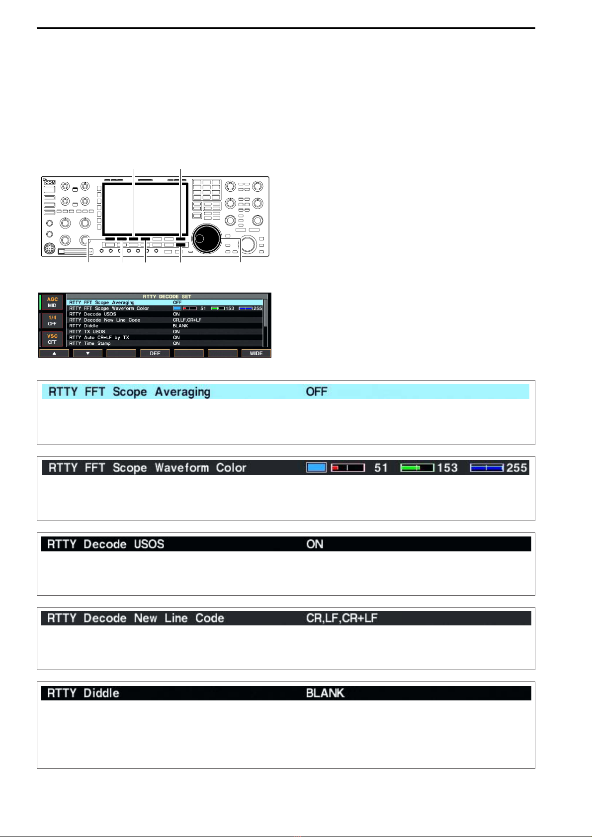
Explicitly inserts the FIGS character even thought it is
not required by the receiving station.
•ON : Inserts FIGS.
•OFF : Does not insert FIGS.
Turn the time stamp (date, transmission or reception
time) indication ON and OFF.
•ON : Displays the time stamp.
•OFF : No time stamp indication.
Selects the clock indication for time stamp usage.
NOTE: The time won’t be displayed when “OFF”is
selected in “RTTY Time Stamp”as above.
•Local : Selects the time that set in “Time (Now).”
•UTC* : Selects the time that set in “CLOCK2.”
*The name of choice may differ according to
“CLOCK2 Name”setting (p, 11-2). “UTC”is the
default name of CLOCK2.
Selects the automatic new line code (CR+LF) trans-
mission capability.
•ON : Transmits CR+LF code once.
•OFF : Transmits no CR+LF code.
Set the text color for transmitted characters.
•The color is set in RGB format.
•The set color is indicated in the box beside the RGB scale.
•Push [F-3•Ω≈] to select R (Red), G (Green) and B (Blue),
and then rotate the main dial to set the ratio from 0 to 255.
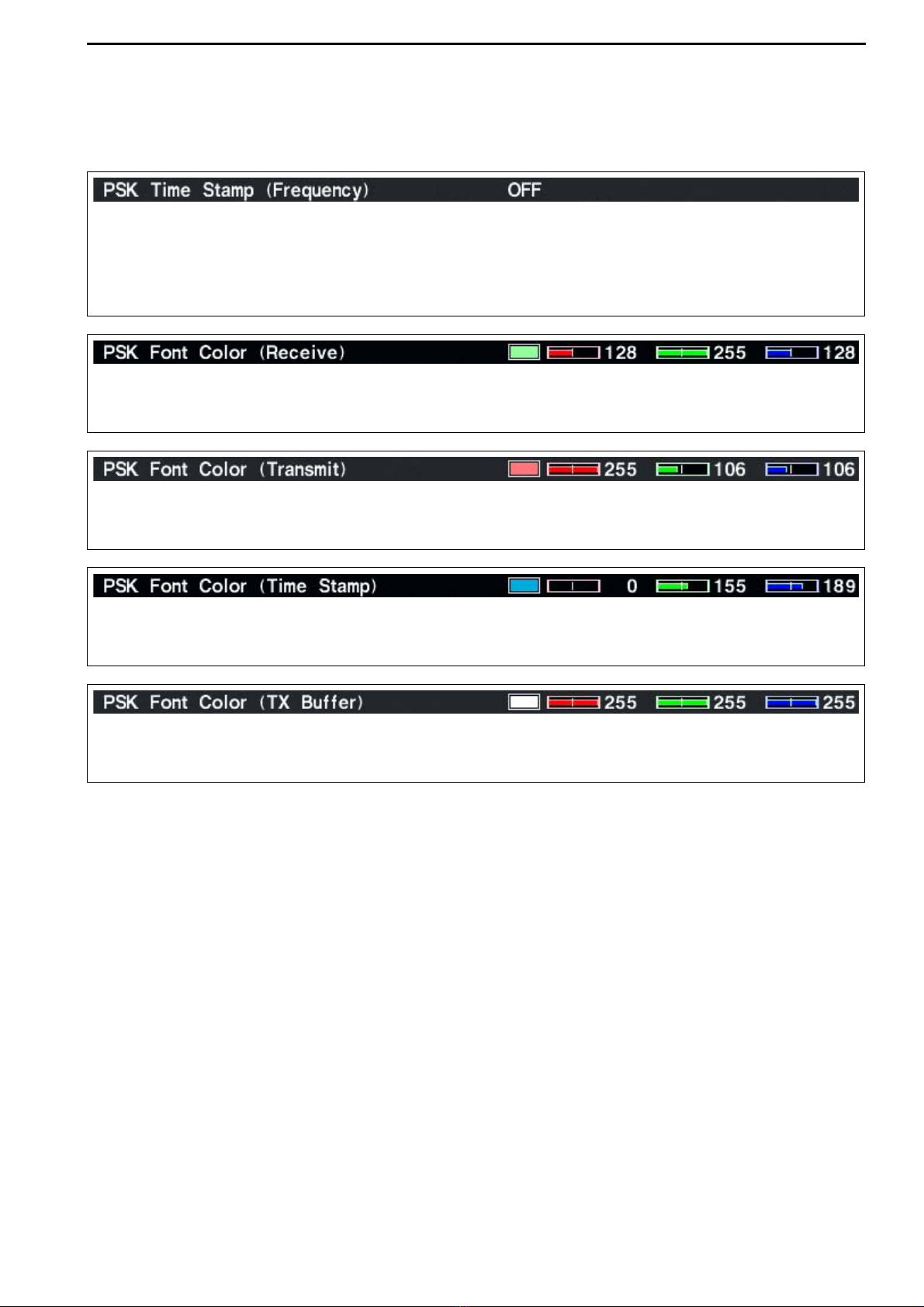
Selects the operating frequency indication for time
stamp usage.
NOTE: The frequency won’t be displayed when “OFF”
is selected in “RTTY Time Stamp”as above.
•ON : Displays the operating frequency.
•OFF : No operating frequency display.
Set the text color for received characters.
•The color is set in RGB format.
•The set color is indicated in the box beside the RGB scale.
•Push [F-3•Ω≈] to select R (Red), G (Green) and B (Blue),
and then rotate the main dial to set the ratio from 0 to 255.
Set the text color for time stamp indication.
•The color is set in RGB format.
•The set color is indicated in the box beside the RGB scale.
•Push [F-3•Ω≈] to select R (Red), G (Green) and B (Blue),
and then rotate the main dial to set the ratio from 0 to 255.
Set the text color in the TX buffer screen.
•The color is set in RGB format.
•The set color is indicated in the box beside the RGB scale.
•Push [F-3•Ω≈] to select R (Red), G (Green) and B (Blue),
and then rotate the main dial to set the ratio from 0 to 255.

4-21
■Operating PSK
A high-quality DSP-based PSK31 encoder/decoder is
built-in to the IC-7800. When connecting a PC key-
board (p. 2-6), PSK31 operation can be performed
without PSK software installed on your PC.
If desired, you can also use your PSK software; con-
sult the manual that comes with the software.
qPush a band key to select the desired band.
wPush [RTTY/PSK] to select PSK.
• After PSK mode is selected, push [RTTY/PSK] for 1 sec.
to toggle between PSK and PSK-R modes.
• “PSK” or “PSK-R” appears.
e
Push [F-3•DECODE] to displays the decoder screen.
• The IC-7800 has a built-in PSK31 decoder.
rTune the desired signal with the main dial.
• The signal is properly tuned when the radiated lines in
the vector tuning indicator narrow, as show in the exam-
ple below.
• The radiated lines in the vector tuning indicator may be
displayed sporadically.
• When a PSK signal is received, the water-fall display is
activated.
• The water-fall display shows the signal condition within
the passband and a vertical line appears when a PSK
signal is received.
tPress [F12] of the connected keyboard to transmit.
• [TX] indicator lights red.
yType from the connected keyboard to enter the
message that you want to transmit.
• The typewritten contents are indicated in the TX buffer
screen and transmitted immediately.
• The text color will be changed when transmitted.
• Press one of [F1]–[F8] to transmit the TX memory con-
tents.
uPress [F12] of the keyboard to return to receive.
✔
For your convenience
The transmission contents can be typed before being
transmitted.
qPerform the steps qto rabove.
wType from the connected keyboard to enter the
message that you want to transmit.
• The message is shown in the TX buffer screen.
ePress [F12] of the connected keyboard to transmit
the message.
• The color of displayed text, in the TX buffer screen, will
be changed when transmitted.
• To cancel the transmission, press [F12] twice.
rPress [F12] of the keyboard to return to receive.
FFT scope
Vector tuning indicator
TX buffer screen
RX contents screen
Water-fall
Appears
[TX] indicator [RX] indicator
[F-3•DECODE] [RTTY/PSK][AF] Main dial
Band keys
4
RECEIVE AND TRANSMIT
• Vector tuning indicator indication example
Tuned BPSK signal
BPSK/QPSK idle signal Unmodulated signal
Tuned QPSK signal

4-23
DDFunctions for the PSK decoder indication
qPush a band key to select the desired band.
wPush [RTTY/PSK] to select PSK.
• After PSK mode is selected, push [RTTY/PSK] for 1 sec.
to toggle between PSK and PSK-R modes.
• “PSK” or “PSK-R” appears.
ePush [F-3•DECODE] to display the decoder screen.
• When tuned into a PSK signal, decoded characters are
displayed in the RX contents screen.
rPush [F-2•HOLD/CLR] to freeze the current screen.
• “ ” appears while the function is in use.
• Push [F-2•HOLD/CLR] again to release the function.
tPush [F-2•HOLD/CLR] for 1 sec. to clear the dis-
played characters.
•“ ” indicator disappears at the same time when the
hold function is in use.
yPush [F-3•AFC/NET] to turn the AFC function ON.
• “ ” appears.
• If a PSK signal is received within the AFC tuning range,
the decoder automatically tunes into the signal and the
offset frequency is displayed.
• The AFC tuning range is set to ±15 Hz as the default.
Optional ±8 Hz setting is available in PSK decode set
mode. (p. 2)
uPush [F-3•AFC/NET] again to turn the NET function
ON.
• “ ” appears additionally.
iPush [F-3•AFC/NET] for 1 sec. to add the offset fre-
quency to the displayed frequency.
oPush [F-7•WIDE] to toggle the PSK decode screen
size from normal and wide.
• S/RF meter type during wide screen indication can be
selected in display set mode. (pgs. 3-11, 12-11)
!0 Push [F-6•MAIN/SUB] to toggle the MAIN and SUB
band for decode operation.
• Dualwatch function (p. 5-16) should be ON when SUB
band is selected for decode operation.
!1 Push [EXIT/SET] to close the PSK decode screen.
DDSetting the decoder threshold level
Adjust the PSK decoder threshold level if some char-
acters are displayed when no signal is received.
qCall up the PSK decoder screen as described
above.
wPush [F-5•ADJ] to select the threshold level setting
condition.
eRotate the main dial to adjust the PSK decoder
threshold level.
• Push [F-6•DEF] for 1 sec. to select the default setting.
rPush [F-5•ADJ] to exit from the threshold level set-
ting condition.
NOTE: The AFC function may not tune the signal
properly when a weak PSK signal is received.
• AFC/NET indications
“AFC”and “NET”indicators Offset frequency
HOLD
HOLD
[F-3•AFC/NET] [F-6•MAIN/SUB] [F-7•WIDE]
[F-2•HOLD/CLR] [RTTY/PSK] [EXIT/SET]
4
RECEIVE AND TRANSMIT

4-26
DDPSK decode set mode
This set mode is used to set the decode USOS func-
tion, time stamp setting, etc.
• Setting contents
qDuring PSK mode operation, push [F-3•DECODE]
to select PSK decode screen.
wPush [F-1•<MENU2>] to select PSK decode menu
2, then push [F-6•SET] to select PSK decode set
mode.
• Push [F-7•WIDE] to toggle the screen size from normal
and wide.
ePush [F-1•Y] or [F-2•Z] to select the desired set
item.
rSet the desired condition using the main dial.
• Push [F-4•DEF] for 1 sec. to select a default condition
or value.
• Push [F-3•Ω≈] to select the set contents for some
items.
tPush [EXIT/SET] to exit from set mode.
[F-1•Y] Main dial[EXIT/SET][F-2•Z][F-4•DEF]
[F-3•Ω ≈] [F-7•WIDE]
4RECEIVE AND TRANSMIT
Turn the time stamp (date, transmission or reception
time) display ON and OFF.
•ON : Displays the time stamp.
•OFF : No time stamp display.
Selects the clock display for time stamp usage.
NOTE: The time won’t be displayed when “OFF”is
selected in “PSK Time Stamp”as above.
•Local : Selects the time that set in “Time (Now).”
•UTC* : Selects the time that set in “CLOCK2.”
*The name of choice may differ according to
“CLOCK2 Name”setting (p, 11-2). “UTC”is the
default name of CLOCK2.
Set the FFT scope waveform averaging function from
2 to 4 and OFF. (default: OFF)
Recommendation!
If you use the FFT scope waveform for tuning, using
the default or smaller number setting is recom-
mended.
Set the color for the FFT scope waveform.
•The color is set in RGB format.
•The set color is indicated in the box beside the RGB scale.
•Push [F-3•Ω≈] to select R (Red), G (Green) and B (Blue),
and then rotate the main dial to set the ratio from 0 to 255.
Select the AFC (Automatic Frequency Control) func-
tion operating range from ±15 Hz (default) and ±8 Hz.
NOTE: The AFC function may not tune the signal
properly when a weak PSK signal is received.

4-27
DDPSK decode set mode (continued)
4
RECEIVE AND TRANSMIT
Selects the operating frequency display for time
stamp usage.
NOTE: The frequency won’t be displayed when
“OFF”is selected in “PSK Time Stamp”as
below left.
•ON : Displays the operating frequency.
•OFF : No operating frequency display.
Set the text color for received characters.
•The color is set in RGB format.
•The set color is indicated in the box beside the RGB scale.
•Push [F-3•Ω≈] to select R (Red), G (Green) and B (Blue),
and then rotate the main dial to set the ratio from 0 to 255.
Set the text color for transmitted characters.
•The color is set in RGB format.
•The set color is indicated in the box beside the RGB scale.
•Push [F-3•Ω≈] to select R (Red), G (Green) and B (Blue),
and then rotate the main dial to set the ratio from 0 to 255.
Set the text color for time stamp indication.
•The color is set in RGB format.
•The set color is indicated in the box beside the RGB scale.
•Push [F-3•Ω≈] to select R (Red), G (Green) and B (Blue),
and then rotate the main dial to set the ratio from 0 to 255.
Set the text color in the TX buffer screen.
•The color is set in RGB format.
•The set color is indicated in the box beside the RGB scale.
•Push [F-3•Ω≈] to select R (Red), G (Green) and B (Blue),
and then rotate the main dial to set the ratio from 0 to 255.

12-3
12
SET MODE
DDScreen arrangement
• Set mode menu screen (p. 12-2)
• Level set mode (p. 12-4)
• ACC set mode (p. 12-6)
• Time set mode (p. 11-2)
• Display set mode (p. 12-11)
• Miscellaneous (Others) set mode (p. 12-14)
• CF card set menu (p. 12-22)

12-5
12
SET MODE
■Level set mode (continued)
Sets the bass level of the receive audio tone in FM
mode from –5 to +5. (default: 0)
Sets the treble level of the receive audio tone in FM
mode from –5 to +5. (default: 0)
Sets the transmission passband width to wide setting
by changing the lower and higher cut-off frequencies.
Lower freq. : 100 (default), 200, 300 and 500 Hz
Higher freq.: 2500, 2700, 2800 and 2900 Hz (default)
Sets the transmission passband width to middle set-
ting by changing the lower and higher cut-off frequen-
cies.
Lower freq. : 100, 200, 300 (default) and 500 Hz
Higher freq.: 2500, 2700 (default), 2800 and 2900 Hz
Sets the transmission passband width to narrow set-
ting by changing the lower and higher cut-off frequen-
cies.
Lower freq. : 100, 200, 300 and 500 Hz (default)
Higher freq.: 2500 (default), 2700, 2800 and 2900 Hz
Sets the voice synthesizer audio output level from 0 to
100% in 1% steps. (default: 50%)
Sets the side tone output level from 0 to 100% in 1%
steps. (default: 50%)
Turns the side tone output level limiting capability from
ON and OFF. (default: ON)
Sets the key-touch beep output level from 0 to 100%
in 1% steps. (default: 50%)
Turns the key-touch beep output level limiting capa-
bility from ON and OFF. (default: ON)

12-11
12
SET MODE
Adjusts the LCD unit brightness from 0 (dark) to 100%
(bright) range in 1% steps. (default: 50%)
Adjusts the switch indicators brightness from 1 (dark)
to 100 (bright) range in 1 steps. (default: 80)
Selects the desired display type from A, B and C.
(default: A)
Selects the desired font for frequency readout from
Italic (1), Italic (2), Italic (3), Italic (4), Round (1),
Round (2), Round (3), Shadow (1), Shadow (2),
Shadow (3), Qubic (1), Qubic (2), Qubic (3), Qubic
(4), IC-780 (1), IC-780 (2), IC-780 (3) and IC-780 (4).
(default: Italic (1))
Selects the desired font for the displays other than fre-
quency readout from Normal and Slim.
(default: Normal)
■Display set mode
Selects the desired S/RF meter type during normal
screen indication from Standard, Edgewise and Bar.
(default: Standard)
Selects the desired S/RF meter type during wide
screen or mini scope indication from Edgewise and
Bar. (default: Edgewise)
Turns the meter peak hold function ON and OFF.
(default: ON)
This function is used for the bar meter only.
Set meter needle response from SLOW, MID and
FAST. (default: MID)
This setting is effective for the standard and edge-
wise meter type selections only.

12-12
12 SET MODE
Selects the pop-up display for the APF filter width
from ON and OFF.
(default: ON)
Turns the pop-up indication capability when the notch
filter width is changed from ON to OFF.
(default: ON)
Select “ON” when the external display is connected.
(default: OFF)
• At least 800×600 pixel resolution is required for the dis-
play.
Selects the suitable pulse level for the connected ex-
ternal display from H and L. (default: H)
Turns the opening message screen indication capa-
bility ON and OFF. (default: ON)
Sets the memory name indication, during memory
mode operation, ON and OFF. (default: ON)
• ON : The programmed memory name is displayed
above the frequency indication.
• OFF : No memory name is displayed even a mem-
ory name is programmed.
■Display set mode (continued)
Turns the screen saver function ON (15, 30 or 60 min-
utes) and OFF. (default: 60 min.)
The screen saver will acts when no operation is per-
formed for the selected time period to protect the LCD
from the “burn-in” effect.
Selects the screen saver type from “Bound,” “Rota-
tion” and “Twist.” (default: Bound)
The screen saver indication can be displayed for your
reference while pushing and holding [F-5•PREVIEW].

13-4
■SWR reading
The SWR meter indicates the SWR over the transmis-
sion line in all modes.
qPush [TUNER] to turn the antenna tuner OFF.
wPush [METER] for 1 sec. to display multi-function
meter.
ePush [RTTY/PSK] once or twice to select RTTY
mode.
rPush [TRANSMIT].
tRotate [RF PWR] clockwise past the 12 o’clock po-
sition for more than 30 W output power.
yRead the SWR on the SWR meter gage.
uPush [EXIT/SET] to close multi-function meter.
The built-in antenna tuner matches the transmitter
to the antenna when the SWR is lower than 3 : 1.
■Screen type and font selections
3 types of screen images and 18 types of frequency
readout indication fonts are available in the IC-7800.
qPush [EXIT/SET] several times to close multi-func-
tion screen, if necessary.
wPush [F-7•SET] to select set mode menu screen.
ePush [F-3•DISP] to enter display set mode.
rPush [F-1•Y] or [F-2•Z] to select “Display Type”
item when selecting the screen image, select “Dis-
play Font” when selecting the frequency readout in-
dication font.
tRotate the main dial to select the desired screen
image or font.
• Screen image is selectable from A, B and C.
• Italic (1)/(2)/(3)/(4), Round (1)/(2)/(3), Shadow (1)/(2)/(3),
Qubic (1)/(2)/(3)/(4) and IC-780 (1)/(2)/(3)/(4) are avail-
able for the frequency readout font.
yPush [EXIT/SET] twice to exit from display set
mode.
S
ID
0
510
15
0
010
44
ALC 52V VD
20
dB
11.5 23
∞
10 50 100 150 200 250
PO
SWR
COMP
A
W
1
59+20 +40 +60dB
Better than 1.5:1
[RF PWR]
[RTTY/PSK][EXIT/SET]
[METER][TRANSMIT]
[TUNER]
13 MAINTENANCE
• Screen image example— type C

14-3
DDCommand table
14
CONTROL COMMAND
Command Sub command Description
00 — Send frequency data
01 Same as Send mode data
command 06
02 — Read band edge frequencies
03 — Read operating frequency
04 — Read operating mode
05 — Set operating frequency
06 00 Select LSB
01 Select USB
02 Select AM
03 Select CW
04 Select RTTY
05 Select FM
07 Select CW-R
08 Select RTTY-R
12 Select PSK
13 Select PSK-R
07 — Select VFO mode
B0 Exchange main and sub bands
B1 Equalize main and sub bands
C0 Turn the dualwatch OFF
C1 Turn the dualwatch ON
D0 Select main band
D1 Select sub band
08 — Select memory mode
0001–0101* Select memory channel
*P1=0100, P2=0101
09 — Memory write
0A — Memory to VFO
0B — Memory clear
0E 00 Scan stop
01 Programmed/memory scan start
02 Programmed scan start
03 ∂F scan start
12 Fine programmed scan start
13 Fine ∂F scan start
22 Memory scan start
23 Select memory scan start
A1–A7 Set ∂F scan span (A1=±5 kHz;
A2=±10 kHz; A3=±20 kHz;
A4=±50 kHz; A5=±100 kHz;
A6=±500 kHz; A7=±1 MHz)
B0 Set as non-select channel
B1 Set as select channel (1=★1;
2=★2; 3=★3; when no data com-
mand is specified, the previously
set number or “★1” is selected)
B2 Set the number for select memory
scan (0=ALL; 1=★1; 2=★2; 3=★3)
D0 Set scan resume OFF
D3 Set scan resume ON
0F 00 Turn the split function OFF
01 Turn the split function ON
10 00 Select 10 Hz (1 Hz) tuning step
01 Select 100 Hz tuning step
02 Select 1 kHz tuning step
03 Select 5 kHz tuning step
04 Select 9 kHz tuning step
05 Select 10 kHz tuning step
06 Select 12.5 kHz tuning step
07 Select 20 kHz tuning step
08 Select 25 kHz tuning step
Command Sub command Description
11 — Select/read attenuator (0=OFF;
1=3 dB; 2=6 dB; 3=9 dB; 4=12 dB;
5=15 dB; 6=18 dB; 7=21 dB)
12 00 + RX ANT Select/read ANT1 selection
(00=RX ANT OFF; 01=RX ANT ON)
01 + RX ANT Select/read ANT2 selection
(00=RX ANT OFF; 01=RX ANT ON)
02 + RX ANT Select/read ANT3 selection
(00=RX ANT OFF; 01=RX ANT ON)
03 + RX ANT Select/read ANT4 selection
(00=RX ANT OFF; 01=RX ANT ON)
13 00 Announce with voice synthesizer
01 (00=all data; 01=frequency and
02 S-meter level; 02=receive mode)
14 01 + Level data [AF] level setting (0=max. CCW to
255=max. CW)
02 + Level data [RF] level setting (0=max. CCW to
255=11 o’clock)
03 + Level data [SQL] level setting (0=11 o’clock to
255=max. CW)
05 + Level data [APF] level setting
(0=Pitch–550 Hz, 128=Pitch,
255=Pitch+550 Hz; 10 Hz steps)
06 + Level data [NR] level setting (0=min. to
255=max.)
07 + Level data Inside [TWIN PBT] setting or IF
shift setting (0=max. CCW,
128=center, 255=max. CW)
08 + Level data Outside [TWIN PBT] setting
(0=max. CCW, 128=center,
255=max. CW)
09 + Level data [CW PITCH] setting (0=300 Hz,
128=600 Hz, 255=900 Hz; 5 Hz
steps)
0A + Level data [RF POWER] setting (0=max.
CCW to 255=max. CW)
0B + Level data [MIC] setting (0=max. CCW to
255=max. CW)
0C + Level data [KEY SPEED] setting (0=max.
CCW to 255=max. CW)
0D + Level data [NOTCH] setting (0=low freq. to
255=high freq.)
0E + Level data [COMP] setting (0=max. CCW to
255=max. CW)
0F + Level data [DELAY] setting (0=max. CCW to
255=max. CW)
11 + Level data [AGC] control setting (0=max.
CCW to 255=max. CW)
12 + Level data [NB] control setting (0=max. CCW
to 255=max. CW)
13 + Level data [DIGI-SEL] setting (0=max. CCW
to 255=max. CW)
14 + Level data [DRIVE] setting (0=max. CCW to
255=max. CW)
15 + Level data [MONI GAIN] setting (0=max.
CCW to 255=max. CW)
16 + Level data [VOX GAIN] setting (0=max.
CCW to 255=max. CW)
17 + Level data [ANTI VOX] setting (0=max. CCW
to 255=max. CW)
18 + Level data [CONTRAST] setting (0=max.
CCW to 255=max. CW)
19 + Level data [BRIGHT] setting (0=max. CCW
to 255=max. CW)

14-7
DDCommand table (continued)
14
CONTROL COMMAND
Command Sub command Description
1A 050134 Send/read voice memory short
play time (3=3 sec. to 10=10 sec.)
050135 Send/read voice memory normal
record time
(5= 5 sec. to 15=15 sec.)
050136 Send/read contest number style
(0=Normal, 1=190→ANO,
2=190→ANT, 3=90→NO,
4=90→NT)
050137 Send/read count up trigger chan-
nel (1=M1, 2=M2, 3=M3, 4=M4)
050138 Send/read present number
(1–9999)
050139 Send/read CW keyer repeat time
(1=1 sec. to 60=60 sec.)
050140 Send/read CW keyer dot/dash
ratio (28=1:1:2.8 to 45=1:1:4.5)
050141 Send/read rise time (0=2 msec.,
1=4 msec., 2=6 msec.,
3=8 msec.)
050142 Send/read paddle polarity
(0=Normal, 1=Reverse)
050143 Send/read keyer type (0=Straight,
1=Bug-key, 2=ELEC-Key)
050144 Send/read mic. up/down keyer set
(0=OFF, 1=ON)
050145 Send/read RTTY decode USOS
(0=OFF, 1=ON)
050146 Send/read RTTY decode new line
code (0=CR,LF,CR+LF,
1=CR+LF)
050147 Send/read RTTY diddle (0=OFF,
1=Blank, 2=Letter)
050148 Send/read RTTY TX USOS
(0=OFF, 1=ON)
050149 Send/read RTTY auto CR+LF by
TX (0=OFF, 1=ON)
050150 Send/read RTTY time stamp set
(0=OFF, 1=ON)
050151 Send/read clock selection for time
stamp (0=Local time, 1=Clock 2)
050152 Send/read frequency stamp
(0=OFF, 1=ON)
050153 Send/read received text font color
(see p. 14-10 for details)
050154 Send/read transmitted text font
color (see p. 14-10 for details)
050155 Send/read time stamp text font
color (see p. 14-10 for details)
050156 Send/read text font color in TX
buffer (see p. 14-10 for details)
050157 Send/read PSK time stamp set
(0=OFF, 1=ON)
050158 Send/read clock selection for time
stamp (0=Local time, 1=Clock 2)
050159 Send/read frequency stamp
(0=OFF, 1=ON)
050160 Send/read received text font color
(see p. 14-10 for details)
050161 Send/read transmitted text font
color (see p. 14-10 for details)
050162 Send/read time stamp text font
color (see p. 14-10 for details)
050163 Send/read text font color in TX
buffer (see p. 14-10 for details)
Command Sub command Description
1A 050164 Send/read scan speed
(0=Low, 1=High)
050165 Send/read scan resume
(0=OFF, 1=ON)
050166 Send/read antenna selection for
0.03 to 1.60 MHz band
(see p. 14-10 for details)
050167 Send/read antenna selection for
1.60 to 2.00 MHz band
(see p. 14-10 for details)
050168 Send/read antenna selection for
2.00 to 6.00 MHz band
(see p. 14-10 for details)
050169 Send/read antenna selection for
6.00 to 8.00 MHz band
(see p. 14-10 for details)
050170 Send/read antenna selection for
8.00 to 11.00 MHz band
(see p. 14-10 for details)
050171 Send/read antenna selection for
11.00 to 15.00 MHz band
(see p. 14-10 for details)
050172 Send/read antenna selection for
15.00 to 20.00 MHz band
(see p. 14-10 for details)
050173 Send/read antenna selection for
20.00 to 22.00 MHz band
(see p. 14-10 for details)
050174 Send/read antenna selection for
22.00 to 26.00 MHz band
(see p. 14-10 for details)
050175 Send/read antenna selection for
26.00 to 30.00 MHz band
(see p. 14-10 for details)
050176 Send/read antenna selection for
30.00 to 45.00 MHz band
(see p. 14-10 for details)
050177 Send/read antenna selection for
45.00 to 60.00 MHz band
(see p. 14-10 for details)
050178 Send/read antenna temporary
memory set (0=OFF, 1=ON)
050179 Send/read antenna selection
(0=OFF, 1=Manual, 2=Auto)
050180 Send/read usage for ANT2
(0=OFF, 1=TX/RX)
050181 Send/read usage for ANT3
(0=OFF, 1=TX/RX)
050182 Send/read usage for ANT4
(0=OFF, 1=TX/RX, 2= RX)
050183 Send/read VOX delay (0=0.0 sec.
to 20=2.0 sec.)
050184 Send/read VOX voice delay
(0=OFF, 1=Short, 2=Long)
050185 Send/read NB depth (0=1 to 9=10)
050186 Send/read NB width
(0=0 to 255=255)
050187 Send/read screen saver set
(0=OFF, 1=15 min., 2=30 min.,
3=60 min.)
050188 Set/read screen saver type
(0=Bound, 1=Rotation, 2=Twist)
050189 Set/read meter response setting
(0=SLOW, 1=MID, 2=FAST)

DDCommand table (continued)
14-8
14 CONTROL COMMAND
Command Sub command Description
1A 050190 Set/read FFT scope averaging set
for RTTY decoder (0=OFF, 1=2,
2=3, 3=4)
050191 Set/read FFT scope waveform
color set for RTTY decoder
(see p. 14-10 for details)
050192 Set/read FFT scope averaging set
for PSK decoder (0=OFF, 1=2,
2=3, 3=4)
050193 Set/read FFT scope waveform
color set for PSK decoder
(see p. 14-10 for details)
050194 Set/read PSK AFC function tuning
range (0=±8 Hz, 1=±15 Hz)
06 Send/read DATA mode with filter
set (see p. 14-10 for detail)
07 Send/read SSB transmit band-
width (0=WIDE, 1=MID, 2=NAR)
08 Send/read DSP filter shape
(0= sharp, 1= soft)
09 Send/read roofing filter set
(0=6 kHz, 1=15 kHz)
0A Send/read manual notch width
(0=Wide, 1=Mid., 2=Nar.)
10 Send/read lock function set
(0=OFF, 1=ON)
1B 00 Set/read repeater tone frequency
(see p. 14-10 for details)
01 Set/read TSQL tone frequency
(see p. 14-10 for details)
1C 00 Set/read the transceiver’s condi-
tion (0=Rx; 1=Tx)
01 Set/read antenna tuner condition
(0=OFF, 1=ON, 2=Start tuning or
while tuning)

14-10
14 CONTROL COMMAND
DDOffset frequency setting
The following data sequence is used when sending or
reading the offset frequency setting.
DDRepeater tone/tone squelch frequency
setting
The following data sequence is used when sending or
reading the tone frequency setting.
DDSSB transmission passband width
setting
The following data sequence is used when sending or
reading the SSB transmission passband width setting.
DDColor setting
The following data sequence is used when sending or
reading the color setting.
DDBandscope edge frequency setting
The following data sequence is used when sending or
reading the bandscope edge frequency setting.
DDData mode with filter width setting
The following data sequence is used when sending or
reading the data mode with filter width setting.
DDAntenna memory setting
The following codes are used when sending or read-
ing the antenna memory setting.
0=ANT1, 1=ANT2, 2=ANT3, 3=ANT4,
4*=TX: ANT1, RX: ANT4, 5*=TX: ANT2, RX: ANT4,
6*=TX: ANT3, RX: ANT4
*RX should be selected for ANT4
q
XXXX
w
00=Data mode OFF
01=FIL1
02=FIL2
03=FIL3
00=Data mode OFF
01=Data mode 1 (D1)
02=Data mode 2 (D2)
03=Data mode 3 (D3)
1 kHz: 0–9
100 Hz: 0 (fixed)
100 kHz: 0–9
10 kHz: 0–9
10 MHz: 0–6
1 MHz: 0–9
1 kHz: 0–9
100 Hz: 0 (fixed)
100 kHz: 0–9
10 kHz: 0–9
10 MHz: 0–6
1 MHz: 0–9
q
XXXXXXXXXXXX
werty
Lower edge Higher edge
1000
100
10
1
q
0XXX0XXX0XXX
werty
1000
100
10
1
1000
100
10
1
R (Red) G (Green) B (Blue)
Using 0000–0255 for each color element.
XX
Higher edge: 0=2500 Hz
1=2700 Hz
2=2800 Hz
3=2900 Hz
Lower edge: 0=100 Hz
1=200 Hz
2=300 Hz
3=500 Hz
100Hz digit: 0–2
10 Hz digit: 0–9
1 Hz digit: 0–9
0.1 Hz digit: 0–9
Fixed digit: 0*
Fixed digit: 0*
q*
00XXX
we
X
*Not necessary when setting a frequency.
1 kHz digit: 0–9
100 Hz digit: 0 (fixed)
100 kHz digit: 0–9
10 kHz digit: 0–9
10 MHz digit: 0–9†
1 MHz digit: 0–4
Direction:
00=+ direction
01=–direction
q
0XXXXXX
we
0
r*
*No need to enter for transverter offset frequency setting.
†Transverter offset only; Fix to ‘0’for split offset setting.
Other manuals for IC-7800
10
Table of contents
Other Icom Transceiver manuals

Icom
Icom IC-M1 euro User manual

Icom
Icom IC-706MKIIG User manual

Icom
Icom IP730D User manual

Icom
Icom IC-F3061T User manual

Icom
Icom IC-2350H User manual

Icom
Icom IC-H19s3 User manual

Icom
Icom IC-F1000S User manual

Icom
Icom IC-2330A User manual

Icom
Icom IC-78 Assembly instructions

Icom
Icom IC-2340H User manual