Icom IC-M412 User manual

INSTRUCTION MANUAL
New2001
iM412
VHF MARINE TRANSCEIVER

i
New2001
FOREWORD
Thank you for purchasing this Icom product. The IC-M412
vhf marine transceiver is designed and built with Icom’s
state of the art technology and craftsmanship. With proper
care, this transceiver should provide you with years of trou-
ble-free operation.
We appreciate you making the IC-M412 your radio of choice,
and hope you agree with Icom’s philosophy of “technology first.”
Many hours of research and development went into the de-
sign of your IC-M412.
DFEATURES
mAdvanced receiver performance
mEasy to hear speaker
mBuilt-in DSC meets Class D requirement
mRugged waterproof construction
mFavorite channel function
mAquaQuake water draining function
IMPORTANT
READ ALL INSTRUCTIONS carefully and completely
before using the transceiver.
SAVE THIS INSTRUCTION MANUAL — This in-
struction manual contains important operating instructions
for the IC-M412.
EXPLICIT DEFINITIONS
WORD DEFINITION
RWARNING!
CAUTION
NOTE
Personal injury, fire hazard or electric
shock may occur.
Equipment damage may occur.
Recommended for optimum use. No risk of
personal injury, fire or electric shock.
CLEAN THE TRANSCEIVER AND MICROPHONE
THOROUGHLY WITH FRESH WATER after exposure
to water including salt water, otherwise, the keys and
switches may become inoperable due to salt crystalliza-
tion.
Icom, Icom Inc. and the Icom logo are registered trademarks of Icom Incor-
porated (Japan) in Japan, the United States, the United Kingdom, Germany,
France, Spain, Russia and/or other countries.

ii
New2001
IN CASE OF EMERGENCY
If your vessel requires assistance, contact other vessels and
the Coast Guard by sending a Distress call on Channel 16.
USING CHANNEL 16
DISTRESS CALL PROCEDURE
1. “MAYDAY MAYDAY MAYDAY.”
2. “THIS IS ...............” (name of vessel)
3. Your call sign or other indication of the vessel (AND
9-digit DSC ID if you have one).
4. “LOCATED AT ...............” (your position)
5. The nature of the distress and assistance required.
6. Any other information which might facilitate the rescue.
Or, transmit your Distress call using digital selective calling
on Channel 70.
USING DIGITAL SELECTIVE CALLING (Ch 70)
DISTRESS CALL PROCEDURE
1. While lifting up the key cover, hold down [DISTRESS]
for 5 seconds until you hear 5 short beeps change to
one long beep.
2. Wait for an acknowledgment on Channel 70 from a
coast station.
•Aftertheacknowledgementisreceived,Channel16is
automatically selected.
3. Hold down [PTT], then transmit the appropriate
information as listed above.
NOTE
A WARNING STICKER is supplied with the transceiver.
To comply with FCC regulations, this sticker must be affixed in
such a location as to be readily seen from the operating
controls of the radio as in the diagram below. Make sure the
chosen location is clean and dry before applying the sticker.
(p. 36)
EXAMPLE
WARNING
STICKER

iii
New2001
RADIO OPERATOR WARNING
WARNING
Icom requires the radio operator to meet the
FCC Requirements for Radio Frequency
Exposure. An omnidirectional antenna with
gain not greater than 9 dBi must be mounted a
minimum of 5 meters (measured from the
lowest point of the antenna) vertically above
the main deck and all possible personnel. This is the
minimum safe separation distance estimated to meet all RF
exposure compliance requirements. This 5 meter distance is
based on the FCC Safe Maximum Permissible Exposure
(MPE) distance of 3 meters added to the height of an adult
(2 meters) and is appropriate for all vessels.
For watercraft without suitable structures, the antenna
must be mounted so as to maintain a minimum of 1 meter
vertically between the antenna, (measured from the lowest
point of the antenna), to the heads of all persons AND all
persons must stay outside of the 3 meter MPE radius.
Do not transmit with radio and antenna when persons are
within the MPE radius of the antenna, unless such persons
(such as driver or radio operator) are shielded from antenna
field by a grounded metallic barrier. The MPE Radius is the
minimum distance from the antenna axis that person should
maintain in order to avoid RF exposure higher than the
allowable MPE level set by FCC.
FAILURE TO OBSERVE THESE LIMITS MAY ALLOW
THOSE WITHIN THE MPE RADIUS TO EXPERIENCE RF
RADIATION ABSORPTION WHICH EXCEEDS THE FCC
MAXIMUM PERMISSIBLE EXPOSURE (MPE) LIMIT.
IT IS THE RESPONSIBILITY OF THE RADIO OPERATOR
TO ENSURE THAT THE MAXIMUM PERMISSIBLE
EXPOSURE LIMITS ARE OBSERVED AT ALL TIMES
DURING RADIO TRANSMISSION. THE RADIO
OPERATOR IS TO ENSURE THAT NO BYSTANDERS
COME WITHIN THE RADIUS OF THE MAXIMUM
PERMISSIBLE EXPOSURE LIMITS.
Determining MPE Radius
THE MAXIMUM PERMISSIBLE EXPOSURE (MPE)
RADIUS HAS BEEN ESTIMATED TO BE A RADIUS OF
ABOUT 3M PER OET BULLETIN 65 OF THE FCC.
THIS ESTIMATE IS MADE ASSUMING THE MAXIMUM
POWER OF THE RADIO AND ANTENNAS WITH A
MAXIMUM GAIN OF 9dBi ARE USED FOR A SHIP
MOUNTED SYSTEM.

iv
New2001
TABLE OF CONTENTS
FOREWORD ..................................................................................... i
IMPORTANT...................................................................................... i
EXPLICIT DEFINITIONS................................................................... i
IN CASE OF EMERGENCY............................................................. ii
NOTE................................................................................................ ii
RADIO OPERATOR WARNING ...................................................... iii
TABLE OF CONTENTS................................................................... iv
PRECAUTIONS................................................................................ v
1 OPERATING RULES ..................................................................1
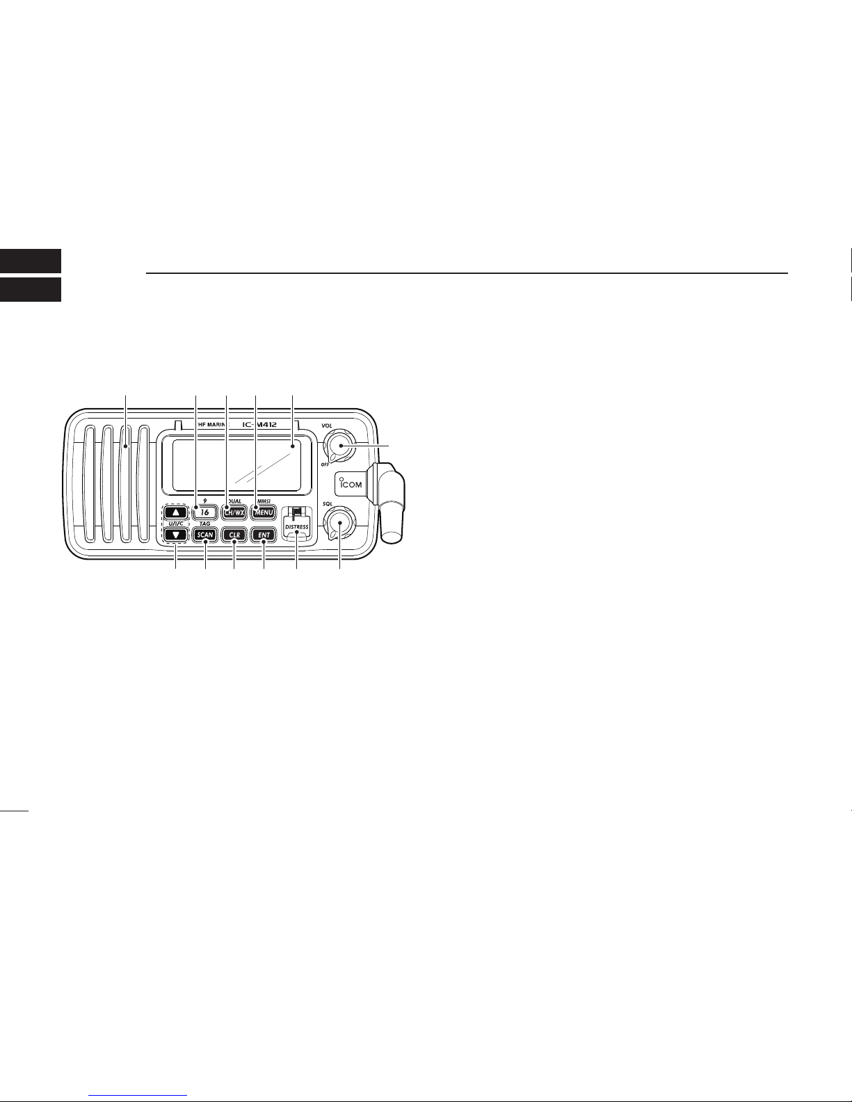
2 PANEL DESCRIPTION ...........................................................2–4
n Front panel...............................................................................2
n Microphone..............................................................................3
n Function display.......................................................................4
3 BASIC OPERATION ...............................................................5–9
n Channel selection ....................................................................5
n Receiving and transmitting ......................................................7
n Call channel programming.......................................................8
n Channel comments..................................................................8
n Microphone Lock function........................................................9
n Display backlight......................................................................9
n AquaQuake water draining function.........................................9
4 SCAN OPERATION ............................................................10–11
n Scan types.............................................................................10
n Setting TAG channels ............................................................11
n Starting a scan.......................................................................11
5 DUALWATCH/TRI-WATCH ....................................................... 12
n Description.............................................................................12
n Operation...............................................................................12
6 DSC OPERATION...............................................................13–40
n MMSI code programming ......................................................13
n DSC address ID.....................................................................14
n Position and time programming .............................................17
n Position indication..................................................................18
n Distress call ...........................................................................18
n Transmitting DSC calls...........................................................21
n Receiving DSC calls ..............................................................34
n Received messages ..............................................................38
n Automatic acknowledgement ................................................40
n Offset time .............................................................................40
7 SET MODE..........................................................................41–43
n Set mode programming .........................................................41
n Set mode items......................................................................42
8 CONNECTIONS AND MAINTENANCE..............................44–47
n Connections...........................................................................44
n Antenna .................................................................................45
n Fuse replacement..................................................................45
n Cleaning.................................................................................45
n Supplied accessories.............................................................45
n Mounting the transceiver .......................................................46
n Optional MB-69 installation....................................................47
9 TROUBLESHOOTING ..............................................................48
10 SPECIFICATIONS AND OPTION ....................................... 49–51
n Specifications.........................................................................49
n Option ....................................................................................51
11 CHANNEL LIST ..................................................................52–53
12 TEMPLATE ...............................................................................55

v
New2001
RWARNING! NEVER connect the transceiver to an
AC outlet. This may pose a fire hazard or result in an electric
shock.
CAUTION: Changes or modifications to this device, not
expressly approved by Icom Inc., could void your authority to
operate this device under FCC regulations.
RWARNING! NEVER connect the transceiver to a
power source of more than 16 V DC or use reverse polarity.
This will ruin the transceiver.
RWARNING! NEVER cut the DC power cable between
the DC plug at the back of the transceiver and fuse holder. If
an incorrect connection is made after cutting, the transceiver
may be damaged.
CAUTION: NEVER place the transceiver where normal
operation of the vessel may be hindered or where it could
cause bodily injury.
CAUTION: KEEP the transceiver at least 3.3 ft (1 m)
away from the ship’s navigation compass.
DO NOT use or place the transceiver in areas with tem-
peratures below –4°F (–20°C) or above +140°F (+60°C), or
in areas subject to direct sunlight, such as the dashboard.
DO NOT use harsh solvents such as benzine or alcohol to
clean the transceiver, as they will damage the transceiver’s
surfaces. If the transceiver becomes dusty or dirty, wipe it
clean with a soft, dry cloth.
BE CAREFUL! The transceiver rear panel will become
hot when operating continuously for long periods of time.
Place the transceiver in a secure place to avoid inadvertent
use by children
BE CAREFUL! The transceiver employs waterproof
construction, which corresponds to IPX7 of the international
standard IEC 60529 (2001). However, once the transceiver
has been dropped, waterproofing cannot be guaranteed due
to the fact that the case may be cracked, or the waterproof
seal damaged, etc.
Approved Icom optional equipment is designed for optimal
performance when used with an Icom transceiver.
Icom is not responsible for the destruction or damage to an
Icom transceiver in the event the Icom transceiver is used
with equipment that is not manufactured or approved by
Icom.
PRECAUTIONS

1
1
OPERATING RULES
DPRIORITIES
•Readallrulesandregulationspertainingtoprioritiesand
keep an up-to-date copy handy. Safety and Distress calls
take priority over all others.
•YoumustmonitorChannel16whenyouarenotoperating
on another channel.
•Falseorfraudulentdistresssignalsareprohibitedandpun-
ishable by law.
DPRIVACY
•Informationoverheardbutnotintendedforyoucannotlaw-
fully be used in any way.
•Indecentorprofanelanguageisprohibited.
DRADIO LICENSES
(1) SHIP STATION LICENSE
You must have a current radio station license before using
the transceiver. It is unlawful to operate a ship station which
is not licensed.
Inquire through your dealer or the appropriate government
agency for a Ship-Radiotelephone license application. This
government-issued license states the call sign which is your
craft’s identification for radio purposes.
(2) OPERATOR’S LICENSE
A Restricted Radiotelephone Operator Permit is the license
most often held by small vessel radio operators when a radio
is not required for safety purposes.
The Restricted Radiotelephone Operator Permit must be
posted or kept with the operator. Only a licensed radio op-
erator may operate a transceiver.
However, non-licensed individuals may talk over a trans-
ceiver if a licensed operator starts, supervises, ends the call
and makes the necessary log entries.
Keep a copy of the current government rules and regulations
handy.
1
Radio license for boaters (U.S.A. only)
The Telecommunications Act of 1996 permits recreational
boaters to have and use a VHF marine radio, EPIRB, and
marine radar without having an FCC ship station license.
Boaters traveling on international voyages, having an
HF single sideband radiotelephone or marine satellite
terminal, or required to carry a marine radio under any
other regulation must still carry an FCC ship station
license. For further information, see the FCC Ship Radio
Stations Fact Sheet.

2
New2001
PANEL DESCRIPTION
2
nFront panel
Function display (p. 4)Speaker i!0o
weuytr
q
qPOWER•VOLUMECONTROL[VOL]
➥Rotate to turn the transceiver power ON or OFF.
➥Rotate to adjust the audio level.
wSQUELCH CONTROL [SQL] (p. 7)
Rotate to set the squelch threshold level.
eDISTRESS KEY [DISTRESS] (p. 18)
Hold down for 5 seconds to transmit a Distress call.
rENTER KEY [ENT]
Push to set the DSC menu, a channel comment, etc.
tCLEAR KEY [CLR]
Push to cancel the entered function, or exits the Set
mode.
ySCAN•TAGCHANNELKEY
[SCAN]•[TAG](SCAN) (p. 11)
➥Push to start and stop the Normal or Priority scan.
➥Hold down for 1 second to set or clear the displayed
channel as a tag (scanned) channel.
➥While holding down [HI/LO] on the microphone, hold
down this key for 3 seconds to set or clear all tag chan-
nels in the selected channel group.
uCHANNELUP/DOWN•CHANNELGROUPKEYS
[s]/[t]•[U/I/C]
➥Push to select the operating channels, Set mode set-
tings, DSC menu items, etc. (pp. 5, 6, 13, 41)
➥Hold down [Y]to continuously move upward through
the operating channels.
➥Hold down [Z]to continuously move downward
through the operating channels
➥Push both keys to select one of three channel groups
in sequence. (p. 6)
•USA,InternationalandCanadianchannelsareselectable.
➥While holding down [SCAN], push [Y]or [Z]to adjust
the brightness of the LCD and key backlight. (p. 9)
➥While holding down both keys, turn ON the power to
activates the AquaQuake function. (p. 9)
➥During scan operation, Checks TAG channels, changes
scanning direction or resumes the scan manually. (p. 11)

3
2
PANEL DESCRIPTION
New2001
iCHANNEL16/CALLCHANNELKEY[16]•[9](16)
➥Push to select Channel 16. (p. 5)
➥Hold down for 1 second to select Call channel. (p. 5)
•“CALL” appears when Call channel is selected.
➥When the Call channel is selected, hold down for 3 sec-
onds to enter the Call channel programming mode. (p. 8)
➥While holding down [CH/WX], push to enter the chan-
nel comment programming mode. (p. 8)
➥While in the channel comment programming mode,
push to move the cursor backward. (p. 9)
➥
While holding down this key, turn ON the power to enter
the Set mode. (p. 41)
oCHANNEL/WEATHER CHANNEL KEY /DUALWATCH/
TRI-WATCHKEY[CH/WX]•[DUAL](CH/WX)
➥Selects and toggles the regular channel and Weather
channel when pushed momentarily. (pp. 5, 6)
➥Hold down for 1 second to start Dualwatch or Tri-watch.
(p. 12)
•PushtostopDualwatchorTri-watchwheneitherisactivated.
➥While in the channel comment programming mode,
push to advance the cursor. (p. 9)
!0DSCMENUKEY[MENU]•[MMSI](MENU) (p. 13)
➥Push to turn the DSC menu ON or OFF.
➥Hold down for 1 second to display the MMSI code on
the channel comment indicator. (pp. 5, 6)
nMicrophone
Microphone
q
e
w
qPTT SWITCH [PTT]
Hold down to transmit; release to receive. (p. 7)
wCHANNEL UP/DOWN KEYS [Y]/[Z]
➥Push to select the operating channels, Set mode set-
tings, DSC menu items, etc. (pp. 5, 6, 13, 41)
➥During scan operation, checks TAG channels, changes
scanning direction or manually resumes the scan.
(p. 11)
eTRANSMIT POWER KEY [HI/LO]
➥Push to select the output power high or low. (p. 7)
•Somechannelsaresettolowpoweronly.
➥
While holding down this key, turn ON the power to tog-
gle the Microphone Lock function ON or OFF. (p. 9)
2

4
2PANEL DESCRIPTION
New2001
nFunction display
yio u
!2
!3
!1
!0
w
e
r
t
q
qCHANNEL COMMENT INDICATOR
➥Channel comment appears and scrolls for about 10 sec-
onds after the channel selection, if programmed. (p. 8)
➥“ SCAN 16” appears during Priority scan; “SCAN” ap-
pears during Normal scan. (p. 11)
➥“DW 16” appears during Dualwatch; “TW 16” appears
during Tri-watch. (p. 12)
➥In the Set mode, displays and scrolls the selected item. (p. 41)
wWEATHER CHANNEL ICONS (pgs. 6, 33)
➥“ WX” appears when a weather channel is selected.
➥“ WX ALT” appears when the Weather Alert function is
in use; blinks when an alert tone is received.
eTAG CHANNEL ICON (p. 11)
Appears when a TAG channel is selected.
rDUPLEX ICON (p. 6)
Appears when a duplex channel is selected.
tLOW BATTERY ICON
Appears when the battery voltage drops to approximately
10 V DC or below.
yDSC ICONS
Indicates the DSC status.
•“DSC” appears when a DSC call is received. (pp. 23, 34)
•“POS REPLY” appears when a Position Reply call is received.
(p. 37)
uGPS INDICATOR
➥Appears while valid position data is received.
➥Blinks when invalid position data is received.
➥Disappears when no GPS receiver is connected.
iCHANNEL NUMBER READOUT
➥Indicates the selected operating channel number.
•“A” appears when a simplex channel is selected.
➥In the Set mode, displays the selected option. (p. 41)
oLOW POWER ICON (p. 7)
Appears when low power is selected.
!0 CHANNEL GROUP ICON (p. 6)
Displays whether a U.S.A. “USA,” International “INT” or
Canadian “CAN” channel group is selected.
!1 CALL CHANNEL ICON (p. 5)
Appears when the Call channel is selected.
!2 BUSY ICON (p. 7)
Appears when receiving a signal or when the squelch
opens.
!3 TRANSMIT ICON (p. 7)
Appears while transmitting.

5
3
BASIC OPERATION
2
3
nChannel selection
ïChannel 16
Channel 16 is the distress and safety channel. It is used for
establishing initial contact with a station and for emergency
communications. Channel 16 is monitored during both Du-
alwatch and Tri-watch. While standing by, you must monitor
Channel 16.
➥Push [16] momentarily to select Channel 16.
➥Push [CH/WX] to return to the display before selecting
Channel 16, or push [Y]or [Z]to select an operating
channel.
Push
Convenient!
When the Favorite channel function is turned ON (p. 43),
[Y]/[Z] keys on the microphone select the favorite channels
in the selected channel group in sequence when pushed.
•ThefavoritechannelsaresetbytheTAGchannelsetting.(p.11)
ïChannel 9 (Call channel)
Each regular channel group has a separate leisure-use Call
channel. The Call channel is monitored during Tri-watch. The
Call channels can be programmed (p. 8) and are used to
store your most often used channel in each channel group
for quick recall.
➥Hold down [9](16) for 1 second to select the Call channel
of the selected channel group.
•“CALL” and Call channel number appear.
•EachchannelgroupmayhaveanindependentCallchannel
after programming a Call channel. (p. 8)
➥Push [CH/WX] to return to the display before selecting
Call channel, or push [Y]or [Z]to select an operating
channel.
Hold down
for 1 sec.

6
3BASIC OPERATION
New2001
ïU.S.A., international and Canadian
channels
The IC-M412 is pre-programmed with 57 USA, 57 interna-
tional and 61 Canadian channels. These channel groups
may be specified for the operating area.
qPush [CH/WX] to select a regular channel.
•Ifaweatherchannelappears,push[CH/WX] again.
e Push [U/I/C] (both [Y]and [Z]) to change the channel
group. (p. 6)
•USA,InternationalandCanadianchannelgroupscanbese-
lected in sequence.
both ()and
Push
ePush [Y]or [Z]to select a channel.
•“DUP” appears for duplex channels.
•“ ” appears when a simplex channel is selected.
ïWeather channels
The IC-M422 has 10 weather channels. These are used for
monitoring broadcasts from NOAA (National Oceanic and
Atmospheric Administration.)
The transceiver can detect a weather alert tone on the se-
lected weather channel while receiving the channel, during
standby on a regular channel or while scanning. (p. 33)
qPush [CH/WX] once or twice to select a weather chan-
nel.
•“WX” appears when a weather channel is selected.
•“WX ALT” appears when the Weather Alert function is in use.
(p. 33)
Scrolls
Appears
Scrolls
Appears
When Weather alert is OFF.
When Weather alert is ON.
Push once or twice
wPush [Y]or [Z]to select a channel.

7
3
BASIC OPERATION
New2001
3
nReceiving and transmitting
CAUTION: Transmitting without an antenna may dam-
age the transceiver.
qRotate [VOL] to turn ON the power.
wSet the audio and squelch levels.
➥Rotate [SQL] fully counterclockwise.
➥Rotate [VOL] to adjust the audio output level.
➥Rotate [SQL] clockwise until the noise disappears.
While in the DSC operation, please make sure you set
the squelch correctly.
e Push [U/I/C] (both [Y]and [Z]) to change the channel
group. (p. 6)
rPush [Y]or [Z]to select a desired channel. (pp. 5, 6, 52)
•Whenreceivingasignal,“ ” appears and audio is emitted
from the speaker.
•Furtheradjustmentof[VOL] may be necessary.
t Push [HI/LO] on the microphone to select the output
power if necessary.
•“LOW” appears when low power is selected.
•Chooselowpowerforshortrangecommunications,choose
high power for longer distance communications.
•Somechannelsareforlowpoweronly.
y Hold down [PTT] to transmit, then speak into the micro-
phone (*).
•“ ” appears.
•Channel70cannotbeusedfortransmissionotherthanDSC.
u Release [PTT] to receive.
IMPORTANT: To maximize the readability of your trans-
mitted signal, pause a few seconds after holding down
[PTT], hold the microphone 5 to 10 cm from your mouth
and speak into the microphone (*) at a normal voice
level.
u
w
re
M
qy
rt
M: Microphone
4NOTE for TOT (Time-out Timer) function
The TOT function inhibits continuous transmission over a
preset time period after the transmission starts.
A beep sounds 10 seconds before the TOT function acti-
vates, to indicate the transmission will be shut down and
“TOT” appears on the channel comment indicator. Transmis-
sion is not possible for 10 seconds after this transmission
shut down.

8
3BASIC OPERATION
New2001
nCall channel programming
Call channel is used to select Channel 9 (default), however,
you can program the Call channel with your most often-used
channels in each channel group for quick recall.
qPush both [Y]and [Z]on the transceiver one or more
times to select a desired channel group (U.S.A., Interna-
tional or Canada) to be programmed.
wHold down [9](16) for 1 second to select the Call channel
of the selected channel group.
•“CALL” and Call channel num-
ber appear.
eHold down [9](16) again for
3 seconds (until a long beep
changes to two short beeps)
to enter the Call channel
programming mode.
•Channelnumberstartsblink-
ing.
r Push [Y]or [Z]to select a
desired channel.
t Push [9](16) to program the
displayed channel as the
Call channel.
•Push[CLR] to cancel.
•Thechannelnumberstops
blinking.
nChannel comments
The channels can be labeled with a unique alphanumeric ID
of up to 10 characters.
Comment is indicated at the channel comment indicator for
about 10 seconds after the channel selection, and the com-
ment, more than 7 characters long, automatically scrolls.
Capital letters, small letters (except f, j, k, p, s, v, x, z), 0 to 9,
some symbols (= M+ – . /) and space can be used.
q Select a desired channel.
•CancelDualwatch,Tri-watchorScaninadvance.
w While holding down [CH/
WX], push [16] to edit the
channel comment program-
ming mode.
•Acursorandthefirstcharac-
ter start blinking alternately.
e Push [Y]or [Z]to select a desired character.
•Push[CH/WX] or [16] to move the cursor forward or backward.
r Repeat step eto input all characters.
t Push [ENT] to input and set the comment.
•Push[CLR] to cancel and exit the programming mode.
•Thecursorandthecharacterstopblinking.
y If desired, repeat steps qto tto program other channel
comments.

9
3
BASIC OPERATION
New2001
3
nMicrophone Lock function
The Microphone Lock function electrically locks the [Y]and
[Z]keys on the supplied microphone. This prevents acci-
dental channel changes and function access.
➥While holding down [HI/LO] on the microphone, turn ON
the power to toggle the Microphone Lock function ON or
OFF.
[HI/LO]
[Y]/[Z]
nDisplay backlight
The function display and keys can be backlit for better visibil-
ity under low light conditions.
Display backlight is also adjustable via the Set mode. (p. 43)
➥While holding down [SCAN], push [Y]or [Z]to adjust
the brightness of the LCD and key backlight.
•Thebacklightisadjustablein4levelsandOFF.
nAquaQuake water draining
function
The IC-M412 uses a technology to clear water away from
the speaker grill: AquaQuake. AquaQuake helps drain water
away from the speaker housing (water that might otherwise
muffle the sound coming from the speaker). The IC-M412
emits a vibrating noise when this function is being used.
➥While holding down both [Y]and [Z]on the transceiver,
turn ON the power to activate the AquaQuake function.
•Whilecontinuingtopush[Y]and [Z], a low beep tone sounds
to drain water, regardless of the [VOL] control setting.
•WhiletheAquaQuakefunctionisactivated,thetransceiver
never accepts any key operations.
•Release[Y]and [Z]to cancel the AquaQuake function.

10
New2001
SCAN OPERATION
4
nScan types
Scanning is an efficient way to locate signals quickly over a
wide frequency range. The transceiver has Priority scan and
Normal scan.
When the Weather Alert function is turned ON, the previ-
ously selected (last used) weather channel is also checked
while scanning. (p. 33)
Set the TAG channels (scanned channel) before scanning.
Clear the TAG channels which inconveniently stop scanning,
such as those for digital communication use. (Refer to right
page for details.)
Choose Priority or Normal scan in the Set mode. (p. 42)
PRIORITY SCAN
CH 06
CH 01
CH 16
CH 02
CH 05 CH 04
CH 03
Priority scan searches through all TAG channels in se-
quence while monitoring Channel 16. When a signal is
detected on Channel 16, scan pauses until the signal
disappears; when a signal is detected on a channel other
than Channel 16, scan becomes Dualwatch until the sig-
nal disappears.
NORMAL SCAN
CH 01 CH 02
CH 06
CH 05 CH 04
CH 03
Normal scan, like Priority scan, searches through all TAG
channels in sequence. However, unlike Priority scan,
Channel 16 is not checked unless Channel 16 is set as a
TAG channel.

11
4
SCAN OPERATION
New2001
4
nSetting TAG channels
For more efficient scanning, add a desired channels as TAG
channels or clear the TAG for unwanted channels.
Channels that are not tagged will be skipped during scan-
ning. TAG channels can be independently assigned to each
channel group (USA, INT, CAN).
q Push [U/I/C] (both [Y]and [Z]) to select a desired chan-
nel group.
wSelect a desired channel to be set as a TAG channel.
eHold down [TAG](SCAN) for 1 second to set the dis-
played channel as a TAG channel.
•“ ” appears in the display.
r To cancel the TAG channel setting, repeat step e.
•“ ” disappears.
✓Clearing (or setting) all tagged channels
While holding down [HI/LO] on the microphone, hold down
[TAG](SCAN) for 3 seconds (until a long beep changes to two
short beeps) to clear all TAG channels in the channel group.
•RepeataboveproceduretosetallTAGchannels.
nStarting a scan
Set scan type (Priority or Normal scan) and scan resume
timer in advance, using the Set mode. (p. 42)
q Push [U/I/C] (both [Y]and [Z]) to select a desired chan-
nel group.
w Set TAG channels as described at left.
e Make sure the squelch is closed to start a scan.
r Push [SCAN] to start Priority or Normal scan.
•“SCAN”blinksatthechannelcommentindicatorduringscan-
ning. (During Priority scan, “16” appears beside the blinking
“SCAN” indication.)
•Abeeptonesoundsand“16”blinksatthechannelcommentin-
dicator when a signal is received on Channel 16 during Priority
scan.
•Whenasignalisdetected,scanpausesuntilthesignaldisap-
pears or resumes after pausing 5 seconds, depending on the
Set mode setting. (Channel 16 is still monitored during Priority
scan.)
•Push[Y]or [Z]to check the scanning TAG channels, to
change the scanning direction or resume the scan manually.
t To stop the scan, push [SCAN] again.
[Example]: Starting a Normal scan.
Push Scan starts.
When a signal is
received.
BlinksBlinks
Appears

12
New2001
DUALWATCH/TRI-WATCH
5
nDescription
Dualwatch monitors Channel 16 while you are receiving on
another channel; Tri-watch monitors Channel 16 and the
Call channel while receiving another channel. Dualwatch/Tri-
watch is convenient for monitoring Channel 16 when you are
operating on another channel.
nOperation
q Select Dualwatch or Tri-watch in the Set mode. (p. 42)
w Push [Y]or [Z]to select a desired channel.
e Hold down [DUAL](CH/WX) for 1 second to start Dual-
watch or Tri-watch.
•“DW”blinksduringDualwatch;“TW”blinksduringTri-watch.
•Abeeptonesoundsand“16”blinkswhenasignalisreceived
on Channel 16.
r To cancel Dualwatch/Tri-watch, push [DUAL](CH/WX) again.
DUALWATCH/TRI-WATCH SIMULATION
DualwatchTri-watch
Call channel
•IfasignalisreceivedonChannel16,Dualwatch/Tri-
watch pauses on Channel 16 until the signal disappears.
•IfasignalisreceivedontheCallchannelduringTri-
watch, Tri-watch becomes Dualwatch until the signal dis-
appears.
•TotransmitontheselectedchannelduringDualwatch/
Tri-watch, hold down [PTT].
[Example]: Operating Tri-watch on INT Channel 25
Tri-watch starts.
Signal is received on Call
channel.
Signal is received on
Channel 16 takes priority.
Tri-watch resumes after
the signal disappears.

13
6
DSC OPERATION
5
6
nMMSI code programming
The 9-digit MMSI (Maritime Mobile Service Identity: DSC
self ID) code can be programmed at power ON.
This function is not available when the MMSI code has
been programmed by the dealer. This code programming
can be performed only twice.
q Turn OFF the power.
w While holding down [MMSI](MENU), turn ON the power
to enter MMSI code programming mode.
eAfter the display appears, release [MMSI](MENU).
r Push [MENU] to enter the DSC menu.
t Push [Y]or [Z]to select “MMSI” and push [ENT].
•Acursorstartsblinking.
y Push [Y]or [Z]to select the specified MMSI code.
•Push[CH/WX] or [16] to move the cursor forward or backward.
u After programming the 9-digit MMSI code, push [ENT].
•“CONFIRMATION”scrollsatthechannelcommentindicator.
Scrolls
i Push [ENT], then input the same MMSI code as step y
for the confirmation.
o Push [ENT] to set the code.
•Returnstothenormaloperation.
•Push[CLR] to cancel and exit the programming mode.
•Ifthedifferentcodeisinput,“INCORRECT” appears. Push
[ENT] and try steps yto iagain.
DMMSI code check
The 9-digit MMSI (DSC self ID) code can be checked.
➥Hold down [MMSI](MENU) for 1 second to display the
9-digit MMSI (DSC self ID) code.
•TheMMSIcodeisdisplayedandscrollsatthechannelcom-
ment indicator.
•WhennoMMSIcodeisprogrammed,“NOMMSI”appearsand
warning alarm sounds.
Scrolls

14
6DSC OPERATION
New2001
nDSC address ID
A total of 100 DSC address IDs (9-digit) can be programmed
and named with up to 10 characters.
DProgramming Address ID
q Push [MENU] to enter the DSC menu.
w Push [Y]or [Z]to select “ADDRESS,” push [ENT].
e Push [Y]or [Z]to select “ADD INDV ID,” push [ENT].
Scrolls
r Push [Y]or [Z]to set the 9-digit Individual ID, push
[ENT].
•Push[CH/WX] or [16] to move the cursor forward or backward.
•Push[CLR] to cancel and exit the programming mode.
t Push [Y]or [Z]to set up to a 10-character ID name.
•Push[CH/WX] or [16] to move the cursor forward or backward.
•Push[CLR] to cancel and exit the programming mode.
y Push [ENT] to program and returns to the normal opera-
tion.
Other manuals for IC-M412
1
Table of contents
Other Icom Transceiver manuals

Icom
Icom ic-f2000d series User manual

Icom
Icom IC-F31GS Building instructions

Icom
Icom IC-12GAT User manual

Icom
Icom iDAS IC-F3103D User manual

Icom
Icom IC-F61-L User manual

Icom
Icom IC-F610 User manual

Icom
Icom IC-H11 User manual

Icom
Icom IC-F4001 User manual

Icom
Icom IC-2000 User manual

Icom
Icom M120 Service manual