Icom IC-91AD User manual

This device complies with Part 15 of the FCC Rules. Operation is sub-
ject to the following two conditions: (1) this device may not cause
harmful interference, and (2) this device must accept any interference
received, including interference that may cause undesired operation.
WARNING: MODIFICATION OF THIS DEVICE TO RECEIVE CEL-
LULAR RADIO TELEPHONE SERVICE SIGNALS IS PROHIBITED
UNDER FCC RULES AND FEDERAL LAW.
INSTRUCTION MANUAL
i91A
VHF/UHF FM TRANSCEIVER
YThe above photo
shows IC-91AD.
i91AD
VHF/UHF DIGITAL TRANSCEIVER

i
FOREWORD
Thank you for purchase of this fine Icom product. We under-
stand you have a choice of many different radios in the mar-
ket place. Many hours of research and development went into
the design of your IC-91A/91AD, following Icom’s philosophy
of “technology first.”
The IC-91A/91AD
VHF
/
UHF FM TRANSCEIVER
is designed with
Icom’s superior technology and craftsmanship combining tra-
ditional analog technologies with the new digital D-STAR
technologies for a balanced packaged.
With proper care, this product should provide you with years
of trouble-free operation. We want to take a couple of mo-
ments of your time to thank you for making your IC-91A/91AD
your radio of choice, and hope you agree with Icom’s philos-
ophy of “technology first.”
EXPLICIT DEFINITIONS
FEATURES
❍DV mode (Digital voice + Low-speed data
communication) operation is ready
–GPS receiver connection
–Text message and call sign exchange
(Optional UT-121
DIGITAL UNIT
is required for IC-91A.)
❍Simple band scope
❍Dualwatch operation
❍Optional PC remote control
IMPORTANT
READ ALL INSTRUCTIONS carefully and completely
before using the transceiver.
SAVE THIS INSTRUCTION MANUAL— This in-
struction manual contains important operating instructions for
the IC-91A/91AD.
WORD DEFINITION
RWARNING!
CAUTION
NOTE
Personal injury, fire hazard or electric shock
may occur.
Equipment damage may occur.
Recommended for optimum use. No risk of
personal injury, fire or electric shock.
Icom, Icom Inc. and the logo are registered trademarks of Icom
Incorporated (Japan) in the United States, the United Kingdom, Ger-
many, France, Spain, Russia and/or other countries.

ii
PRECAUTIONS 1
2
3
4
5
6
7
8
9
10
11
12
13
14
15
16
RWARNING RF EXPOSURE! This device emits
Radio Frequency (RF) energy. Caution should be observed
when operating this device. If you have any questions re-
garding RF exposure and safety standards please refer to the
Federal Communications Commission Office of Engineering
and Technology’s report on Evaluating Compliance with FCC
Guidelines for Human Radio Frequency Electromagnetic
Fields (OET Bulletin 65)
RWARNING!
NEVERhold the transceiver so that the
antenna is very close to, or touching exposed parts of the
body, especially the face or eyes, while transmitting. The
transceiver will perform best if the microphone is 5 to 10 cm (2
to 4 inches) away from the lips and the transceiver is vertical.
RWARNING! NEVER operate the transceiver with a
earphone, headphones or other audio accessories at high
volume levels. Hearing experts advise against continuous
high volume operation. If you experience a ringing in your
ears, reduce the volume level or discontinue use.
RWARNING! NEVER operate the transceiver while
driving a vehicle. Safe driving requires your full attention—
anything less may result in an accident.
NEVER connect the transceiver to a power source of more
than 16 V DC. This will ruin the transceiver.
NEVER connect the transceiver to a power source using
reverse polarity. This will ruin the transceiver.
NEVERexpose the transceiver to rain, snow or any liquids.
The transceiver may be damaged.
NEVER operate or touch the transceiver with wet hands.
This may result in an electric shock or damage the trans-
ceiver.
DO NOT operate the transceiver near unshielded electri-
cal blasting caps or in an explosive atmosphere.
DO NOTpush the PTT when not actually desiring to transmit.
BE CAREFUL! The transceiver will become hot when op-
erating it continuously for long periods.
AVOIDusing or placing the transceiver in direct sunlight or
in areas with temperatures below –20°C (–4˚F) or above
+60°C (+140˚F).
Place the unit in a secure place to avoid inadvertent use by
children.
AVOID the use of chemical agents such as benzine or al-
cohol when cleaning, as they can damage the transceiver’s
surfaces.
For U.S.A. only
CAUTION!: Changes or modifications to this device, not
expressly approved by Icom Inc., could void your authority to
operate this device under FCC regulations.
17
18
19

iii
FOREWORD …………………………………………………………… i
EXPLICIT DEFINITIONS ……………………………………………… i
FEATURES ……………………………………………………………… i
IMPORTANT …………………………………………………………… i
PRECAUTIONS ……………………………………………………… ii
TABLE OF CONTENTS ……………………………………………… iii
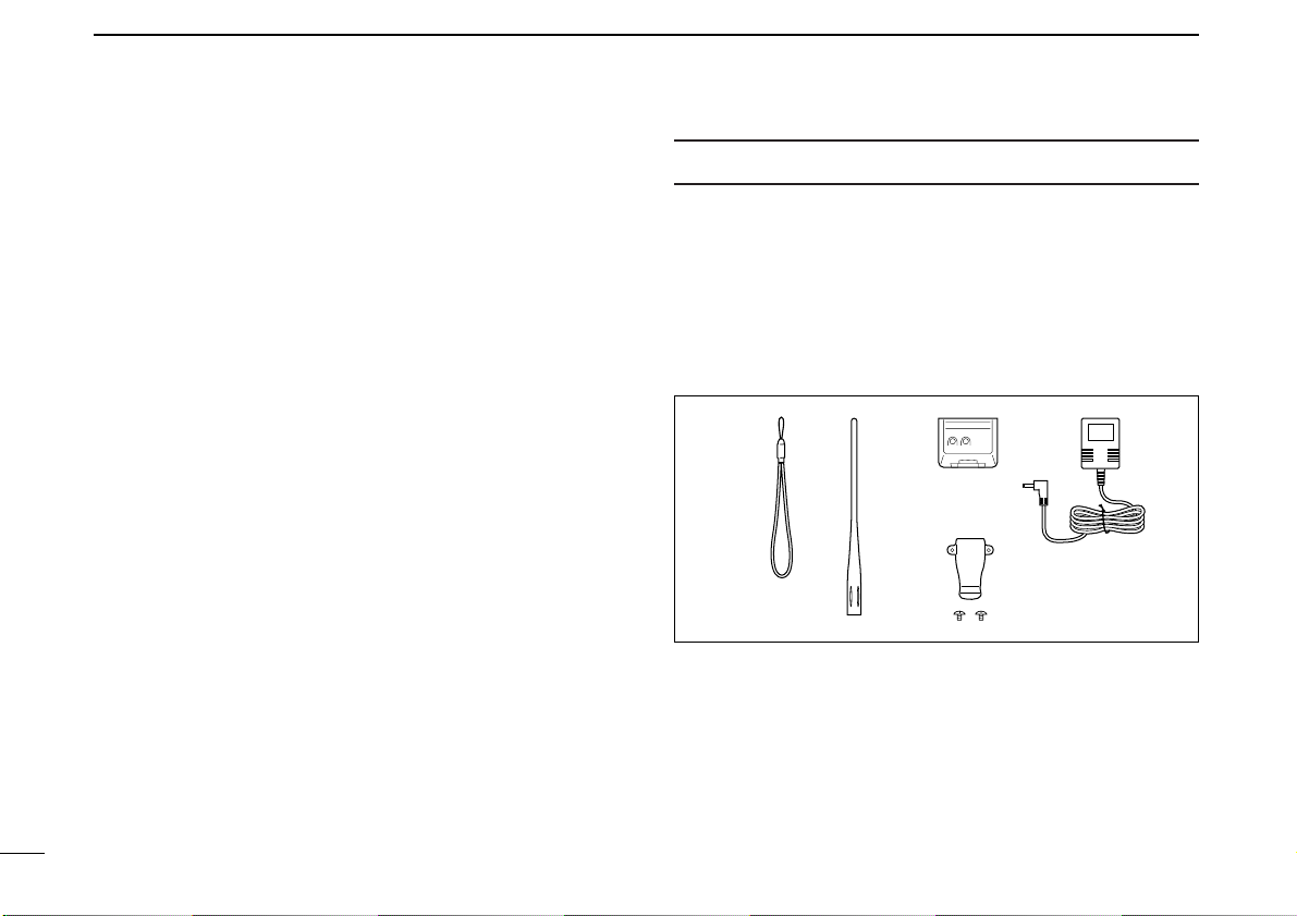
SUPPLIED ACCESSORIES ………………………………………… v
1ACCESSORY ATTACHMENT ………………………………… 1
■Antenna ………………………………………………………… 1
■Belt clip ………………………………………………………… 1
■Handstrap ……………………………………………………… 1
■Battery pack …………………………………………………… 1
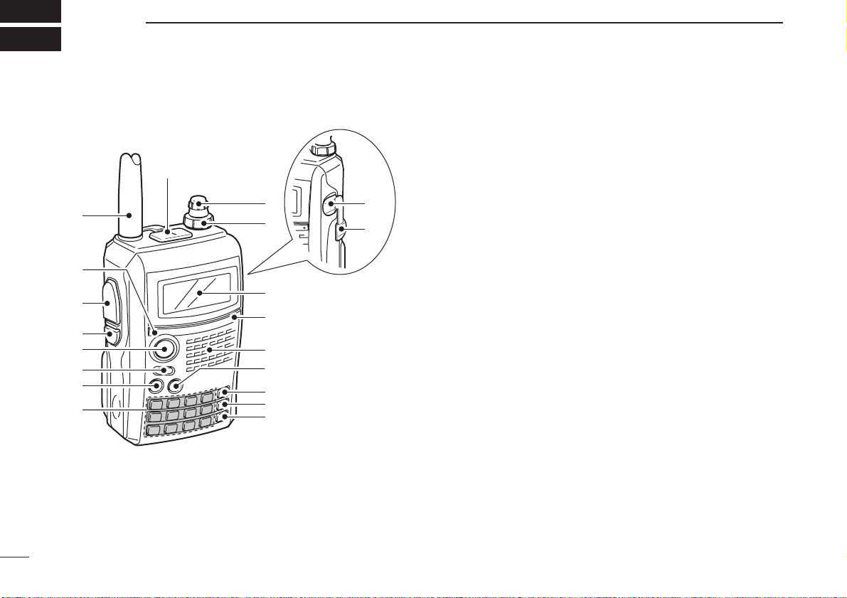
2PANEL DESCRIPTION ……………………………………… 2–7
■Front, top and side panels …………………………………… 2
■Function display ……………………………………………… 6
3BATTERY CHARGING ……………………………………… 8–13
■Caution ………………………………………………………… 8
■Regular charging ……………………………………………… 10
■Rapid charging ……………………………………………… 11
■Optional battery case ………………………………………… 12
■Battery information …………………………………………… 12
■External DC power operation ……………………………… 13
4FREQUENCY AND CHANNEL SETTING ……………… 14–19
■Main band selection ………………………………………… 14
■Mode selection ……………………………………………… 15
■Operating band selection …………………………………… 16
■Setting a tuning step ………………………………………… 18
■Setting a frequency …………………………………………… 18
5BASIC OPERATION ……………………………………… 20–28
■Receiving ……………………………………………………… 20
■Setting audio volume ………………………………………… 20
■Setting squelch level ………………………………………… 21
■Operating mode selection …………………………………… 21
■Monitor function ……………………………………………… 22
■Attenuator function …………………………………………… 22
■Band scope …………………………………………………… 23
■Transmitting …………………………………………………… 24
■Transmit power selection …………………………………… 24
■Lock function ………………………………………………… 25
■Dualwatch operation ………………………………………… 25
■TV channel operation ………………………………………… 28
6REPEATER AND DUPLEX OPERATIONS ……………… 29–33
■Repeater operation …………………………………………… 29
■Duplex operation ……………………………………………… 31
■Auto repeater function ……………………………………… 32
■1750 Hz tone ………………………………………………… 33
7DV MODE OPERATION
(Optional UT-121 is required for IC-91A) ………………… 34–63
■Digital mode operation ……………………………………… 34
■Call sign programming ……………………………………… 34
■Digital voice mode operation ………………………………… 38
■About D-STAR system ……………………………………… 40
■Digital repeater operation …………………………………… 41
■Received call sign …………………………………………… 46
■Copying the call sign ………………………………………… 48
■Break-in communication …………………………………… 51
■Message operation …………………………………………… 52
■Automatic reply function ……………………………………… 54
TABLE OF CONTENTS

iv
■EMR communication ………………………………………… 56
■Low-speed data communication …………………………… 56
■GPS operation ………………………………………………… 58
■Other functions for DV mode operation …………………… 62
8MEMORY/CALL CHANNELS …………………………… 64–73
■General description ………………………………………… 64
■Selecting a memory channel ………………………………… 64
■Selecting a call channel ……………………………………… 65
■Memory channel programming ……………………………… 66
■Memory bank setting ………………………………………… 67
■Memory bank selection ……………………………………… 68
■Programming memory/bank/scan name …………………… 69
■Selecting memory/bank name indication ………………… 70
■Copying memory/call contents ……………………………… 71
■Memory clearing ……………………………………………… 72
■Erasing/transferring bank contents ………………………… 73
9SCAN OPERATION ………………………………………… 74–81
■Scan types …………………………………………………… 74
■Full/band/programmed scan ………………………………… 75
■Scan edges programming …………………………………… 76
■Memory scan ………………………………………………… 77
■Memory bank scan …………………………………………… 78
■Skip channel/frequency setting ……………………………… 79
■Scan resume condition ……………………………………… 81
10 PRIORITY WATCH ………………………………………… 82–84
■Priority watch types ………………………………………… 82
■Priority watch operation ……………………………………… 83
11 MENU SCREEN OPERATION ………………………… 85–102
■General ………………………………………………………… 85
■MENU screen indication for B band ………………………… 86
■Menu list ……………………………………………………… 86
■Items list ……………………………………………………… 86
■Set mode items ……………………………………………… 88
■DV set mode items …………………………………………… 92
■Scan set mode items ………………………………………… 96
■DUP/TONE set mode items ………………………………… 97
■Display set mode items ……………………………………… 99
■Sounds set mode items …………………………………… 102
12 OTHER FUNCTIONS …………………………………… 103–118
■Programming a DTMF code ……………………………… 103
■Transmitting a DTMF code ………………………………… 104
■Clearing a DTMF memory ………………………………… 105
■Confirming a DTMF memory ……………………………… 105
■Setting DTMF transfer speed ……………………………… 106
■Tone frequency and DTCS code ………………………… 106
■Digital code and digital call sign setting ………………… 108
■Tone/DTCS squelch ………………………………………… 110
■Digital code/digital call sign squelch ……………………… 110
■Pocket beep function ……………………………………… 111
■DTCS polarity setting ……………………………………… 111
■Tone scan …………………………………………………… 112
■Beep tones …………………………………………………… 113
■Dial speed acceleration …………………………………… 113
■Key lock effect ……………………………………………… 113
■Weather channel operation ………………………………… 114
■Power save ………………………………………………… 115
■Auto power OFF …………………………………………… 116

■Auto power ON ……………………………………………… 116
■Time-out timer ……………………………………………… 116
■PTT lock ……………………………………………………… 116
■Cloning function …………………………………………… 117
■[MIC/SP] jacks ……………………………………………… 117
■Resetting …………………………………………………… 118
13 TROUBLESHOOTING ………………………………………… 119
14 SPECIFICATIONS ……………………………………… 120–121
15 OPTIONS ………………………………………………… 122–124
■Optional UT-121 installation ……………………………… 123
■Optional HM-75A
REMOTE CONTROL MICROPHONE
……… 124
SUPPLIED ACCESSORIES
The following accessories are supplied with the transceiver.
qHand strap ………………………………………………… 1
wAntenna …………………………………………………… 1
eBattery pack* ……………………………………………… 1
rBattery charger* …………………………………………… 1
tBelt clip (with screws) ………………………………… 1 set
*Not supplied with some versions.
re
q
t
w
v

1
1
ACCESSORY ATTACHMENT
1
■Antenna
Insert the supplied antenna into the
antenna connector and screw down
the antenna as shown at left.
NEVER carry the transceiver by hold-
ing the antenna.
KEEP the jack cover attached when
jack is not in use to protect the con-
nector from dust and moisture.
✔
For your information
Third-party antennas may increase transceiver perfor-
mance. An optional AD-92SMA
ANTENNA CONNECTOR
ADAPTER
is available to connect an antenna with a BNC
connector.
■Belt clip
■Handstrap
Slide the handstrap through the loop
on the top of the belt clip as illustrated
at left to facilitate carrying the
transceiver.
■Battery pack
Attach the Li-Ion battery pack (BP-217) or battery case (BP-
216) as illustrated below.
•Charge the Li-Ion battery pack before use. (pgs. 10, 11)
Battery pack/
Battery case
Latch
q
w
Handstrap
Supplied screws* *NOTE:
USE the supplied screws
only. Using screws lon-
ger than specified could
damage the transceiver.
Jack cover

2
PANEL DESCRIPTION
2
■Front, top and side panels
qANTENNA CONNECTOR (p. 1)
Connects the supplied antenna.
•An optional AD-92SMA adapter (p. 122) is available for connect-
ing an antenna with a BNC connector.
wTX/RX INDICATOR [TX/RX] (p. 24)
Lights green while receiving a signal or when the squelch
is open; lights red while transmitting.
ePTT SWITCH [PTT] (p. 24)
Push and hold to transmit, release to receive.
rSQUELCH KEY [SQL]
➥Push and hold to open the squelch temporarily and
monitor the operating frequency. (p. 22)
➥While pushing and holding this key, rotate [DIAL] to ad-
just the squelch level. (p. 21)
tMENU/LOCK KEY [MENU/LOCK]
➥Push to toggle menu screen indication ON and OFF.
(p. 85)
➥Push and hold for 1 sec. to toggle the lock function ON
and OFF. (p. 25)
yPOWER KEY [PWR]
Push and hold for 1 sec. to turn the transceiver power ON
and OFF.
uMAIN/DUAL KEY [MAIN/DUAL]
➥Push to select the main band between A and B bands.
(p. 26)
➥Push and hold for 1 sec. to toggle the dualwatch func-
tion ON and OFF. (p. 25)
iKEYPAD (pgs. 4, 5)
q
w
!5
Function display
Internal microphone
Speaker
!2
!6
e
r
t
y
u
i
!4
!3
o
!0
!1
!7

1-1-32 Kamiminami, Hirano-ku, Osaka 547-0003, Japan
New2001
A-6502H-1EX-qa
Printed in Japan
© 2006–2012 Icom Inc.
Printed on recycled paper with soy ink.
This manual suits for next models
1
Other Icom Transceiver manuals