Icom IC-78 User manual

INSTRUCTION MANUAL
HF TRANSCEIVER
i78
This device complies with Part 15 of the FCC rules. Operation is sub-
ject to the following two conditions: (1) This device may not cause
harmful interference, and (2) this device must accept any interference
received, including interference that may cause undesired operation.

i
IMPORTANT
READ THIS INSTRUCTION MANUAL
CAREFULLY before attempting to operate the
transceiver.
SAVE THIS INSTRUCTION MANUAL. This
manual contains important safety and operating in-
structions for the IC-78.
EXPLICIT DEFINITIONS
WORD DEFINITION
RDANGER! Personal death, serious injury or an
explosion may occur.
RWARNING! Personal injury, fire hazard or
electric shock may occur.
CAUTION Equipment damage may occur.
NOTE
Recommended for optimum use. No
risk of personal injury, fire or electric
shock.
PRECAUTIONS
RDANGER HIGH VOLTAGE! NEVER touch
an antenna connector during transmission. This may
result in an electrical shock or burn.
RWARNING! NEVER operate the transceiver
while driving a vehicle. Safe driving requires your full
attention—anything less may result in an accident.
RWARNING! NEVER operate the transceiver
with an earphone or other audio accessories at high
volume levels. Continuous high volume operation may
cause a ringing in your ears. If you experience ringing,
reduce the volume level or discontinue use.
RWARNING! NEVER connect the transceiver to
an AC outlet. This may pose a fire hazard or result in
an electric shock.
RWARNING! NEVER connect the transceiver to
a power source of more than 16 V DC such as a 24 V
DC. This could cause a fire or damage the transceiver.
RWARNING! NEVER reverse the DC power
cable polarity when connecting to a power source.
This could damage the transceiver.
RWARNING! NEVER cut the DC power cable
between the DC plug and fuse holder. If an incorrect
connection is made after cutting, the transceiver may
be damaged.
RWARNING! NEVER let metal, wire or other objects
touch any internal part or connectors on the rear panel of
the transceiver. This may result in an electric shock or this
could cause a fire or damage the transceiver.
RWARNING! NEVER operate or touch the
transceiver with wet hands. This may result in an elec-
tric shock or may damage the transceiver.
RWARNING! Immediately turn the transceiver
power OFF and remove the power cable if it emits an
abnormal odor, sound or smoke. Contact your Icom
dealer or distributor for advice.
CAUTION: NEVER expose the transceiver to rain,
snow or any liquids.
CAUTION: NEVER change the internal settings of
the transceiver. This may reduce transceiver perfor-
mance and/or damage to the transceiver.
CAUTION: NEVER place the transceiver where
normal operation of the vehicle may be hindered or
where it could cause bodily injury.
DO NOT operate the transceiver near unshielded
electrical blasting caps or in an explosive atmosphere.
DO NOT push the PTT when not actually desiring to
transmit.
Icom, Icom Inc. and Icom logo are registered trade-
marks of Icom Incorporated (Japan) in Japan, the Unit-
ed States, United Kingdom, Germany, France, Spain,
Russia, Australia, New Zealand, and/or other countries.
The transceiver comes with the following accessories.
Qty.
q DC power cable .................................................... 1
w Hand microphone (HM-36) ................................... 1
e Fuse (ATQ 25 A; for DC cable)............................. 2
r Fuse (FGB 4 A; internal use) ................................ 1
SUPPLIED ACCESSORIES
qw
er

ii
DO NOT use harsh solvents such as benzine or al-
cohol to clean the transceiver, as they will damage
the transceiver’s surfaces. If the transceiver becomes
dusty or dirty, wipe it clean with a soft, dry cloth.
DO NOT operate or place the transceiver in areas
with temperatures below –10°C (+14°F) or above
+60°C (+140°F).
Be aware that temperatures on a vehicle’s dashboard
can exceed +80°C (+176°F) in direct sunlight, result-
ing in permanent damage to the transceiver if left there
for extended periods.
DO NOT place the transceiver in excessively dusty
environments or in direct sunlight.
DO NOT place the transceiver against walls or put
anything on top of the transceiver. This will obstruct
heat dissipation.
Place the transceiver in a secure place to avoid inad-
vertent use by children.
During mobile operation, NEVER place the transceiv-
er where air bag deployment may be obstructed.
During mobile operation, DO NOT place the trans-
ceiver where hot or cold air blows directly onto it.
During mobile operation, DO NOT operate the trans-
ceiver without running the vehicle’s engine. When trans-
ceiver power is ON and your vehicle’s engine is OFF,
the vehicle’s battery will soon become exhausted.
Make sure the transceiver power is OFF before start-
ing the vehicle engine. This will avoid possible dam-
age to the transceiver by ignition voltage spikes.
During maritime mobile operation, keep the transceiver
and microphone as far away as possible from the
magnetic navigation compass to prevent erroneous
indications.
BE CAREFUL! The heatsink will become hot when
operating the transceiver continuously for long periods
of time.
BE CAREFUL! If a linear amplifier is connected,
set the transceiver’s RF output power to less than the
linear amplifier’s maximum input level, otherwise, the
linear amplifier will be damaged.
Use only supplied or optional Icom microphones.
Other manufacturer’s microphones have different
pin assignments, and connecting to the IC-78 may
damage the transceiver.
IMPORTANT .............................................................. i
EXPLICIT DEFINITIONS............................................ i
SUPPLIED ACCESSORIES....................................... i
PRECAUTIONS.......................................................i, ii
1 PANEL DESCRIPTION ................................... 1 – 6
Front panel ......................................................... 1
Function display ................................................. 3
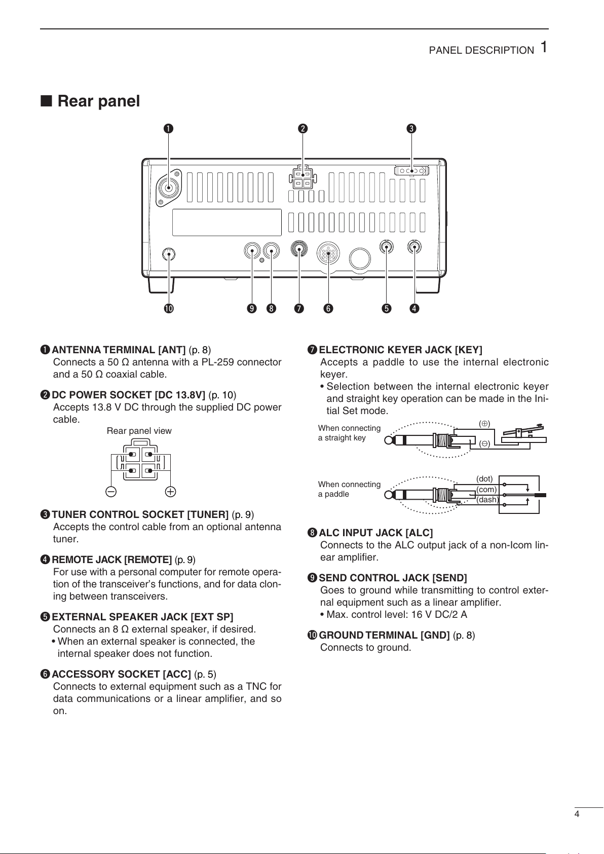
Rear panel.......................................................... 4
Microphone (HM-36) .......................................... 6
2 INSTALLATION AND CONNECTIONS ........ 7 – 11
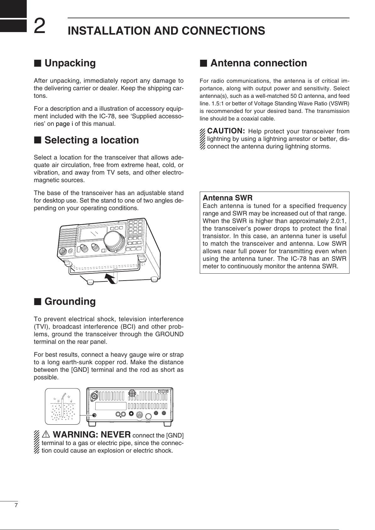
Unpacking .......................................................... 7
Selecting a location ............................................ 7
Grounding .......................................................... 7
Antenna connection ........................................... 7
Required connections ........................................ 8
Advanced connections ....................................... 9
Connecting the Power supply .......................... 10
External antenna tuners ................................... 11
3 OPERATION................................................. 12– 26
Selecting a channel.......................................... 12
Frequency indication ........................................ 13
Lock function .................................................... 13
Scan function ................................................... 13
Basic voice receive and transmit...................... 14
Mode selection ................................................. 14
RF gain and Squelch........................................ 14
Functions for transmit....................................... 15
Functions for receive........................................ 18
Filter selection .................................................. 20
Filter setting...................................................... 21
Functions for CW ............................................. 22
Functions for RTTY .......................................... 24
Channel name entry......................................... 26
4 SET MODE ................................................... 27– 32
General ............................................................ 27
Quick Set mode items ...................................... 28
Initial Set mode items....................................... 30
5 EXTRA FEATURES ..................................... 33– 35
Introduction ...................................................... 33
VFO operation.................................................. 33
2-Tone alarm operation.................................... 35
6 OPTION INSTALLATION............................. 36– 37
Opening the transceiver’s case........................ 36
Optional bracket and carrying handle .............. 36
CR-338 HIGH STABILITY CRYSTAL UNIT..... 37
Optional IF filters .............................................. 37
7 MAINTENANCE ........................................... 38– 39
Troubleshooting ............................................... 38
Fuse replacement ............................................ 39
Resetting the CPU ........................................... 39
8 REMOTE JACK INFORMATION ................. 40– 41
CI-V remote control .......................................... 40
Data cloning between transceivers .................. 41
9 SPECIFICATIONS............................................... 42
10 OPTIONS .................................................... 43– 44
TABLE OF CONTENTS

1
1
PANEL DESCRIPTION
Front panel
PWR
Speaker Function Display @1 @0 !9 !7
!5
!4
!6
!3
!2
!0
!8
!1
o
iuytre
w
q
qPOWER SWITCH [PWR]
Push to turn ON the power.
•First,conrmtheDCpowersupplyisON.Hold down for 1 second to turn OFF the power.
While holding down [SET], push [PWR] to enter
the Initial Set mode. (p. 27)
wMICROPHONE CONNECTOR [MIC]
Accepts the supplied or optional microphone.
•Seepage45forappropriatemicrophones.•Seepage7formicrophoneconnectorinformation.eHEADPHONE JACK [PHONES] (p. 9)
Accepts headphones.
•Whenheadphonesareconnected,theinternalorexternal speaker does not function.
rAF CONTROL [AF] (inner control)
Adjusts the audio output level.
tRF GAIN/SQUELCH CONTROL [RF/SQL]
(outer control, pp. 14, 30)
Adjusts the squelch threshold level. The squelch re-
moves noise output from the speaker (closed) when
no signal is received.
•Thesquelchisavailableforallmodes.•ThecontrolcanbesetasthesquelchplusRFgaincontrols or squelch control only (RF gain is fixed at
maximum) in the Initial Set mode.
yRIT CONTROL [RIT] (inner control, p. 18)
Shifts the receive frequency ±1.2 kHz for clear
reception of an off frequency signal.
•Rotatethecontrolclockwisetoincreasethefrequency, or counterclockwise to decrease the
frequency. “ ” is displayed on the display.
uIF SHIFT CONTROLS [SHIFT]
(outer control, p. 19)
Shifts the center frequency of the receiver’s IF
passband.
•Rotatethecontrolclockwisetoshiftthecenterfrequency higher, or counterclockwise to shift the
center frequency lower.
iLOCK SWITCH [LOCK] (p. 13)
Push to turn the dial lock function ON or OFF.
•ThediallockfunctionelectronicallylockstheChannelSelector.
oCHANNEL SELECTOR
Selects an operating channel, selects values in the
Quick/Initial Set mode items, and so on.
!0 PREAMP SWITCH [P.AMP] (p. 18)
Push to turn the preamp ON or OFF.
!1 FC SWITCH [CH]
Push to change the indication, channel name or
stored frequency. (p. 13)
This key action only for some versions.
Hold down for 1 second to enter the VFO mode.
(
p. 34
)
!2 MEMORY CHANNEL UP/DOWN SWITCHES
[qDN]/
[UP p]
Push to select the desired Memory channel.
(p. 12)
Hold down for 1 second to start scanning.
(p. 13)
Push to select the Quick/Initial Set mode items
while the Quick/Initial Set mode is selected.
(p. 27)
Push to select the character while editing the
channel name. (p. 26)

2
1
PANEL DESCRIPTION
!3 ATTENUATOR SWITCH [ATT] (p. 18)
Push to turn the 20 dB attenuator function ON or
OFF.
!4 TUNER SWITCH [TUNER] (p. 17)
Push to turn the antenna tuner function ON or
OFF.
Hold down for 1 second to manually tune the
tuner.
•Anoptionalantennatunermustbeconnected.•
When the tuner cannot tune the antenna, the tuning
circuit is automatically bypassed after 20 seconds.
!5 SET SWITCH [SET]
Hold down for 1 second to enter the Quick Set
mode. (p. 27)
Hold down [SET], then push [PWR] to enter the
Initial Set mode. (p. 27)
Push to change the meter function. (p. 15)
•PO:DisplaystherelativeRFoutputpower.•ALC:DisplaysALClevel.•SWR:DisplaystheSWRoverthetransmissionline.
!6 MIC COMPRESSOR SWITCH [COMP] (p. 16)
Turn the mic compressor function ON or OFF.
!7 KEYPAD
The Keypad can be used for several functions as
described below:
[0] to [9]
— To enter an operating channel number. (p. 12)
— Select a character when entering a channel
name. (p. 26)
[ENT]
— Direct channel number input. (p. 12)
[TXF]
— Transmit frequency display. (p. 13)
— Selects a space and changes the editing digit
when entering channel name. (p. 26)
!8 NOISE BLANKER SWITCH [NB] (p. 18)
Turns the noise blanker ON or OFF. The noise
blanker reduces pulse-type noise such as that
generated by automobile ignition systems. This
function is not effective against non pulse-type
noise.
Hold down [NB] for 1 second to enter the noise
blanker level setting mode.
!9 TONE SWITCH [TONE]
This key action may differ, depending on the
transceiver version.
Selects the Call channel and emits a distress
alarm tone from the speaker. (p. 35)
Transmits a distress alarm or alarm test signal
when held down for 1 second. (p. 35)
•Cancelsthedistressalarmtonesound,ordistressalarm transmission.
Directly selects the tuning step item in the Quick
Set mode.
No function is assigned, depending on the trans-
ceiver version.
@0 CALL SWITCH [CALL]
Push to select the Call channel.
•Pushagaintoreturntopreviouscondition.
@1 MODE SWITCH [MODE] (p. 14)
Push to change an operating mode.
•Holddown[MODE]for1secondduringSSBmodeto switch between LSB or USB.
•Holddown[MODE]for1secondduringCWorRTTY mode, to switch between CW and CW
reverse or RTTY and RTTY reverse. “ ” is
displayed on the display.

3
1PANEL DESCRIPTION
qLOCK ICON (p. 13)
Displays when the dial lock function is in use.
wRECEIVE ICON
Displays while receiving a signal or when the
squelch is open.
eTUNE ICON
Displays or disappears when the connected au-
tomatic tuner is tuned completely, depending on
connected antenna tuner type.
Blinks while tuning.
rTRANSMIT ICON
Displays while transmitting.
Blinks while transmit frequency is displayed.
tALARM ICON
This icon is displayed only some versions.
Displays while 2-tone alarm sounding or transmit-
ting
yFUNCTION ICONS
“P.AMP” is displayed when preamp is activated.
“ATT” is displayed when the RF attenuator is ac-
tivated.
“NB” is displayed when the Noise Blanker is acti-
vated.
“BK” is displayed when the semi break-in func-
tion is selected in the Quick Set mode.
“F-BK” is displayed when the full break-in func-
tion activates in CW mode. (p. 22)
“VOX” is displayed when the VOX function is se-
lected in the Quick Set mode.
“COM” is displayed when the speech compres-
sor activates in SSB mode.
“SCAN” is displayed during scanning.
•Blinkswhenscanispaused.uSIGNAL/SQL/RF-GAIN METER
Functions as an S-meter while receiving.
Functions as a Power, ALC or SWR meter while
transmitting. (p. 15)
iVFO/MEMORY ICON
“MEMO” is displayed during regular operation.
This icon is displayed only some versions.
“VFO” is displayed during VFO operation.
oCHANNEL NUMBER READOUT (p. 12)
Shows the selected channel number.
!0 BLANK ICON
Displays when no frequency programmed channel
is selected.
!1 SPLIT ICON (p. 12)
Displays when the duplex channel, in which differ-
ent frequencies between transmit and receive are
programmed, is selected.
!2 RIT ICON (p. 18)
Displays when the RIT function is in use.
!3 CHANNEL READOUT
Shows the memory names, or stored frequency of
the selected channel.
!4 REVERSE ICON (p. 14)
Displays when the CW reverse or RTTY reverse
mode is selected.
!5
WIDE/NARROW FILTER ICONS (pp. 20, 21)
“” is displayed when the wide IF filter is select-
ed.
“” is displayed when the narrow IF filter is se-
lected.
!6 MODE ICONS (p. 14)
Indicates the temporarily selected operating mode.
!6 !4
!5
uoi
r
e
w
!0
!3
!1
t
y
q
!2
Function display

4
1
PANEL DESCRIPTION
qANTENNA TERMINAL [ANT] (p. 8)
Connects a 50 Ωantenna with a PL-259 connector
and a 50 Ωcoaxial cable.
wDC POWER SOCKET [DC 13.8V] (p. 10)
Accepts 13.8 V DC through the supplied DC power
cable.
Rear panel view
eTUNER CONTROL SOCKET [TUNER] (p. 9)
Accepts the control cable from an optional antenna
tuner.
rREMOTE JACK [REMOTE] (p. 9)
For use with a personal computer for remote opera-
tion of the transceiver’s functions, and for data clon-
ing between transceivers.
tEXTERNAL SPEAKER JACK [EXT SP]
Connects an 8 Ωexternal speaker, if desired.
•Whenanexternalspeakerisconnected,theinternal speaker does not function.
yACCESSORY SOCKET [ACC] (p. 5)
Connects to external equipment such as a TNC for
data communications or a linear amplifier, and so
on.
uELECTRONIC KEYER JACK [KEY]
Accepts a paddle to use the internal electronic
keyer.
•Selectionbetweentheinternalelectronickeyerand straight key operation can be made in the Ini-
tial Set mode.
When connecting
a straight key
When connecting
a paddle
(dot)
(com)
(dash)
(⊕)
iALC INPUT JACK [ALC]
Connects to the ALC output jack of a non-Icom lin-
ear amplifier.
oSEND CONTROL JACK [SEND]
Goes to ground while transmitting to control exter-
nal equipment such as a linear amplifier.
•Max.controllevel:16VDC/2A!0 GROUND TERMINAL [GND] (p. 8)
Connects to ground.
qe
rtyuio!
0
w
Rear panel

5
1PANEL DESCRIPTION
ACC SOCKET INFORMATION
D
•ACCsocket•WhenconnectingtheACCconversioncable(OPC-599)
ACC 1
ACC 2
FSKK
AF
GND
SQLS
SEND
13.8 V
MOD
ALC
8 V
ALC
GND
NC
SEND
13.8 V
BAND
1
1
2
2
3
3
4
4
8
8
7
7
6
6
5
5
9
10 11 12
13
1
2
3
4
76
5
When the SEND terminal controls an inductive load (such as a relay), a counter-electromotive force can cause the
transceiver to malfunction or other damage. To prevent this, we recommend adding a switching diode, such as an “1SS133,”
on the load side of the circuit to the counter-electromotive force absorption. When the diode is added, a switching delay of
the relay may occur. Be sure to check its switching action before operation.
eSEND
i13.8V
ACC
socket
Relay
Switching diode To a non-Icom
linear amplifier
[Example]
ACC PIN # NAME DESCRIPTION SPECIFICATIONS
Rear panel
view
1234
8765
9
10 11 12
13
1 8 V Regulated 8 V output. Output voltage: 8 V ±0.3 V
Output current: Less than 10 mA
2 GND Connects to ground. —
Input/output pin. Ground level: –0.5 V to 0.8 V
3 SEND Goes to ground when transmitting. Input current: Less than 20 mA
When grounded, transmits.
4 BDT Data line. —
5 BAND Band voltage output.
6 ALC ALC voltage output. Control voltage: –4 V to 0 V
Input impedance:
More than 10 kΩ
7 NC — — —
8
13.8 V
13.8 V output when power is ON. Output current: Maximum 1 A
9 TKEY Key line. —
10 FSKK RTTY key input. Ground level: –0.5 V to 0.8 V
Input current: Less than 10 mA
11 MOD Modulation input.
Input impedance:
10 kΩ
Input level:
Approximately 100 mV rms
12 AF AF detector output.
Output impedance:
4.7 kΩ
Fixed, regardless of [AF] position. Output level: 100–300 mV rms
13 SQLS Squelch output. SQL open: Less than 0.3 V/5 mA
Goes to ground when squelch opens.
SQL closed:
More than 6.0 V/100 µA

6
1
PANEL DESCRIPTION
Microphone(HM-36)
•DESCRIPTIONqUP/DOWN SWITCHES [UP]/[DN]
Change the selected frequency or Memory chan-
nel.
•Holdingdowncontinuouslychangesthefrequency or Memory channel number.
•The[UP]/[DN]switchcanusedasapaddlekey.Set in the CW PADDL of the Initial Set mode.
(p. 31)
wPTT SWITCH
Hold down to transmit, release to receive. •MICROPHONECONNECTOR
(Front view)
CAUTION: DO NOT short pin 2 to ground as this
can damage the internal 8 V regulator. DC voltage is
also applied to pin 1 for microphone operation. Use
caution when using a non-Icom microphone.
q
w
yGND (PTT ground)
tPTT
rMain readout squelch switch
qMicrophone input
w+8 V DC output
eFrequency up/down
uGND
(Microphone ground)
iMain readout AF output
(varies with [AF])
•HM-36SCHEMATICDIAGRAM[MIC] FUNCTION DESCRIPTION
Pin No.
w+8 V DC output Maximum 10 mA
eFrequency up Ground
Frequency down Ground through 470 Ω
rSquelch open “Low” level
Squelch closed “High” level
+
q
w
ert
y
u
i
4700 pF
0.33 µF
Microphone
MIC
ELEMENT
22 kø
470 ø
DOWN UP
PTT
RECEIVE
TRANSMIT
Microphone Cable
Microphone Plug
1 kø
+
10 µF

2
7
INSTALLATION AND CONNECTIONS
Antenna connection
For radio communications, the antenna is of critical im-
portance, along with output power and sensitivity. Select
antenna(s), such as a well-matched 50 Ωantenna, and feed
line. 1.5:1 or better of Voltage Standing Wave Ratio (VSWR)
is recommended for your desired band. The transmission
line should be a coaxial cable.
CAUTION: Help protect your transceiver from
lightning by using a lightning arrestor or better, dis-
connect the antenna during lightning storms.
Unpacking
After unpacking, immediately report any damage to
the delivering carrier or dealer. Keep the shipping car-
tons.
For a description and a illustration of accessory equip-
ment included with the IC-78, see ‘Supplied accesso-
ries’ on page i of this manual.
Selecting a location
Select a location for the transceiver that allows ade-
quate air circulation, free from extreme heat, cold, or
vibration, and away from TV sets, and other electro-
magnetic sources.
The base of the transceiver has an adjustable stand
for desktop use. Set the stand to one of two angles de-
pending on your operating conditions.
Grounding
To prevent electrical shock, television interference
(TVI), broadcast interference (BCI) and other prob-
lems, ground the transceiver through the GROUND
terminal on the rear panel.
For best results, connect a heavy gauge wire or strap
to a long earth-sunk copper rod. Make the distance
between the [GND] terminal and the rod as short as
possible.
RWARNING: NEVER connect the [GND]
terminal to a gas or electric pipe, since the connec-
tion could cause an explosion or electric shock.
Antenna SWR
Each antenna is tuned for a specified frequency
range and SWR may be increased out of that range.
When the SWR is higher than approximately 2.0:1,
the transceiver’s power drops to protect the final
transistor. In this case, an antenna tuner is useful
to match the transceiver and antenna. Low SWR
allows near full power for transmitting even when
using the antenna tuner. The IC-78 has an SWR
meter to continuously monitor the antenna SWR.

8
2
INSTALLATION AND CONNECTIONS
Required connections
PWR
MICROPHONES (p. 43)
HM-36 SM-30 SM-50
GROUND (p. 7)
Use the heaviest gauge wire
or strap available and make
the connection as short as
possible.
Grounding prevents electrical
shocks, TVI and other prob-
lems.
ANTENNA
[Example]: 1.8–30 MHz bands
DC POWER SUPPLY
CW KEY
A straight key can be used when the
internal electronic keyer is turned
OFF in “CW PADDL” in the Initial Set
mode. (p. 31)
AH-710 PS-126
•Frontpanel•Rearpanel

9
2INSTALLATION AND CONNECTIONS
Advanced connections
PWR
MIC
The AFSK modulation signal can be
input from [MIC]. (p. 24)
HEADPHONES
•Frontpanel
ANTENNA
Connects a linear amplifier, etc.
[REMOTE] (pp. 40, 41)
Used for computer control and transceive operation,
and cloning operation between transceivers.
[SEND], [ALC]
Used for connecting a
non-Icom linear ampli-
fier.
EXTERNAL SPEAKER (p. 43)
ACC SOCKETS (p. 5)
AT-130, or
AH-4 (p. 43)
AH-2b
or long wire
AH-740
(p. 43)
with
SP-23
(Option)
•Rearpanel

10
2
INSTALLATION AND CONNECTIONS
Connecting the Power supply
Use an optional PS-126 DC POWER SUPPLY when
operating the IC-78 with AC power. Refer to the dia-
grams below.
CAUTION: Before connecting the DC power cable,
check the following important items. Make sure:
•The[POWER]switchisOFF.•Outputvoltageofthepowersourceis12to15Vwhen you use a non-Icom power supply.
•DCpowercablepolarityiscorrect.Red: Positive +terminal
Black: Negative _terminal
CONNECTING A VEHICLE BATTERY
CONNECTING A NON-ICOM DC POWER SUPPLY
1234
8765
9
10 11 12
13
DC power
socket
DC power supply AC outlet
AC cable
25 A fuses
Supplied
DC power cable
13.8 V 25 A
_+
black
red
+
_
CONNECTING THE PS-126 DC POWER SUPPLY
1234
8765
9
10 11 12
13
PS-126
Connect to an AC outlet
using the supplied AC cable.
DC power cable
DC power
socket
•RWARNING! NEVER connect to a battery
without using a DC fuse, otherwise a fire hazard
could occur or damage to the transceiver.
•NEVER connect the transceiver to a 24 V battery.
The transceiver may not receive well on some
frequencies when installed in a hybrid vehicle, or
any type of electric vehicle (fuel cell vehicle). This is
because vehicle’s electric components, such as the
inverter system, generate a lot of electric noise.
•DO NOT use a cigarette lighter socket as a power
source when operating in a vehicle.The plug may
cause voltage drops and ignition noise may be
superimposed onto transmit or receive audio.
•UsearubbergrommetwhenpassingtheDCpower cable through a metal plate to prevent a
short circuit.
12 V
battery
Supplied
DC power cable
+red
_black Crimp
Solder
Grommet
NOTE: Use terminals for
the cable connections.

11
2INSTALLATION AND CONNECTIONS
External antenna tuners
CONNECTING AN ANTENNA TUNER (p. 43)
Coaxial cable (from the tuner)
Long wire or optional AH-2b
Ground
IC-78 AT-130/AH-4
Control cable
Ground
CONNECTING THE AH-740 (p. 29)
OPC-2321
Coaxial cable (from the AH-740)
Ground
Ground
IC-78
AH-740
Coaxialcableandcontrolcableconnections
Rubber
vulcanizing
tape, then
electrical
tape.
Coaxial
cable
OPC-2321
Ground
strap
Vehicle chassis or body
Aboutthegroundstrapconnection•ThecoaxialcableissuppliedwiththeAH-740.The OPC-2321 Control cable is optional.
•SeetheAH-740instructionmanualfortheinstallationand connection details.

3
12
OPERATION
Selecting a channel
The transceiver has 99 memory channels. However,
the number of channels can be restricted in the Initial
Set mode (p. 30) depending on your needs. A total of
3 ways of channel selections are available to suit your
operating style.
Using the Channel Selector
D
Rotate the Channel Selector clockwise (channel num-
ber increases) or counterclockwise (channel number
decreases) to select desired channel.
This is the most useful way of channel selection.
DUsing up/down switches
Push
[UP p]
or [qDN] on the front panel or the mi-
crophone to select the desired channel.
This way is convenient when changing a small num-
ber of channels.
•Whenaduplexchannel(differentfrequenciesbe-
tween transmit and receive) is selected, “ ” is dis-
played.
Using the Keypad
D
Enter the number of the desired channel number using
the Keypad (0 to 9), then push [ENT].
This way is convenient for remembering the usage
and stored channel number, or when changing large a
number of channels.
•Whenaduplexchannel(differentfrequenciesbe-
tween transmit and receive) is selected, “ ” is dis-
played.
•Whenablankchannel(nofrequencyisprogrammed)is selected, “ ” is displayed.
Channel 1
Channel 2
Channel 99
Rotate the
channel selector
Push [DN]/[UP ]
to select a
channel
or
• Example 1— selecting channel 8
Push Push
Push Push
Blinks
• Example 2— selecting channel 25
Push
Blinks Blinks

13
3OPERATION
Frequency indication
Push [FC] to display the channel name or channel
frequency.
DTransmit frequency indication
Push [TXF] to display the transmit frequency instead
of the channel name or operating frequency.
When the transmit frequency is displayed, “ ”
blinks.
Lock function
The lock function electronically locks the Channel
Selector to prevent accidentally changing channels.
Push [LOCK] to turn the Lock function ON or OFF.
Before selecting a channel, turn OFF this function.
Scan function
The Scan function repeatedly scans programmed
channels. This function is convenient to wait for calls
on multiple channels.
qSet [RF/SQL] control to the center (12 o’clock) po-
sition (opening squelch), then rotate the control
clockwise to the position where the noise just dis-
appears.
wHold down
[UP p]
or [qDN] for 1 second to start
a Channel scan.
•The“SCAN”iconappears.eWhen a signal is received, the scan pauses on
that channel.
rPush
[UP p]
or [qDN] to cancel the scan.
NOTE: The scan resume operation (the action
after receiving a signal) can be set to “scan re-
sume” or “scan cancel” in the Initial Set mode
(p. 30).
[DN]/[UP ]
Appears when the Lock function is ON.
Appears while
scanning.
ch 5
ch 2 ch 3 ch 4
ch 6ch 7
BLANK
BLANK
ch 1
ch 99
Shallow
Deep
Recommended
position
Squelch control
Channel displayed
Frequency displayed
Push
Push
Push
Transmit frequency displayed
Blinks

14
3
OPERATION
Mode selection
The [RF/SQL] control adjusts either the RF gain or
the squelch. The action depends on the operating
mode and the condition of the RF/SQL item in the Ini-
tial Set mode (p. 30).
•[RF/SQL]controlpriority* The RF gain is set to maximum level when the [RF/SQL]
is set as [SQL] control.
The RF gain is used to adjust the receiver gain.
•ShallowrotationmovestheS-metertotherightindicatingthe signal strength which can be received.
The recommended position for RF gain is the 12
o’clock position since this sets RF gain to the max.
The SQUELCH removes noise output from the
speaker (closed condition) when no signal is received.
The squelch is available for the other modes.
•AsegmentisdisplayedintheS-metertoindicatetheS-meter squelch level. •Whensetasthe[RF/SQL]control•Whensetasthe[SQL]control•Whensetasthe[RF]controlRF gain and Squelch
Set mode setting SSB, CW, RTTY AM
rS (RF/SQL) RF/SQL RF/SQL
At (Auto) RF gain SQL*
Sq (SQL) SQL* SQL*
(default)
RF gain adjustable
range
Maximum RF gain
Squelch is open.
S-meter squelch
S-meter squelch
threshold
Squelch is open. S-meter squelch
S-meter squelch
threshold
Shallow Deep
Minimum RF gain
Adjustable range
Maximum RF gain
Basic voice receive and transmit
qCheck the following in advance:
Microphone is connected.
[AF] control is set to minimum position.
[RF/SQL] is set to center position (squelch open).
[RIT] control set to center position.
w
Selects the desired channel to be received with the
Channel Selector,
[UP p]
or
[qDN]
, or 10-key pad.
•
The S-meter shows signal strength when signal is received.
eAdjust [AF] to the desired audio level when receiv-
ing a signal.
rPush [MODE] to select the desired operation mode,
if the received signal is in a different mode.
tIf the bass or treble of the receive audio is too
strong, rotate [RIT] control to obtain clear audio.
(p. 18)
y
Push [TUNER] to tune the antenna tuner, if connected.
•The“TUNE”iconblinksfor1to2secondsforthersttuning on a channel.
uHold down [PTT] on the microphone, and speak
into the microphone at a normal voice level.
•TheRFmetershowstheoutputpoweraccordingtoyour voice level, when RF power meter is selected.
iRelease [PTT] to return to receive.
[RIT]
[AF]
[RF/SQL]
Microphone
connector
The following modes are available in the IC-78:
SSB (LSB/USB), CW, CW REV (CW reverse), RTTY,
RTTY REV (RTTY reverse) and AM.
Push [MODE] to select desired operation mode.
Hold down [MODE] for 1 second to change be-
tween USB and LSB, CW and CW reverse or
RTTY and RTTY reverse. (SSB, CW and RTTY
mode only)
•Theselectedmodeisindicatedinthefunctiondisplay.Note: The selected mode can be used for temporary
operation only.
OPERATING MODE SELECTION
Push
Hold down
for 1 sec.
USB LSB
CW CW
RTTY RTTY
AM
MODE
MODE

3OPERATION
15
Meter function
D
The bar meter in the function display acts as an S-
meter (for relative signal strength) during receive
and can be selected for one of three functions dur-
ing transmit.
•Push[SET]toselectthePO,ALCandSWRmetermode.•MeasuringSWRqConfirm that the output power is over 30 W.
w Push [SET] to select the SWR meter.
e Push [MODE] to select CW or RTTY operation.
•Keydownorpush[PTT]totransmit,thenreadthe actual SWR from the meter:
≤1.5; well matched antenna
≥1.5; check antenna or cable connection, and so on.
Display Measurement
Indication
PO Indicates the relative RF output power.
ALC
Indicates the ALC level. When the meter
movement shows the input signal level ex-
ceeds the allowable level, the ALC limits the
RF power. In such cases, reduce the micro-
phone gain (see above).
SWR
Indicates the SWR over the transmission line
.
Functions for transmit
Output power and microphone gain
D
•SettingoutputpowerqHold down [SET] for 1 second to select the Quick
Set mode.
wPush
[UP p]
or [qDN] to select “RF POWER”.
eRotate the main dial to select the desired output.
•Outputpowerisdisplayedin101steps(L,1–99andH) but is continuously selectable.
•AvailablepowerSSB/CW/RTTY: 2 (or less) to 100 W
AM: 2 (or less) to 35 W*
*Carrier power
Maximum output
power is selected. •SettingmicrophonegainMicrophone gain must be adjusted properly so that
your signal does not distort when transmitted.
qSelect SSB or AM mode.
wHold down [SET] for 1 second to enter the Quick
Set mode.
ePush
[UP p]
or [qDN] to select “MIC GAIN”.
rAdjust the mic gain while speaking into the micro-
phone, so that the ALC meter does not exceed the
ALC zone.
tPush [SET] to exit the Quick Set mode.
Microphone gain is
set to 50.
ALC zone
The best match is in this range.

16
3
OPERATION
Microphone compressor
D
IC-78 has a built-in, low distortion Mic compressor cir-
cuit. This circuit increases your average talk power in
SSB mode and is especially useful when the receiv-
ing station is having difficulty copying your signal.
qSelect USB or LSB mode.
wPush [COMP] switch to turn mic compressor ON.
•The“COM”iconisdisplayed.eConfirm the ALC level.
•Push[SET]toselecttheALCmeter.•Speakintothemicrophoneatanormalvoicelevel.•IftheALCmeterpeakpasttheALCzone,re-adjustthemic. gain. (p. 15)
•Besurethemicgainisintherangeof20to50.Note: When the ALC meter peaks above the ALC
zone, your transmitted voice may be distorted.
The VOX (Voice-operated Transmission) function
switches between transmit and receive with your
voice. This function provides an opportunity to input
log entries into your computer, etc. while operating.
qSelect “VOX” in the Quick Set mode.
•Holddown[SET]for1secondtoselecttheQuickSetmode.
•Push
[UP p]
or [qDN] to select “VOX”.
wRotate the Channel Selector to turn VOX function
ON.
eSelect “VOX GAIN” in the Quick Set mode.
•Push
[UP p]
or [qDN] to select “VOX”.
rWhile speaking into the microphone, adjust [VOX
GAIN] with the Channel Selector, until the trans-
ceiver is transmitting.
tSelect “VOX DELY” in the Quick Set mode.
•Push
[UP p]
or [qDN] to select “VOX Delay”
yWhile speaking into the microphone, adjust [VOX
DELY] as desired.
uSelect “ANTI-VOX” in the Quick Set mode.
•Push
[UP p]
or [qDN] one or more times to select
“AN VOX”
iIf the receive audio from the speaker switches the
transceiver to transmit during receive, adjust the
“ANTI-VOX” to the point where it has no effect.
oPush [SET] to exit the Quick Set mode.
VOX operation
D
Rotate the
channel selector
ONOFF
[COMP] switch
Adjust [MIC GAIN] so that the ALC
meter reads within the ALC zone.
ALC zone
Appears when
mic compressor
is activated.

3OPERATION
17
RDANGER HIGH VOLTAGE!
NEVER touch the antenna element while tuning or
transmitting. Always place it in a secure place.
NEVER operate the AT-130, AH-4 or AH-740 with-
out an antenna connected. The tuner and transceiv-
er will be damaged.
NEVER operate the AT-130, AH-4 or AH-740 if it is
not grounded.
Transmitting before tuning may damage the trans-
ceiver. Note that the AT-130 or AH-4 cannot tune
when using a 1⁄2 λlong wire or multiple of the oper-
ating frequency.
AT-130 or AH-4
The AT-130 or AH-4 matches the IC-78 to a long
wire antenna more than 7 m/23 ft long (3.5 MHz and
above).
•Seepage 11 for connection details.
•SeetheAntennatuner’sinstructionmanualforAT-130 or AH-4 installation and connection details.
AH-740
The optional AH-740 covers 2.5 to 30 MHz range with
a supplied whip antenna element. Or when using with
the optional NVIS kit, it covers 2.2 to 30 MHz range.
•Seepage 11 for connection details.
•SeetheAH-740instructionmanualfortheinstalla-
tion and connection details.
TUNER OPERATION
Tuning is required for each frequency. BE SURE to
re-tune the antenna before transmitting when you
change the frequency— even slightly.
•Tunertypesetting(p. 31)
qHold down [PWR] for 1 second to turn OFF the
power.
wEnter the Initial Set mode.
•Whileholdingdown[SET],turnpowerON.ePush
[UP p]
or [qDN] several times to select
[TUNER].
rRotate the Channel Selector to select connected
antenna tuner type.
•no:noantennatunerisselected.•4:AH-4orAH740isselected.•12:AT-120†is selected.
•13:AT-130isselected.yHold down [PWR] for 1 second to turn power
OFF.
uPush [PWR] to turn power ON again.
•MANUALTUNINGqSet the desired channel.
wHold down [TUNER] for 1 second to start tuning.
•“” blinks and “CW” appears while tuning.
[TUNER] switch
e“ ” lights constantly when tuning is complete.
•Whentheconnectedwirecannotbetuned,“” goes
out, the antenna tuner is bypassed and the antenna
wire is directly connected to the antenna connector on
the transceiver.
Tuning icon
Blinks: Tuning now
Appears: Tune is completed
Disappears: Tune cannot be not completed
(When AT-120†is connected, the indicator
disappears even when Tune is completed.)
rTo manually bypass the antenna tuner, push
[TUNER] to turn it OFF.
•WhenAT-130isconnected,startstuningagain.Optional external tuner operation
D
†No longer produced
Other manuals for IC-78
4
Table of contents
Other Icom Transceiver manuals

Icom
Icom IC-M710 User manual

Icom
Icom IC-2SAT User manual

Icom
Icom IC-F5020 Series User manual

Icom
Icom IC-04A User manual

Icom
Icom IC-U11 User manual

Icom
Icom IC-M87 User manual

Icom
Icom IC01271A/E User manual

Icom
Icom IC-F4160 SERIES User manual

Icom
Icom IC-DELTA100H User manual

Icom
Icom IP110H User manual