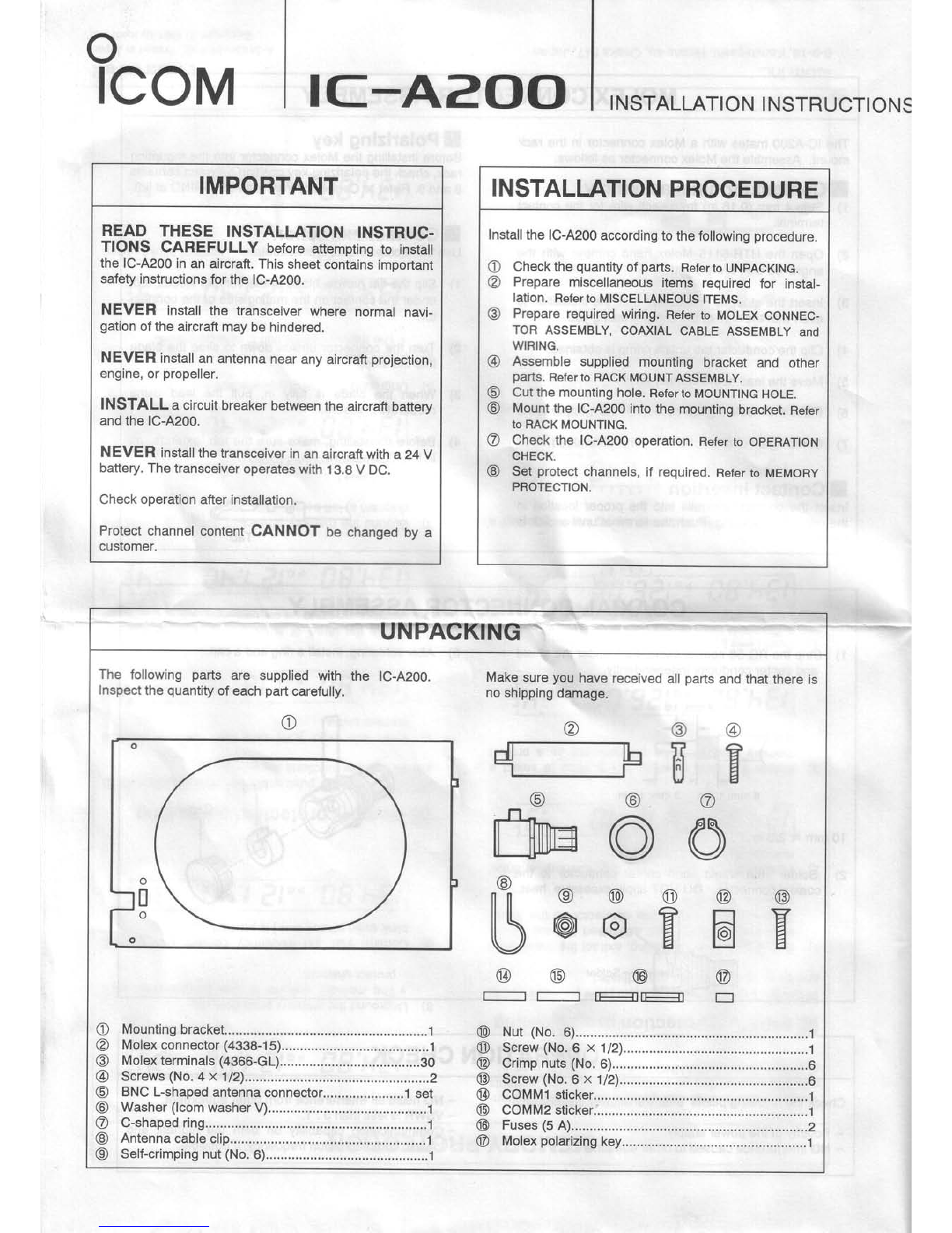
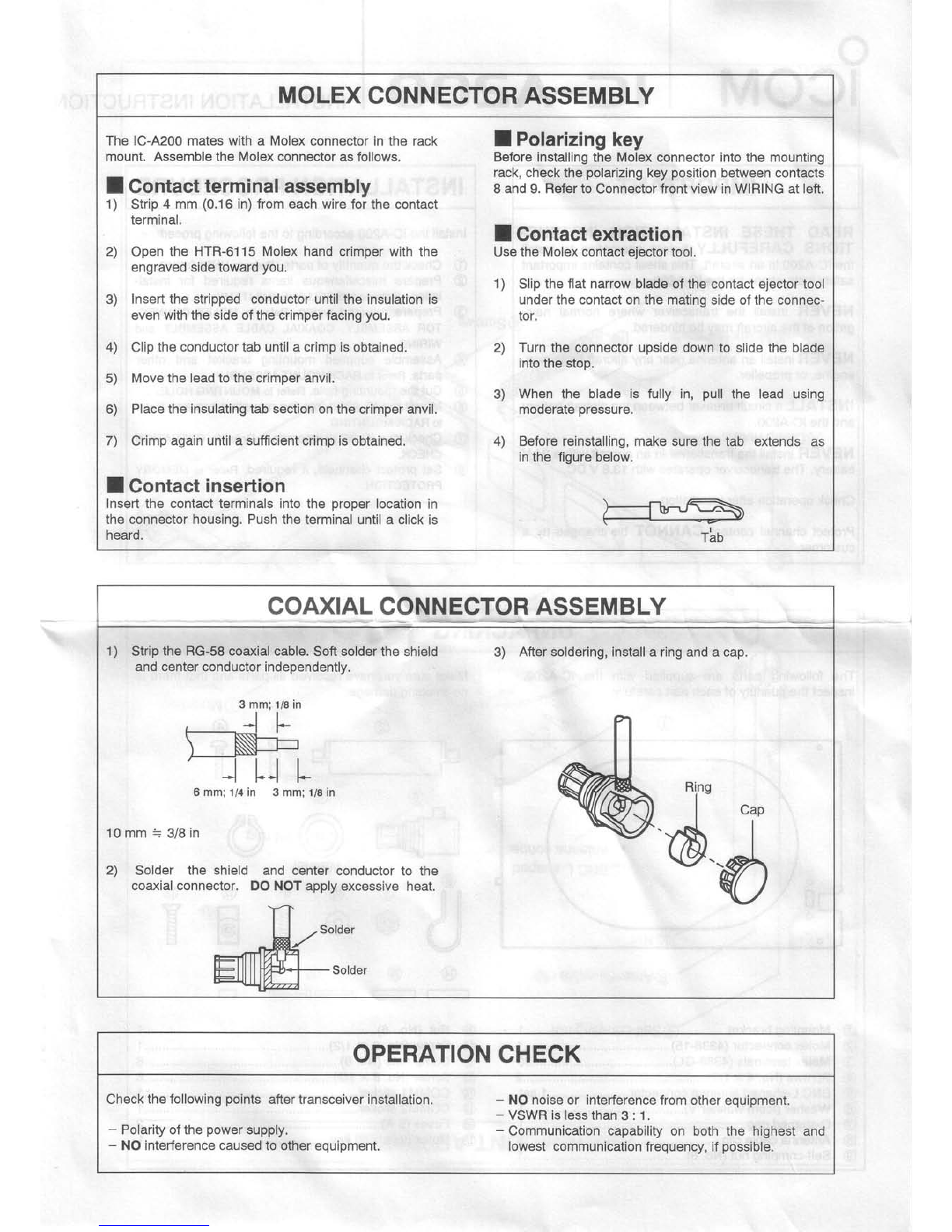
MOLEX
CONNECTORASSEMBLY
ThelC-A200mateswitha Molex
connectorinthe
mount.AssembletheMolexconnector
asfollows.
I Contact
terminal
assembly
1) Strip
4 mm
(0.16
in)fromeachwire
forthecontact
terminal.
2) Open
theHTR-6115Molexhandcrimperwith
the
engravedsidetoward
you.
3) lnsertthestrippedconductoruntil
theinsulationis
evenwiththesideofthecrimper
facing
you.
4) Clip
theconductortabuntilacrimpis
obtained.
5) Movetheleadtothecrimperanvil.
6) Placetheinsulatingtabsectiononthe
crimper
anvil.
7) Crimp
againuntilasufficientcrimp
isobtained.
I Gontact
insertion
Insertthecontactterminalsintotheproper
locationin
theconnectorhousing.Pushtheterminal
untilaclickis
heard.
I Polarizing
key
Before
installingthe Molexconnectorintothe mounting
rack,checkthepolarizing
keyposition
betweencontacts
8 and
9.Referto ConnectorfrontviewinWIRINGat left.
I Contact
extraction
Use
theMolexcontacteiector
tool.
1) Slip
theflatnarrowbladeofthe
contact
eiector
tool
underthecontactonthematingsideoftheconnec-
tor.
2) Turn
the
connectorupsidedowntoslidetheblade
intothestoD.
3) Whenthe bladeis fullyin, pull
the leadusing
moderate
pressure.
4) Beforereinstalling,
makesurethetab extends
as
inthe figure
below.
COAXIALCONNECTORASSEMBLY
1) Strip
the RG-58coaxial
cable.
Soft
solderthe shield 3) Aftersoldering,installa ringanda cap.
andcenterconductorindependently.
3mm:
1/8in
l*
tJt
o
mm;r/4in 3mm;r/s
in WffK Rins
-,1il1///M, l-
\K(Y/- l, I cap
10mm=3/8
in *\Z'-,"d. I
(/m l
2) Solder the shield and center
conductorto the \:2'#\
coaxiatconnector. Do NoT appty
excessiveheat. qL/
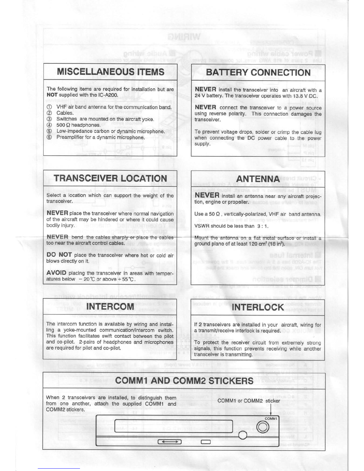
OPERATION
CHECK
Check
thefollowing
points
afiertransceiver
installation. - NOnoiseor interferencelrom
otherequipment.
- VSWRislessthan
3 :1.
- Polarityofthe
power
supply. - Communicationcapabilityon both the highestand
- NOinterferencecausedto otherequipment. lowestcommunicationfrequency,
ifpossible.