2001 NEW
ii
When your ship requires assistance, contact other
ships and the Coast Guard by sending a distress call
using digital selective calling on 2187.5 kHz.
IN CASE OF EMERGENCY
When immediate help is needed
qPush and hold [DISTRESS] for 5 sec. until the
short beeps become one long beep, to send the
distress call.
wAfter 2182 kHz is automatically selected (after an
acknowledgement call is received), push and hold
the PTT switch on the microphone and send the
following information.
1. “MAY DAY, MAY DAY, MAY DAY.”
2. “THIS IS. . . . . . . . . ” (name of ship)
3. “LOCATED AT . . . . ” (ship’s position)
4. Give the reason for the distress call.
5. Explain what assistance you need.
6. Give additional information:
• Ship type
• Ship length
• Ship color
• Number of people on-board
When potential problems exist
qPush [DSC] to select DSC watch mode, if neces-
sary.
wPush [MODE
SET
] to select DSC menu, rotate [CH]
to select “All ships” then push [ENT].
eFollow the guidance displayed on the LCD (bottom
line), to set up the category, traffic frequency and
calling frequency with [CH], [ENT] and keypad.
rPush and hold [CANCEL/CALL] for 1 sec. until the
short beeps become one long beep.
tAfter an acknowledgement call is received, trans-
mit the appropriate information using voice.
• DSC equipped ships may monitor your transmission.
FOREWORD................................................i
IMPORTANT .............................................. i
EXPLICIT DEFINITIONS ........................... i
PRECAUTIONS ......................................... i
IN CASE OF EMERGENCY ......................ii
TABLE OF CONTENTS ............................ ii
QUICK REFERENCE............................. I–V
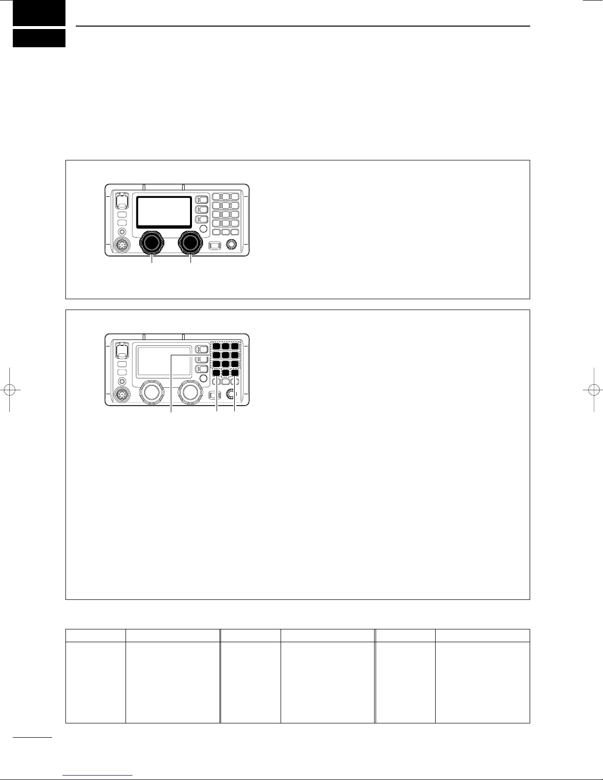
■How to set a Channel/Group .............. I
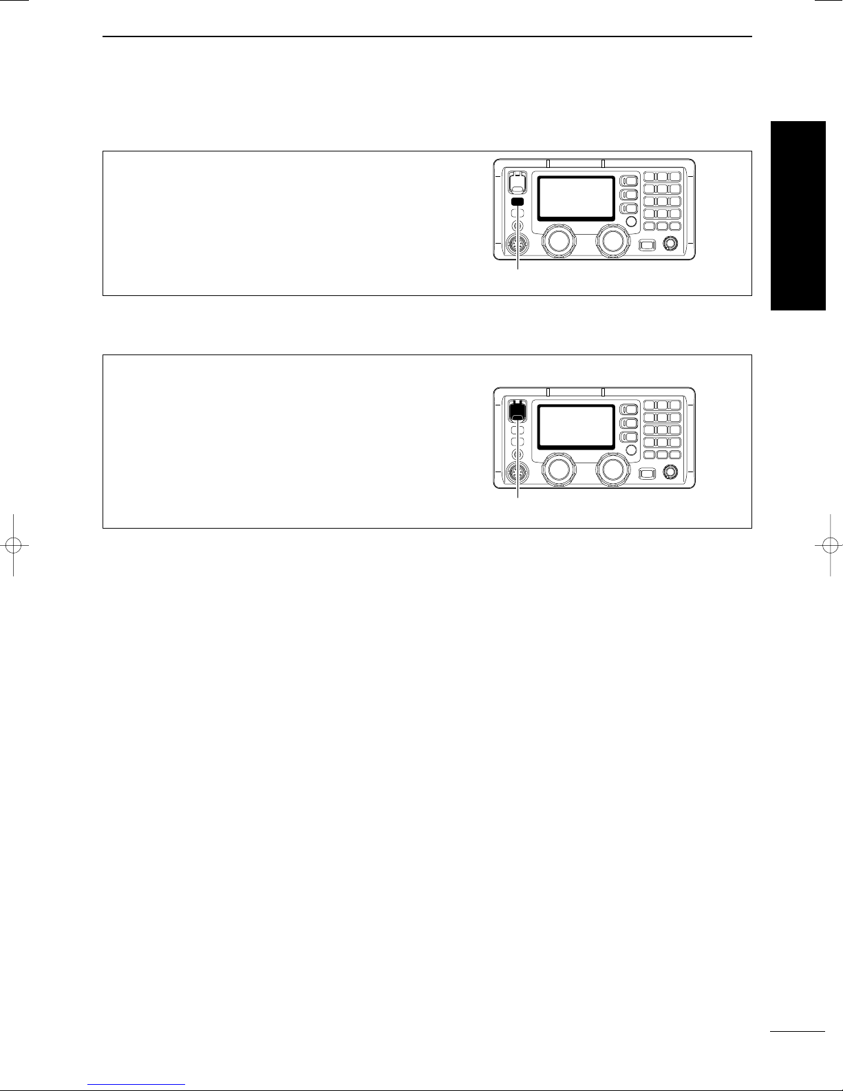
■Audio output/squelch adjustment ...... II
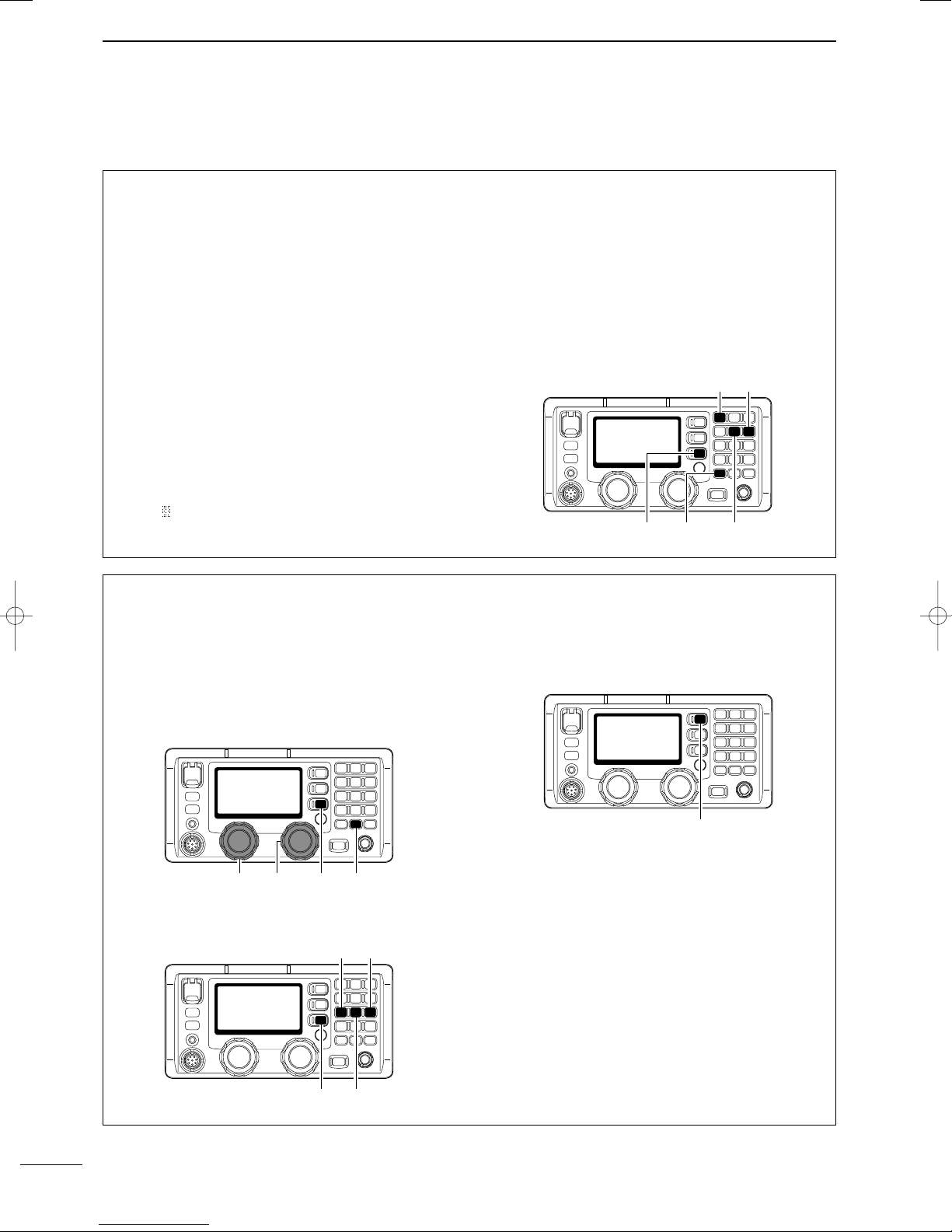
■Basic voice transmission and reception
.......................................................... III
■Receiving a DSC............................... IV
■Transmitting a distress call................ IV
1 OPERATING RULES AND GUIDELINES
............................................................... 1
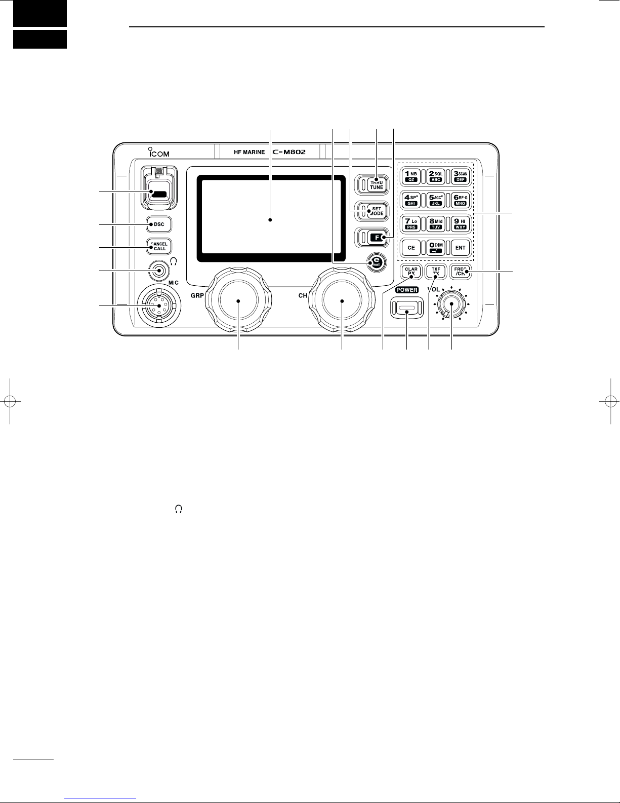
2 PANEL DESCRIPTION .................... 2–7
■Front panel— Controller .................... 2
■Front panel— Main unit ...................... 4
■Rear panel— Main unit ...................... 5
■Microphone (HM-135) ....................... 5
■LCD screen ....................................... 6
3 SETTING A CHANNEL .................... 8–9
■Selecting a channel ........................... 8
4 RECEIVE AND TRANSMIT .......... 10–13
■Basic voice transmit and receive .... 10
■Functions for transmit ...................... 10
■Functions for receive ....................... 11
■CW operation .................................. 12
■FSK operation ................................. 13
5 CHANNEL NAME PROGRAMMING
..................................................... 14
6 DSC PREPARATION ................... 15–16
■MMSI code programming ................ 15
■Position and time programming ....... 16
7 CALL PROCEDURE .................... 17–36
■Distress call ..................................... 17
■Distress call to ships ........................ 21
■Urgency call ..................................... 24
■Safety call ........................................ 28
■Routine call ...................................... 32
■Group call ........................................ 34
■Position request call ........................ 35
■Test call ........................................... 36
8 WHEN RECEIVING A CALL ........ 37–42
■To receive a DSC call ...................... 37
■Received information ....................... 38
■Deleting a memory .......................... 38
■Distress call ..................................... 39
■Distress relay call ............................ 39
■All ships call ..................................... 40
■Group call ........................................ 40
■Geographical area call .................... 40
■Individual call ................................... 41
■Position request call ........................ 42
9 MEMORY OPERATION ..................... 43
■Memory description ......................... 43
■Memory writing ................................ 43
■Memory reading/transmitting/deleting
......................................................... 43
10 DSC MENU OPERATION ............ 44–46
■General ............................................ 44
■ID input ............................................ 44
■Frequency input ............................... 45
■Verifying self-ID ............................... 46
■Memory reading/deleting ................. 46
11 E-MAIL OPERATION ......................... 47
■General ............................................ 47
■Operation ......................................... 47
12 SET MODE ................................... 48–52
■Quick set mode ............................... 48
■Initial set mode ................................ 49
13 CONNECTION AND INSTALLATION
....................................................... 53–62
■Supplied accessories ...................... 53
■Front panel connections ...................53
■Rear panel connections ................... 54
■Ground connection .......................... 55
■Power source .................................. 55
■Antenna ........................................... 56
■Mounting .......................................... 57
■Using the optional MB-75 ................ 58
■Transceiver dimensions ................... 59
■Fuse replacement ............................ 60
■Connector information ..................... 61
14 ANTENNA AND GROUNDING
CONSIDERATIONS ..................... 63–65
15 SPECIFICATIONS .............................. 66
16 TEMPLATE .................................. 67–70
■Remote controller (RC-25) .............. 67
■Speaker (SP-24) .............................. 69
17 OPTIONS ........................................... 71
TABLE OF CONTENTS
1
2
3
4
5
6
7
8
9
10
11
12
13
14
15
16
17
Quick Reference
IC-M802_USA.qxd 02.5.30 11:39 Page c