Icom IC-M602 User manual

INSTRUCTION MANUAL
iM602
VHF MARINE TRANSCEIVER
This device complies with Part 15 of the FCC rules. Operation is sub-
ject to the following two conditions: (1) This device may not cause
harmful interference, and (2) this device must accept any interference
received, including interference that may cause undesired operation.

FOREWORD
Thank you for purchasing this Icom product. The IC-
M602 V
HF MARINE TRANSCEIVER
is designed and built
with Icom’s state of the art technology and craftsman-
ship. With proper care, this product should provide you
with years of trouble-free operation.
We want to take a couple of moments of your time to
thank you for making the IC-M602 your radio of choice,
and hope you agree with Icom’s philosophy of “tech-
nology first.” Many hours of research and development
went into the design of your IC-M602.
D
FEATURES
❍Standard 4
×
8
″
flush mount design
❍Built-in DSC meets ITU Class D requirement
❍Rugged waterproof construction
❍Large LCD with dot matrix characters
❍Superior receiver performance
❍Optional COMMANDMICTM
(2 systems are connectable)
Icom, Icom Inc. and the logo are registered trademarks
of Icom Incorporated (Japan) in the United states, the United
Kingdom, Germany, France, Spain, Russia and/or other coun-
tries.
IMPORTANT
READ THIS INSTRUCTION MANUAL
CAREFULLY before attempting to operate the trans-
ceiver.
SAVE THIS INSTRUCTION MANUAL. This
manual contains important safety and operating in-
structions for the IC-M602.
CLEAN THE TRANSCEIVER AND MICROPHONE
THOROUGHLY WITH FRESH WATER after exposure to
water including salt water, otherwise, the keys and
switches may become inoperable due to salt crystallization.
i

ii
IN CASE OF EMERGENCY
If your vessel requires assistance, contact other vessels and
the Coast Guard by sending a distress call on Ch 16.
Or, transmit your distress call using digital selective calling on
Ch 70.
USING CHANNEL 16
DISTRESS CALL PROCEDURE
1. “MAYDAY MAYDAY MAYDAY.”
2. “THIS IS ...............” (name of vessel)
3. Your call sign or other indication of the vessel (AND 9-
digit DSC ID if you have one).
4. “LOCATED AT ...............” (your position)
5. The nature of the distress and assistance required.
6. Any other information which might facilitate the rescue.
USING DIGITAL SELECTIVE CALLING (Ch 70)
DISTRESS CALL PROCEDURE
1. While lifting up the switch cover, push and hold
[DISTRESS] for 5 sec. until you hear 5 short beeps
change to one long beep.
2. Wait for an acknowledgment from a coast station.
• Channel 16 is automatically selected.
3. Push and hold [PTT], then transmit the appropriate
information as at above.
WARNING
STICKER
NOTE
A WARNING STICKER is supplied with the transceiver.
To comply with FCC regulations, this sticker must be affixed in
such a location as to be readily seen from the operating con-
trols of the radio as in the diagram below. Make sure the cho-
sen location is clean and dry before applying the sticker. (p. 48)
EXAMPLE

iii
Icom requires the radio operator to meet the
FCC Requirements for Radio Frequency Expo-
sure. An omnidirectional antenna with gain not
greater than 9 dBi must be mounted a minimum
of 5 meters (measured from the lowest point of
the antenna) vertically above the main deck and all possible
personnel. This is the minimum safe separation distance esti-
mated to meet all RF exposure compliance requirements. This
5 meter distance is based on the FCC Safe Maximum Per-
missible Exposure (MPE) distance of 3 meters added to the
height of an adult (2 meters) and is appropriate for all vessels.
For watercraft without suitable structures, the antenna must
be mounted so as to maintain a minimum of 1 meter vertically
between the antenna, (measured from the lowest point of the
antenna), to the heads of all persons AND all persons must
stay outside of the 3 meter MPE radius.
Do not transmit with radio and antenna when persons are
within the MPE radius of the antenna, unless such persons
(such as driver or radio operator) are shielded from antenna
field by a grounded metallic barrier. The MPE Radius is the
minimum distance from the antenna axis that person should
maintain in order to avoid RF exposure higher than the allow-
able MPE level set by FCC.
FAILURE TO OBSERVE THESE LIMITS MAY ALLOW
THOSE WITHIN THE MPE RADIUS TO EXPERIENCE RF
RADIATION ABSORPTION WHICH EXCEEDS THE FCC
MAXIMUM PERMISSIBLE EXPOSURE (MPE) LIMIT.
IT IS THE RESPONSIBILITY OF THE RADIO OPERATOR
TO ENSURE THAT THE MAXIMUM PERMISSIBLE EXPO-
SURE LIMITS ARE OBSERVED AT ALL TIMES DURING
RADIO TRANSMISSION. THE RADIO OPERATOR IS TO
ENSURE THAT NO BYSTANDERS COME WITHIN THE
RADIUS OF THE MAXIMUM PERMISSIBLE EXPOSURE
LIMITS.
Determining MPE Radius
THE MAXIMUM PERMISSIBLE EXPOSURE (MPE) RA-
DIUS HAS BEEN ESTIMATED TO BE A RADIUS OF
ABOUT 3M PER OET BULLETIN 65 OF THE FCC.
THIS ESTIMATE IS MADE ASSUMING THE MAXIMUM
POWER OF THE RADIO AND ANTENNAS WITH A MAXI-
MUM GAIN OF 9dBi ARE USED FOR A SHIP MOUNTED
SYSTEM.
RADIO OPERATOR WARNING
WARNING

FOREWORD ............................................. i
IMPORTANT .............................................. i
IN CASE OF EMERGENCY ...................... ii
NOTE ........................................................ ii
RADIO OPERATOR WARNING ............... iii
TABLE OF CONTENTS ........................... iv
PRECAUTION .......................................... v
1 OPERATING RULES .................. 1
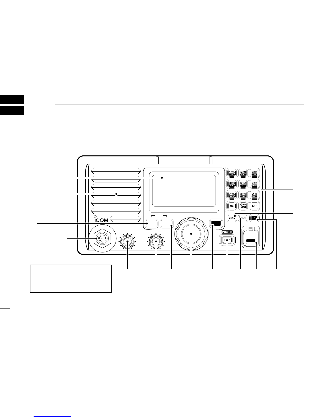
2 PANEL DESCRIPTION .......... 2 – 7
■Panel description ............................ 2
■Function display .............................. 6
■Microphone (HM-136) ..................... 7
3 BASIC OPERATION ............ 8 – 13
■Channel selection ........................... 8
■Receiving and transmitting ........... 10
■Call channel programming ............ 11
■Channel comments ....................... 11
■
Optional voice scrambler operation ... 13
4
DUALWATCH/TRI-WATCH
... 14–15
■Description .................................... 14
■Operation ...................................... 15
5 SCAN OPERATIONS ......... 16 – 17
■Scan types .................................... 16
■Setting tag channels ..................... 17
■Starting a scan .............................. 17
6 DSC OPERATION .............. 18 – 39
■MMSI code programming ............. 18
■Position and time programming .... 18
■Position indication ......................... 19
■Distress call .................................. 20
■Transmitting DSC calls ................. 22
■Setting the distress information .... 30
■DSC individual ID ......................... 31
■Receiving DSC calls ..................... 34
■DSC set mode .............................. 36
■Received messages ..................... 38
7 OTHER FUNCTIONS .......... 40–46
■Intercom operation ........................ 40
■Hailer operation ............................ 41
■Automatic fog horn ........................ 42
■Microphone lock function .............. 43
8 SET MODE ........................ 44 – 47
■Set mode programming ................ 44
■Set mode items ............................. 45
9 CONNECTIONS AND
MAINTENANCE ................. 48 – 53
■Supplied accessories .................... 48
■Antenna ........................................ 48
■Fuse replacement ......................... 48
■Cleaning ....................................... 48
■Connections .................................. 49
■Mounting the transceiver .............. 50
■Optional unit installation ............... 52
■Dimensions ................................... 53
10 TROUBLESHOOTING .............. 54
11 CHANNEL LIST ........................ 55
12 SPECIFICATIONS AND
OPTIONS ........................... 56 – 57
■Specifications ............................... 56
■Options ......................................... 57
13 HM-127 REMOTE-CONTROL
MICROPHONE ................... 58 – 70
■Panel description .......................... 58
■Function display ............................ 60
■HM-127 supplied accessories ...... 61
■Installation .................................... 62
■Channel selection ......................... 64
■Receiving and transmitting ........... 65
■RF attenuator function .................. 65
■Lock functions ............................... 66
■Display backlighting ...................... 66
■Monitor function ............................ 66
■Call channel programming ............ 67
■
Optional voice scrambler operation ... 67
■Starting a scan .............................. 68
■Setting tag channels ..................... 68
■Dualwatch/Tri-watch operation ..... 68
■Set mode programming ................ 69
■Intercom operation ........................ 70
■Channel comments ....................... 70
TEMPLATE
iv
TABLE OF CONTENTS 1
2
3
4
5
6
7
8
9
10
11
12
13

v
RWARNING! NEVER connect the transceiver to an AC
outlet. This may pose a fire hazard or result in an electric
shock.
CAUTION: Changes or modifications to this device, not ex-
pressly approved by Icom Inc., could void your authority to
operate this device under FCC regulations.
NEVER connect the transceiver to a power source of more
than 16 V DC or use reverse polarity. This will ruin the trans-
ceiver.
NEVER cut the DC power cable between the DC plug and
fuse holder. If an incorrect connection is made after cutting,
the transceiver may be damaged.
NEVER place the transceiver where normal operation of the
vessel may be hindered or where it could cause bodily injury.
KEEP the transceiver at least 3.3 ft (1 m) away from the
ship’s navigation compass.
DO NOT use or place the transceiver in areas with temper-
atures below –4°F (–20°C) or above +140°F (+60°C) or, in
areas subject to direct sunlight, such as the dashboard.
AVOID the use of chemical agents such as benzine or al-
cohol when cleaning, as they may damage the transceiver
surfaces.
BE CAREFUL! The transceiver rear panel will become
hot when operating continuously for long periods.
Place the transceiver in a secure place to avoid inadvertent
use by children.
BE CAREFUL! The transceiver and optional HM-127 em-
ploy waterproof construction, which corresponds to JIS wa-
terproof specification, Grade 7 (1 m/30 min.). However, once
the transceiver or microphone has been dropped, water-
proofing cannot be guaranteed due to the fact that the case
may be cracked, or the waterproof seal damaged, etc.
EXPLICIT DEFINITIONS
WORD DEFINITION
RRWARNING Personal injury, fire hazard or electric
shock may occur.
CAUTION Equipment damage may occur.
NOTE
If disregarded, inconvenience only. No
risk or personal injury, fire or electric
shock.
PRECAUTION

1
1
OPERATING RULES
DDPRIORITIES
•Read all rules and regulations pertaining to priorities and
keep an up-to-date copy handy. Safety and distress calls
take priority over all others.
•You must monitor Channel 16 when you are not operating
on another channel.
• False or fraudulent distress signals are prohibited and pun-
ishable by law.
DDPRIVACY
• Information overheard but not intended for you cannot law-
fully be used in any way.
• Indecent or profane language is prohibited.
DDRADIO LICENSES
(1) SHIP STATION LICENSE
You must have a current radio station license before using the
transceiver. It is unlawful to operate a ship station which is not
licensed.
Inquire through your dealer or the appropriate government
agency for a Ship-Radiotelephone license application. This
government-issued license states the call sign which is your
craft’s identification for radio purposes.
(2) OPERATOR’S LICENSE
A Restricted Radiotelephone Operator Permit is the license
most often held by small vessel radio operators when a radio
is not required for safety purposes.
The Restricted Radiotelephone Operator Permit must be
posted or kept with the operator. Only a licensed radio opera-
tor may operate a transceiver.
However, non-licensed individuals may talk over a transceiver
if a licensed operator starts, supervises, ends the call and
makes the necessary log entries.
Keep a copy of the current government rules and regulations
handy.
Radio license for boaters (U.S.A. only)
The Telecommunications Act of 1996 permits recreational
boaters to have and use a VHF marine radio, EPIRB, and
marine radar without having an FCC ship station license.
Boaters traveling on international voyages, having an HF
single sideband radiotelephone or marine satellite terminal,
or required to carry a marine radio under any other regula-
tion must still carry an FCC ship station license. For further
information, see the FCC Ship Radio Stations Fact Sheet.
1

PANEL DESCRIPTION
2
2
■Panel description
WATERPROOF
VOL
iM602
VHF MARINE
MIC
U/I/C 9
H/L
CH/WX
16
SQL
DISTRESS
Speaker
MIC connector
Function
display
q
wertyu oi!0
!1
!2
(Connect
HM-136 ONLY)
CAUTION: NEVER connect
other microphones here, such as
the optional HM-127, may cause
damage to the transceiver.

qTRANSMIT POWER SWITCH [H/L]
➥Toggles high or low power when pushed. (p. 10)
• Some channels are set to low power only.
➥While pushing this switch, some switches perform sec-
ondary functions.
wVOLUME CONTROL [VOL] (P. 10)
Adjusts the audio level.
eSQUELCH CONTROL [SQL] (P. 10)
Sets the squelch threshold level.
rCHANNEL SWITCH [CH/WX•U/I/C] (p. 9)
➥Selects and toggles the regular channels or weather
channel when pushed momentarily.
➥While pushing [H/L], push to select one of 3 regular
channels in sequence.
•International, U.S.A. and Canadian channels are available for
regular channels.
tCHANNEL SELECTOR [CHANNEL] (p. 10)
Rotate [CHANNEL] to select the operating channels, set
mode contents, etc.
yCHANNEL 16/CALL CHANNEL SWITCH [16•9]
➥Selects Channel 16 when pushed. (p. 8)
➥Selects call channel when pushed for 1 sec. (p. 8)
•“CALL” appears when call channel is selected.
➥Push for 3 sec. to enter call channel programming con-
dition when call channel is selected. (p. 11)
➥While pushing [H/L], enters memory name programming
condition. (p. 11)
➥While turning power ON, enters set mode when pushed
and held. (p. 44)
uPOWER SWITCH [POWER]
Push to turn the transceiver power ON or OFF.
iCLEAR SWITCH [CLR]
Push to cancel the entered function.
oDISTRESS SWITCH [DISTRESS] (p. 20)
Transmits distress call when pushed for 5 sec.
!0 FUNCTION SWITCH [F]
After pushing, activates the secondary functions.
•“F” appears when a secondary function can be accessed.
!1 DSC MENU SWITCH [MENU] (P. 18)
➥Toggles the DSC menu ON or OFF when pushed.
PANEL DESCRIPTION
3
2
2

4
2PANEL DESCRIPTION
!2 KEYPAD ➥Inputs the numeral “1” for channel number
input, etc.
➥Inputs “1,” “Q,” “Z,” “q,” “z” or space for channel
comment input.
➥After pushing [F], turns the dualwatch function
ON or OFF. (p. 15)
➥Inputs the numeral “2” for channel number
input, etc.
➥Inputs “2,” “A,” “B,” “C” “a,” “b” or “c” for chan-
nel comment input.
➥After pushing [F], turns the tri-watch function
ON or OFF. (p. 15)
➥Inputs the numeral “3” for channel number
input, etc.
➥Inputs “3,” “D,” “E,” “F,” “d,” “e” or “f” for channel
comment input.
➥After pushing [F], push this switch and rotate
[CHANNEL] to adjust the brightness of the
LCD and switch backlight.
➥Inputs the numeral “4” for channel number
input, etc.
➥Inputs “4,” “G,” “H,” “I,” “g,” “h” or “i” for channel
comment input.
➥After pushing [F], starts or stops the scan
function. (p. 17)

5
2
PANEL DESCRIPTION
➥Inputs the numeral “5” for channel number
input, etc.
➥Inputs “5,” “J,” “K,” “L,” “j,” “k” or “l” for channel
comment input.
➥After pushing [F], sets the displayed channel
as a tag (scanned) channel. (p.17)
➥While pushing [H/L], push for 3 sec. to clear all
tag channels. (p.17)
➥Inputs the numeral “6” for channel number
input, etc.
➥Inputs “6,” “M,” “N,” “O,” “m,” “n” or “o” for
channel comment input.
➥After pushing [F], turns the attenuator function
ON or OFF. (p. 10)
•“LOCAL” appears when the attenuator is in use.
➥Inputs the numeral “7” for channel number
input, etc.
➥Inputs “7,” “P,” “R,” “S,” “p,” “r” or “s” for chan-
nel comment input.
➥After pushing [F], turns the hailer function ON
or OFF. (p. 41)
➥Inputs the numeral “8” for channel number
input, etc.
➥Inputs “8,” “T,” “U,” “V,” “t,” “u” or “v” for channel
comment input.
➥After pushing [F], turns the auto fog horn func-
tion ON or OFF. (p. 43)
➥Inputs the numeral “9” for channel number
input, etc.
➥Inputs “9,” “W,” “X,” “Y,” “w,” “x” or “y” for chan-
nel comment input.
➥After pushing [F], turns the intercom function
ON or OFF. (p. 40)
➥Inputs the numeral “0” for channel number
input, etc.
➥Push for 1 sec. to edit “A” channel for channel
number input.
➥Inputs “0” and symbols (“–” “/” “.”) for channel
comment input.
➥After pushing [F], activates an optional voice
scrambler function. (p. 13)
•The optional voice scrambler function cannot be
used on Channel 16 and 70.
➥Fixes input of channel number and channel
comment, etc.
➥Clears entered digits and retrieves the previ-
ous frequency, channel or channel names dur-
ing setting.
2

■Function display
qBUSY/TRANSMIT INDICATOR (p. 10)
➥“BUSY” appears when receiving a signal or when the
squelch opens.
➥“TX” appears while transmitting.
wRECEIVER ATTENUATOR INDICATOR (p. 10)
“LOCAL” appears when the receiver attenuator is in use.
eSCRAMBLER INDICATOR (p. 13)
“SCRAM” appears when an optional voice scrambler is ac-
tivated.
rSCAN INDICATOR
➥Either “NORMAL SCAN” or “PRI-SCAN 16” scan
type appears while scanning. (p. 17)
➥“DUAL 16” appears during dualwatch; “TRI 16”
appears during tri-watch. (p. 15)
tPOSITION INDICATOR
➥Shows the GPS position data.
•“??” may blink every 2 sec. instead of position data when
the GPS position data is invalid. In such a case, the last
position data is held for up to 23.5 hours.
•“??” may blink every 2 sec. instead of position data 4
hours after the position data is input manually, up until
23.5 hours have past.
➥“No Position” appears when no GPS receiver is con-
nected and no position data is input manually.
yTIME ZONE INDICATOR
➥“Local” appears when the offset time data in the ‘Set
up’ menu is entered. (p. 36)
➥“No Time” appears when no GPS receiver is con-
nected and no time data is input manually.
uCHANNEL COMMENT INDICATOR
➥Channel comment appears if programmed. (p. 11)
➥“Lo Batt” flashes when the battery voltage drops to
approx. 10 V DC or below.
BUSY-25W---INT---CALL
LOCAL--DUP
SCRAM--TAG
NORMAL-SCAN
-34"34.506N
123"23.236W
Local--1:10--CALLING
w
q
e
t
y
r
!2!3 !1 !0 o
i
u
PANEL DESCRIPTION
6
2

7
2
PANEL DESCRIPTION
■Microphone (HM-136)
qPTT SWITCH [PTT] (p. 10)
Push and hold to transmit; release to receive.
wCHANNEL UP/DOWN SWITCHES [YY]/[ZZ](P. 10)
Push either switch to change the operating channel, set
mode contents, etc.
eCHANNEL 16/CALL CHANNEL SWITCH [16/9]
➥Push to select Channel 16; push for 1 sec. to Channel 9.
(p. 8)
➥
While pushing [16/9], turn power ON to toggle the lock
function ON or OFF. (p. 43)
Speaker
Microphone
w
q
e
16/9
iCHANNEL NUMBER READOUT
➥Indicates the selected operating channel number.
“A” appears when a simplex channel is selected. (p. 9)
“b” appears when a receive only channel for a Canadian
channel group is selected.
➥“F” appears when [F] switch is pushed.
oCALL CHANNEL INDICATOR (p. 8)
“CALL” appears when the call channel is selected.
!0 CHANNEL GROUP INDICATOR (p. 9)
Indicates whether an International “INT,” U.S.A. “USA,”
Canadian “CAN” or weather “WX” channel is selected.
!1 DUPLEX INDICATOR (p. 9)
Appears when a duplex channel is selected.
!2 POWER INDICATOR (p. 10)
➥“25W” appears when high power is selected.
➥“1W” appears when low power is selected.
!3 TAG CHANNEL INDICATOR (p. 17)
Appears when a tag channel is selected.
2

8
3BASIC OPERATION
■Channel selection
DDChannel 16
Channel 16 is the distress and safety channel. It is used for
establishing initial contact with another station and for emer-
gency communications. Channel 16 is monitored during both
dualwatch and tri-watch. While standing by, you must monitor
Channel 16.
➥Push [16•9] momentarily to select Channel 16.
➥Push [CH/WX•U/I/C] to return to the condition before se-
lecting Channel 16, or rotate [CHANNEL] to select operat-
ing channel.
DDChannel 9 (Call channel)
Each regular channel group has a separate leisure-use call
channel. The call channel is monitored during tri-watch. The
call channels can be programmed (p. 11) and are used to
store your most often used channels in each channel group
for quick recall.
➥Push [16•9] for 1 sec. to select the call channel of the se-
lected channel group.
•“CALL” and call channel number appear.
• Each channel group may have an independent call channel after
programming a call channel.
➥Push [CH/WX•U/I/C] to return to the condition before se-
lecting the call channel,or rotate [CHANNEL] to select an
operating channel.
Push for
1 sec.
9
16
BUSY-25W---INT---CALL
LOCAL--DUP
SCRAM--TAG
NORMAL-SCAN
-34"34.206N
123"23.236W
--UTC-10:10--CALLING
Push
9
16
BUSY-25W---INT---CALL
LOCAL--DUP
SCRAM--TAG
NORMAL-SCAN
-34"34.206N
123"23.236W
--UTC-10:10--CALLING

3
BASIC OPERATION
9
DDU.S.A., Canadian and International channels
There are 57 U.S.A., 61 Canadian and 57 International chan-
nels. These channel groups may be specified for the operat-
ing area.
qPush [CH/WX•U/I/C] to select a regular channel.
• If a weather channel appears, push [CH/WX•U/I/C] again.
wWhile pushing [H/L], push [CH/WX•U/I/C] to change the
channel group, if necessary.
•U.S.A., International (INT) and Canadian channels can be se-
lected in sequence.
eRotate [CHANNEL] to select a channel.
•“DUP” appears for duplex channels.
• “A” appears for simplex channels.
DDWeather channels
There are 10 weather channels. Used for monitoring weather
channels from the NOAA (National Oceanographic and At-
mospheric Administration) broadcasts.
The transceiver can detect a weather alert tone on the se-
lected weather channel while receiving that channel, during
standby on a regular channel or while scanning. See
“Weather alert” on p. 45.
qPush [CH/WX•U/I/C] once or twice to select a weather
channel.
•“WX” appears when a weather channel is selected.
• “WX ALERT” appears when the weather alert function is in use.
(p. 45)
wRotate [CHANNEL] to select a channel.
Push once or twice
When weather alert is OFF. When weather alert is ON.
WXALERT
WX
CH/WX
Push +
U.S.A. channels
H/L CH/WX
Canadian channels
CAN
International channels
INT
DUP
USA
3

■Receiving and transmitting
CAUTION: Transmitting without an antenna may dam-
age the transceiver.
qPush [POWER] to turn power ON.
wSet the audio and squelch levels.
➥Rotate [SQL] fully counterclockwise in advance.
➥Rotate [VOL] to adjust the audio output level.
➥Rotate [SQL] clockwise until the noise disappears.
eTo change the channel group, push [CH/WX•U/I/C] while
pushing [H/L]. (p. 9)
rRotate [CHANNEL] or push [Y]/[Z] on the microphone to
select the desired channel.
• When receiving a signal, “BUSY” appears and audio is emitted
from the speaker.
• Further adjustment of [VOL] may be necessary at this point.
• Use the optional voice scrambler function for privacy. (p. 13)
tPush [F], then push [6 LO/DX] to turn the receive attenua-
tor function ON or OFF if necessary.
•“LOCAL” appears when the receive attenuator is in use.
yPush [H/L] to select the output power if necessary.
•“25W” or “1W” appears when high or low power is selected, re-
spectively.
•Choose low power to conserve power, choose high power for
longer distance communications.
• Some channels are for low power only.
uPush and hold [PTT] to transmit, then speak into the mi-
crophone.
•“TX” appears.
• Channel 70 cannot be used for transmission.
Simplex channels, 3, 21, 23, 61, 64, 81, 82 and 83 CAN-
NOT be lawfully used by the general public in U.S.A. wa-
ters.
iRelease [PTT] to receive.
IMPORTANT: To maximize the readability of your trans-
mitted signal, pause a few sec. after pushing [PTT], hold
the microphone 1 to 2 inches (2.5 to 5 cm) from your
mouth and speak at a normal voice level.
WATERPROOF
VOL
iM602
VHF MARINE
MIC
U/I/C 9
SQL
16/9
w
et
qrr
yui
3BASIC OPERATION
10

3
BASIC OPERATION
11
■Call channel programming
The call channel is used to select Channel 9, however, you
can program your most often-used channels in each channel
group for quick recall.
qWhile pushing [H/L], push [CH/WX•U/I/C] one or more
times to select the desired channel group (U.S.A., Interna-
tional, Canada) to be programmed.
wPush [16•9] for 1 sec. to select the call channel of the se-
lected channel group.
•“CALL” and call channel number appear.
ePush [16•9] again for 3 sec. (until a long beep changes to
2 short beeps) to enter call
channel programming con-
dition.
•Channel number starts blink-
ing.
rRotate [CHANNEL] to se-
lect the desired channel.
tPush [16•9] to program the
displayed channel as the
call channel.
•Push [CH/WX•U/I/C] to can-
cel.
•The channel number stops
blinking.
■Channel comments
Memory channels can be tagged with alphanumeric names
of up to 10 characters each.
Capital letters, small letters, numerals, some symbols (- . /)
and space can be used.
qSelect the desired memory channel.
• Cancel dual watch, tri-watch or scan in advance.
wWhile pushing [H/L], push [16•9] to edit the channel com-
ment.
•A cursor appears and blinks.
ePush the appropriate key several times to enter the de-
sired character.
• See the table on page 12 for available characters.
• Rotate [CHANNEL] or push [Y]/[Z] on the microphone to move
the cursor.
rPush [ENT] to input and set the comment.
• Push [CLR] to cancel.
• The cursor disappears.
tRepeat steps qto rto program other channel com-
ments, if desired.
BUSYBUSY-25W25W------INTINT------CALLCALL
LOCAL--DUPLOCAL--DUP
SCRAMSCRAM----TAGTAG
NORMAL-SCANNORMAL-SCAN
-34"34.206N34"34.206N
123"23.236W123"23.236W
----UTCUTC-10:1010:10----CALLINGCALLING
BUSYBUSY-25W25W------INTINT------CALLCALL
LOCAL--LOCAL--DUPDUP
SCRAMSCRAM----TAGTAG
NORMAL-SCANNORMAL-SCAN
-34"34.206N34"34.206N
123"23.236W123"23.236W
----UTCUTC-10:1010:10------INTLINTL
BUSY-BUSY-25W25W------INTINT------CALLCALL
LOCAL--LOCAL--DUPDUP
SCRAMSCRAM----TAGTAG
NORMAL-SCANNORMAL-SCAN
-34"34.206N34"34.206N
123"23.236W123"23.236W
----UTCUTC-10:1010:10-PLEASURELEASURE
3

12
3BASIC OPERATION
KEY CHARACTERS KEY CHARACTERS
1
2
3
4
5
Q
A
D
G
J
Z
B
E
H
K
q
C
F
I
L
z(space)
a
d
g
j
b
e
h
k
c
f
i
l
6
7
8
9
0
M
P
T
W
-
N
R
U
X
/
O
S
V
Y
.
mno
p
t
r
u
x
s
v
y
•Available characters

13
3
BASIC OPERATION
■Optional voice scrambler operation
DDActivating the scrambler
The optional voice scrambler provides private communica-
tions. In order to receive or send scrambled transmissions
you must first activate the scrambler function. To activate the
function, an optional UT-112 is necessary. See p. 47 for set-
ting the scrambler unit. Ask your dealer for details.
The scrambler function automatically turns OFF when
Channel 16 or 70 is selected.
q
Select an operating channel other than Channel 16 and 70.
wPush [F], then push [0 SCRM] to turn the optional scram-
bler function ON.
• “SCRAM” appears.
eTo turn the scrambler function OFF, repeat step w.
• “SCRAM” disappears.
DDProgramming scrambler codes
There are 32 codes (1 to 32) available for programming when
the optional UT-112 is installed. In order to understand one
another, all transceivers in your group must have the same
scramble code. This function may not be available depend-
ing on dealer setting.
qTurn power OFF.
wWhile pushing [16•9], turn power ON to enter set mode.
eAfter the display appears, release [16•9].
rRotate [CHANNEL] to select the “Scrambler Code,”
push [ENT].
tRotate [CHANNEL] to select the desired scrambler code.
yPush [ENT] to set and exit the scrambler code item.
uRotate [CHANNEL] to select “Exit,” then push [ENT] to
exit set mode.
Enter set mode
POWER
+
9
16
ENT ENT
Select item
then push
Select code
then push
Scrambler Code
˘9
˘7
--Set Mode--
˘5
˘6
˘8
˘<ENT˘OK>
˘Scan Type
˘Scan Timer
--Set Mode--
˘Internal Speaker
˘Contrast
˘Beep
˘Dual/Tri COMMANDMIC
˘WX Alert
˘Internal Speaker
˘Contrast
--Set Mode--
˘Scrambler Code
˘Exit
˘Scrambler Type
˘Foghorn Frequency
˘RF Attenuator
[Example]: Programming scrambler code 8.
3

14
4DUAL WATCH/TRI-WATCH
■Description
Dualwatch monitors Channel 16 while you are receiving an-
other channel; tri-watch monitors Channel 16 and the call
channel while receiving another channel.
DUALWATCH/TRI-WATCH SIMULATION
• If a signal is received on Channel 16, dualwatch/tri-watch pauses on Channel 16 until the signal disappears.
• If a signal is received on the call channel during tri-watch, tri-watch becomes dualwatch until the signal disappears.
• To transmit on the selected channel during dualwatch/tri-watch, push and hold [PTT].
Call channel
Dualwatch Tri-watch
Other manuals for IC-M602
4
Table of contents
Other Icom Transceiver manuals