3
Section 2PROGRAMMABLE KEY FUNCTIONS
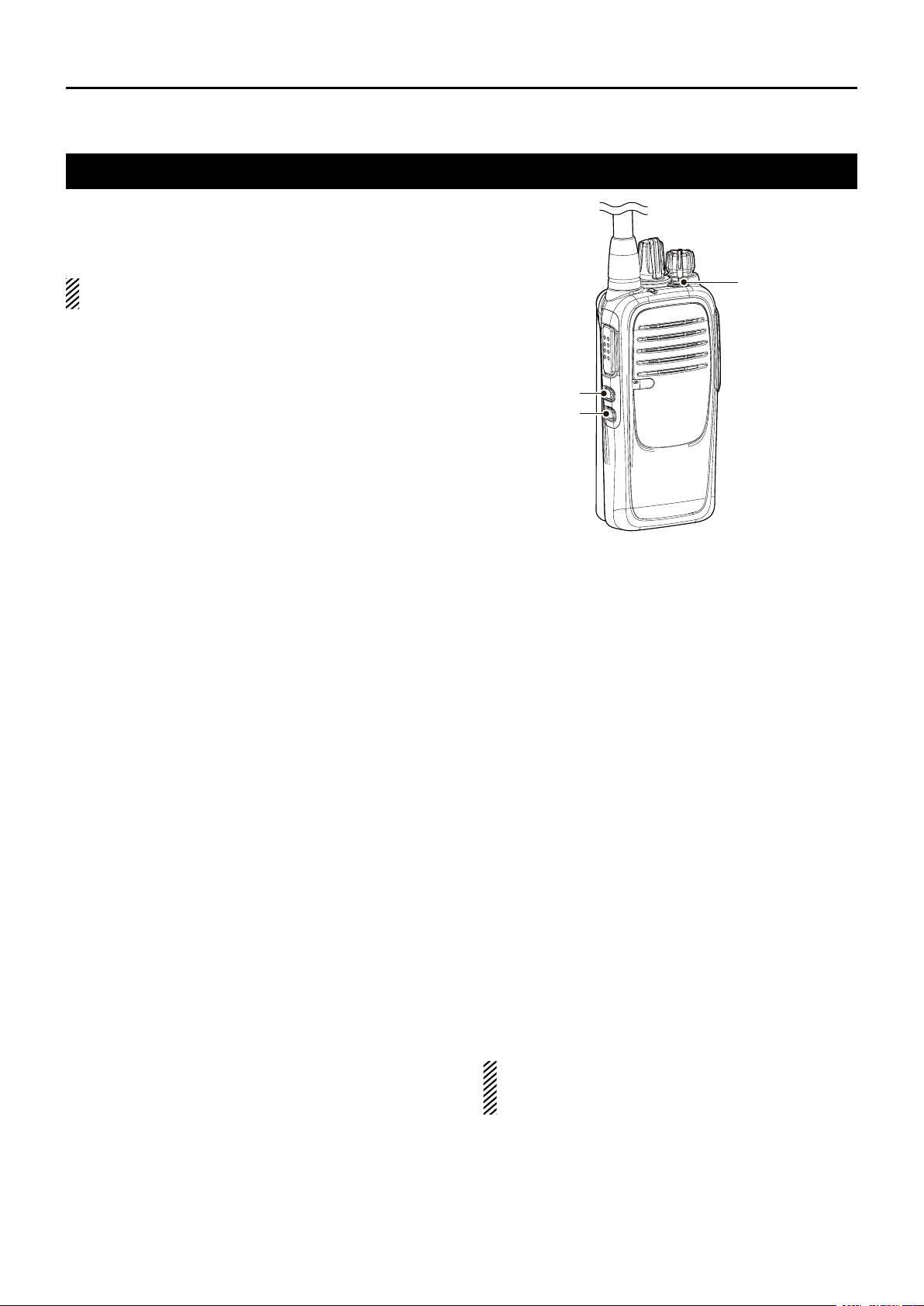
Programmable key functions
If you use the CS-F29SR c L O n i n g s O F t w a r e (purchase
separately), you can assign the functions described be-
low to [TOP], [Upper], and [Lower].
NOTE: Refer to the instruction sheet that comes with
the transceiver for the default settings of these keys.
SCAN START/STOP
Push to start and cancel a scan.➥
•WhenascanisstartedwiththePowerONScanorAuto-
matic scan function, push this key to pause it. The paused
scan resumes after a set time period.
PRIORITY A CHANNEL,
PRIORITY B CHANNEL
Push to select the Priority A or Priority B channel.➥
PRIORITY A
CHANNEL (REWRITE),
PRIORITY B
CHANNEL (REWRITE)
Push to select the Priority A or Priority B channel.➥
Hold down to set the operating channel as the Prior-➥
ity A or Priority B channel.
MEMORY CHANNELS 1, 2, 3, 4
Push to select memory channel 1, 2, 3, or 4.➥
MONI
Push to turn the CTCSS (DTCS) mute ON or OFF.➥
While holding down this key, the transceiver opens➥
any squelch, or releases any mute.
LOCK
Hold down to turn the Key Lock function ON or OFF.➥
•EvenwhentheLockfunctionisON,[MONI] and [SUR-
VEILLANCE] are not locked.
SURVEILLANCE
Hold down to turn ON the Surveillance function.➥
Push to turn OFF the function.➥
•WhenthisfunctionisONandasignalisreceived,abeep
does not sound and the status indicator does not light,
even if you push any key.
SIREN
Hold down to emit a siren sound.➥
•Thetransceiverkeepsemittingthesirensounduntilthe
transceiver’s power is turned OFF.
•Thisfunctionis forsituations otherthan an emergency
alert, such as a security alarm.
SCRAMBLER
Hold down to turn ON the Voice Scrambler function.➥
Push to turn OFF the function.➥
COMPANDER
Hold down to turn ON the Compander function.➥
Push to turn OFF the function.➥
•The Compander function reduces noise components
from the transmitted audio to provide clear communica-
tion.
S-RING/C-RING
Push to make a Smart-Ring call.➥
Hold down to make a Call-Ring call.➥
ANNOUNCE
Push to turn the Channel Announce function ON or➥
OFF.
•Thetransceiverannouncesthepositionof[RotarySelec-
tor].
NOTE: When the Beep function is OFF, the operat-
ing channel is not announced, regardless of this set-
ting. (p. 5)
[TOP]
[Lower]
[Upper]