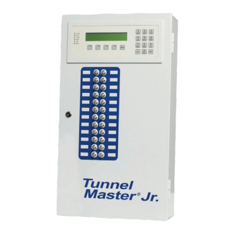
ICS Tunnel Master Jr User manual

TUNNEL MASTER JR MANUAL
Welcome 1
Welcome
Welcome, and thank you for purchasing your new Tunnel Master Jr. Car Wash Controller
from Innovative Control Systems, Inc.
As an ICS customer you benefit from a thoroughly researched car wash controller system.
This manual, “ICS Car Wash Controller System” has many features, which will enable you,
the operator, to have an active part in the control and operation of your car wash facility.
Controller Features:
•24 programmable, fused outputs, upgradeable to 48, each with two independent circuits
for 24vac and 110vac
•Programmable relay flashing feature
•Exclusive, patented anti theft feature to prevent unauthorized processing of car washes
•Input for Pulse, Gate, Tire, Roller Locator, Entrance Management and Panic circuits
•Auto pulse feature allows pulse simulation in the event of pulse switch failure
•Auto Gate feature allows gate switch simulation in the event of gate switch failure
•Exterior indicators for easy troubleshooting
•16 programmable service buttons on the entry keypad, upgradeable to 32
•Automated wet down feature for easy startup
•Optional report and/or receipt printers
ICS developed this manual in order to:
•Provide a comprehensive, easy-to-use system reference guide.
•Enable operators and their employees to obtain the maximum value from the system.
•Furnish operators with a tool for training their employees on the OEM Car Wash
Controller.
By reading the information and performing the procedures in this manual you should
be able to:
•Install your Tunnel Master Jr. Controller
•Configure your wash settings and features
•Process vehicles through your wash
•View car counts
•View historical information
•Track sales
•Print reports
•Troubleshoot problems if they occur
Many of the features you will find in the ICS Controller system were integrated at the
request of current car wash operators. We welcome your feedback and want to assure you
that ICS will always remain the best in the industry in car wash controller and management
systems.
Information in this manual is subject to change without notice. Companies, names and data used in examples within the manual are
fictitious unless otherwise noted. No part of this manual may be reproduced or transmitted in any form or by any means, electronic or
mechanical, for any purpose without the express written permission of Innovative Control Systems, Inc.

TUNNEL MASTER JR MANUAL
Table of Contents 2
Table of Contents
Chapter Title Page
1 System Hardware and Installation
Relay Box
Mounting and Installation
Pulse / Proximity Switch Wiring
Gate (Electric Eye) Switch Wiring
Tire Switch Wiring
Entrance Management System Wiring
Roller Locator Wiring
Panic Stop Circuit Wiring
Anti Collision Wiring
Input Wiring Summary
Relay Box Jumper Settings
Relay Box Dip Switch Settings
Entrance Keypad
Mounting and Installation
Entrance Keypad Jumper Settings
Entrance Keypad Dip Switch Settings
Report / Receipt Printer
Mounting and Installation
4
5
7
9
10
11
12
13
14
16
17
19
23
24
25
26
2 Configuring the Wash
The Relay Box Keypad
Accessing a Password Protected Menu
Configure Wash Menu
Setting Date Time
Set Password
Wash Settings
Outputs
Services
Output Lists
28
29
31
32
33
34
35
41
46
50
3 Operating Procedures
Main Wash Menu
Wet Down Wash
Processing Vehicles
Viewing Service Counts
Shift Break
53
54
55
56
59
61

TUNNEL MASTER JR MANUAL
Table of Contents 3
Printing Reports 62
4 Troubleshooting 66
Appendix
A Equipment Layout & Addressing Drawings
1 Relay Box, 1 Entry Keypad, Report &
Receipt Printer
2 Relay Boxes, 1 Entry Keypad, Report /
Receipt Printer
2 Relay Boxes, 2 Entry Keypads, Receipt &
Report Printer
72
73
74
Index 75

TUNNEL MASTER JR MANUAL
System Hardware 4
Chapter 1
System Hardware and Installation
Overview
Introduction This chapter provides a brief description of the hardware components
and their function. The Tunnel Master Jr. hardware is designed to
withstand the harsh environments and hard use of a busy car wash.
Both the Relay Box and the Input Station Keypad come with a 3-year,
conditional warranty, against defects in material, workmanship and
operating failure from normal use.
In this chapter This chapter covers the following topics:
Topic See Page
The Relay Box 5
The Entrance Keypad 17
The Report / Receipt Printer (Optional) 25

TUNNEL MASTER JR MANUAL
System Hardware 5
The Relay Box
Introduction The Relay Box is the control center for “firing” the various outputs or
services in the wash tunnel, i.e., Soap foamer, Reclaim motor, etc. The
Tunnel Master Jr. Controller relay box provides for automatic, computer
controlled or manual firing of the outputs. The relay box can control up
to 24 outputs.
Exterior
picture
24 toggle
switches Each switch controls the operation of one output or service. The switch
has three positions:
•UP = Manual Override- Will manually turn on output. (This feature
can be “turned off” if desired)
•MIDDLE = Output Off. The output will not “fire.”
•DOWN = Computer controlled on position (normal)-Computer turns
on output

TUNNEL MASTER JR MANUAL
System Hardware 6
The Relay Box
Interior picture Each relay has circuits to control both 24VAC and/or 110VAC
simultaneously so that a service sign as well as the service solenoid can be
operated from the same relay.
•Plug in relays for ease of serviceability
•Each relay has 2 fuses
•Built in spare fuses and fuse tester at the center bottom of the box
•Each relay can be programmed to “Flash” thus eliminating the need for
field installed flashing relays for signs.
Plug in relays for ease of serviceability
Each relay has two fuses (24VAC & 110VAC)
Built in spare fuses and fuse tester at the center
bottom of the box
24vac Transformer is for power
to the OEM circuit board ONLY.
Do not power any other devices
from this transformer!
Com Wire contacts for Entrance
Keypad, and Optional Report
Printer
Termination points for Pulse, Gate, Tire and Panic
circuits

TUNNEL MASTER JR MANUAL
System Hardware 7
The Relay Box Installation
Mounting and
Installation The following instructions will provide detail information on proper
mounting and installation of the Entrance Keypad (See Appendix A for
equipment layout. options.)
Relay Box Mounting
•All site wiring must be performed be a licensed electrician that must comply with all
local and national codes.
•The relay box must be securely mounted to the wall in the equipment room of the car
wash. The relay box is designed to be located in a dry, non-corrosive environment.
•The relay box must be located so that conduit connections can be easily made, and the
relays can be readily accessed.
Relay Box Wiring
•Install one approved 3/4” conduit from the Relay Box to the Entrance Keypad box
located near the front of the wash tunnel. All conduit runs should meet all local and
national codes. Conduits shall be properly connected and securely fastened to the boxes
with Listed conduit hubs, and should be tightened to the torque specs of the
manufacturer. Over torqueing may cause enclosure breakage.
•Electrician must provide a dedicated 110vac circuit to power the Relay Box
•Run a 14-3 cable to the 110vac terminal block. It is labeled with H and N for Hot and
Neutral, respectfully. There is a mechanical ground lug located on the back of the box
adjacent to the terminal block. It is labeled with the universal ground symbol.
Terminations for the shielded cable should be torqued to 35 pound-inches.
•Electrician must supply a separate 24vac and 120vac circuit to the common (C) side of
the upper and lower termination points of each relay respectively, then loop the
commons together to each relay. This power is to “fire” the solenoids and equipment.
•A separation of 110vac and 24vac shall be maintained for all field-wiring circuits. All
24vac circuits must be supplied by a class 2 transformer.
•Tighten all wires on the circuit board in the relay box to 20 pound-inches (2.3 n-m.)
Overtorquing may cause enclosure breakage.
•Relays in the relay box are double pole with independent commons so that each relay
can have two circuits running through it. Commons are independent to provide a power
source to switch two devices through either the normally open or normally closed
circuits.
•Relays circuits should be supplied with no greater than 120vac 15amp.
This 120vac MUST BE A SEPARATE circuit from the dedicated 110vac circuit
terminated in the lower right corner of the OEM Relay Box.

TUNNEL MASTER JR MANUAL
System Hardware 8
The Relay Box Installation
Relay Box Wiring
•A 6.3 amp 250v fuse protects each relay. Four spare fuses along with LED fuse test
indicators are located at the bottom of the relay board. (Fuses should not be replaced
with any other device.)
•Another approved, ¾” conduit needs to be run to your motor control center to the Relay
Box and will contain the low voltage wires for clock (Pulse), gate (Entrance switch) and
Tire switch functions.
•When using a normally open 2-wire pulse switch, use terminals marked CLK SINK and
PROX GND. (See Pulse switch wiring diagrams)
•When using a normally open 3-wire pulse switch, use terminals marked PROX PWR,
CLK SINK, and PROX GND. (See Pulse switch wiring diagrams)
•Gate inputs and Tire inputs require a constant 24vac neutral supplied from a class 2
transformer. The hot signal would be terminated to the normally open pole of the
electric eye (gate) switch. (See wiring diagrams for Gate Switch and Tire Switch)
•Panic circuit inputs requires a constant 24vac neutral supplied through the stop/start
circuit. (See wiring diagrams for Panic Circuit options)

TUNNEL MASTER JR MANUAL
System Hardware 9
Pulse/Proximity Switch Wiring
Pulse Switch
Wire Diagram The following diagram shows how to wire the pulse / proximity switch
into the Relay Box.
Important! The pulse switch is a critical input for the OEM Controller. It signals
the system that the conveyor is moving and is the measuring device
from which the system knows when to turn equipment devices on and
off. See wash equipment vendor for location of the switch.
The OEM Controller is designed to accept all commonly used
pulse/proximity switches. There are two types that are most commonly
used, either a two wire or three wire "Sinking" (NPN) switch. The
drawing below indicates the wiring for these two types of switches.
The other type of switch is defined as a "Sourcing."(PNP) If it is
determined that this type of proximity switch is being used there are
two jumpers located just below the "CLK SINK" and "CLK SRCE"
contacts (JP1) & (JP2). These jumpers must be moved to the SOURCE
jumper position. Some pulse switches vary in the wire color. You
should check the pulse / proximity switch manual for proper color
codes.
Smart Relay Box
2-Wire Pulse Switch with
Normally Open Contact 3-Wire Proximity Switch
Sinking (NPN)
N.O. Com GND +12V SIGNAL
Relay Box
Used when connecting standard “Push Button” entry box

TUNNEL MASTER JR MANUAL
System Hardware 10
Gate (Electric Eye) Switch Wiring
Gate Switch
Wire Diagram The following diagram shows how to wire the Gate (electric eye)
switch into the Relay Box.
Important! The "Gate" switch is the second critical input device to the OEM Relay
Box. It is usually an electric eye system or some type of vehicle
position detector located just before the first piece of wash equipment.
This switch signals the OEM Controller that a vehicle is starting
through the tunnel. All equipment turn on points are measured from
this switch to the particular piece of equipment.
This diagram to the Smart Relay Box starts at the control relay for the
sensing device being used. See the wash equipment provider for
location of this relay.
Used when connecting s
tandard
“
Push Button
”
Box
OEM Relay Box
Gate
-
Gate
+
24vac Power Source
(Supplied by Other)
NeutralHot
Electric Eye or Other
Sensing Device Relay
N.O.Common
Smart Relay Box
Relay Box

TUNNEL MASTER JR MANUAL
System Hardware 11
Tire Switch Wiring
Tire Switch
Wire Diagram The following diagram shows how to wire the Tire switch into the
Relay Box.
Important! This circuit is used if the customer has purchased a tire position switch
from the equipment vendor. The switch enables the Controller
software to turn equipment on and off as each of the vehicle's tires pass
that piece of equipment. In order for this to work properly, the tire
switch should be located in line with the gate switch.
Tire - Tire +
24vac Power Source
(Supplied by Other)
NeutralHot
N.O.Common
Smart Relay Box
Relay Box

TUNNEL MASTER JR MANUAL
System Hardware 12
Entrance Management System Wiring
EMS Treadle
Wiring Diagram The following diagram shows how to wire the treadle switch for the
EMS into the Relay Box.
Important Note: This circuit is used if the customer has purchased a treadle switch from
the equipment vendor. The Entrance Management System in the
Tunnel Master Junior allows a roller to be fired automatically upon
seeing a second 24Volt input on Input 10. At the same time, an output
can be set to fire and the roller can be delayed.
When a car enters the tunnel the TMJ will wait to see two signals
within 15 seconds of each other from the tire treadle that is wired into
Input 10. The first signal represents the front tire and the second signal
represents the rear. Once it sees the second signal, the TMJ will fire an
optional sign relay followed by a roller relay. The amount of time
between the sign firing and the roller is called the “Entrance
Management Delay” in the Wash Settings.

TUNNEL MASTER JR MANUAL
System Hardware 13
Roller Locator Wiring
Roller Locator
Wire Diagram The following diagram shows how to wire the Roller Locator into the
Relay Box.
Important Note: You can add a roller locator to the TMJ to keep your rollers from
jamming your conveyor. In order to do this a roller locator switch must
be installed in on your conveyor to signal the presence of a roller.
When a roller locator is used, the TMJ will wait to fire a roller until the
trailing edge of the signal is detected from a roller locator. There are
various devices available to detect the roller and because the TMJ reads
the trailing edge of the signal either a normally open or normally closed
switch can be used.
To set this up two things need to be done.
1. A roller locator switch needs to be wired into input 9, and
installed on the conveyor. This switch should be positioned so
that as soon as a roller passes the switch it will be in a position
where it is safe for the roller forks to come up.
2. Turn the roller locator function on in Wash Settings

TUNNEL MASTER JR MANUAL
System Hardware 14
Panic Stop Circuit Wiring
Panic Stop
Circuit Diagram The following diagram shows how to wire the Panic Stop circuit into
the Controller.
Important! This drawing shows the basic wiring of the panic circuit. The Panic
circuit allows for certain software programming that could not be
programmed without this circuit in place.
See Diagram on Next Page

TUNNEL MASTER JR MANUAL
System Hardware 15

TUNNEL MASTER JR MANUAL
System Hardware 16
Anti Collision
Anti Collision Wiring
Diagram The following diagram shows how to wire an anti collision
system into the Tunnel Master Jr.
Important! The anti-collision on the Tunnel Master Jr. is a function to
help prevent cars from running into each other at the exit
end of the tunnel. In order for this to work you need an anti-
collision device mounted in the tunnel at the spot where you
could have a potential collision.
The process consists of two variables in order for the
Tunnel Master Jr. to go into an anti-collision panic. The first
variable is for the Jr. to see a car through some sort of
sensing device. The second variable is the Anti-collision
start time in wash settings on the Jr. When a car is in the
sensing device and a second car reaches the Anti-collision
start time, the system will go into a panic until the sensing
device is cleared. The system must also have a panic circuit
wired in for this function to be able to restart the conveyor.
(See the TMJ conveyor enable circuit drawing )

TUNNEL MASTER JR MANUAL
System Hardware 17
Tunnel Master Junior Input Wiring Summary
Input Wiring
Summary The following diagram shows where all of the TMJ inputs get wired
into.

TUNNEL MASTER JR MANUAL
System Hardware 18
The Relay Box Jumper Settings
Jumper Settings The following picture and table will explain the location and
purpose of the various jumpers on the Relay Box circuit board.
The following picture shows the Relay Box door circuit board and
location of the various jumpers, switches and controls.
Relay Box Circuit
Board
Jumper Function These are the jumper functions and their settings
Jumper Setting Function
J1 N/A
Does not exist
J2 ON
BIAS High (+) set ON for the Main Relay box only.
J3 485
3 position jumper should be on 2 pins to select 485 Communication
(UP)
J4 485
3 position jumper should be on 2 pins to select 485 Communication
(UP)
J5 ON
Transmit terminating resister. Only ON if first or last device in
network.
If you have a 24-output system this should be ON. IF you have a
48-output system, the main relay box should be OFF and the second
relay box should be ON.
JP4 JP10
JP6
JP7
JP5
JP2
JP3
JP8
JP9 JP11
Dip Switch
Contrast Control
for front of box
LED display
(SW1) Circuit
Board Reset
Button

TUNNEL MASTER JR MANUAL
System Hardware 19
J6 485
3 position jumper should be on 2 pins to select 485 Communication
(Left)
J7 OFF
Receive terminating resister.
J8 ON
Network Interface Chassis Ground Jumper
J9 ON
Network Interface Signal Ground Jumper
J10 ON
BIAS Low (-) set ON for the Main Relay box only.
J11 ON
ON = Enables, OFF = Disables manual override switches on relay
box,

TUNNEL MASTER JR MANUAL
System Hardware 20
The Relay Box Dip Switch Settings
Dip Switch Settings The following picture and table will show the Relay Box Dip
switch and the various settings that may be used.
Helpful Tips ☺For location of the Dipswitch refer to the previous Relay Box
picture on page 14. The “ON” position is always up. A 24 Output
Relay Box will ship as ADDR1. If you were to add a second
Relay Box to the system, it should be addressed as ADDR9.
The following picture shows the Relay Box door Dip switch.
Relay Box Dip
Switch
Switch Normal
Setting/Function These are the dipswitch settings for normal operations.
Switch Setting Function
1 OFF Address setting:
2 OFF Address setting
3 OFF Address setting
4 OFF Address Setting
1, 2, 3, 4 OFF
1 ON, 2, 3, 4 OFF
1 ON, 2, 3 OFF, 4 ON
1 & 3 ON, 2 & 4 OFF
1 ON, 2 OFF, 3, 4 ON
= Address 1
= Address 9
= Address 10
= Address 11
= Address 12
5 OFF Baud Rate: OFF = 9600 ON = 38,400
6 OFF Up position allows access to Initialization Menu options
7 OFF Pulse Enhancement
8 OFF Pulse Enhancement
7 & 8 OFF
7 OFF, 8 ON
7 ON, 8 OFF
7 & 8 ON
Normal
2 Times
4 Times
8 Times
Other manuals for Tunnel Master Jr
2
Table of contents
Other ICS Controllers manuals
Popular Controllers manuals by other brands

Oldham
Oldham MX 32 Installation and operating manual

krispol
krispol STARCUS SCENARIO operating instructions

Homematic IP
Homematic IP HmIP-RGBW Installation and operating manual

Danfoss
Danfoss Icon Master installation guide

Haier
Haier YCZ-A001 Installation and operating instruction

Hypex Electronics
Hypex Electronics PSC2.400 user manual