ADS-RR(SR)-HK2-DS-IG-EN maestro.idatalink.com
Hyundai Elantra witH naV witH aMP 2014-2016
Automotive Data Solutions Inc. © 2021 3
INSTALLATION INSTRUCTIONS
STEP 1
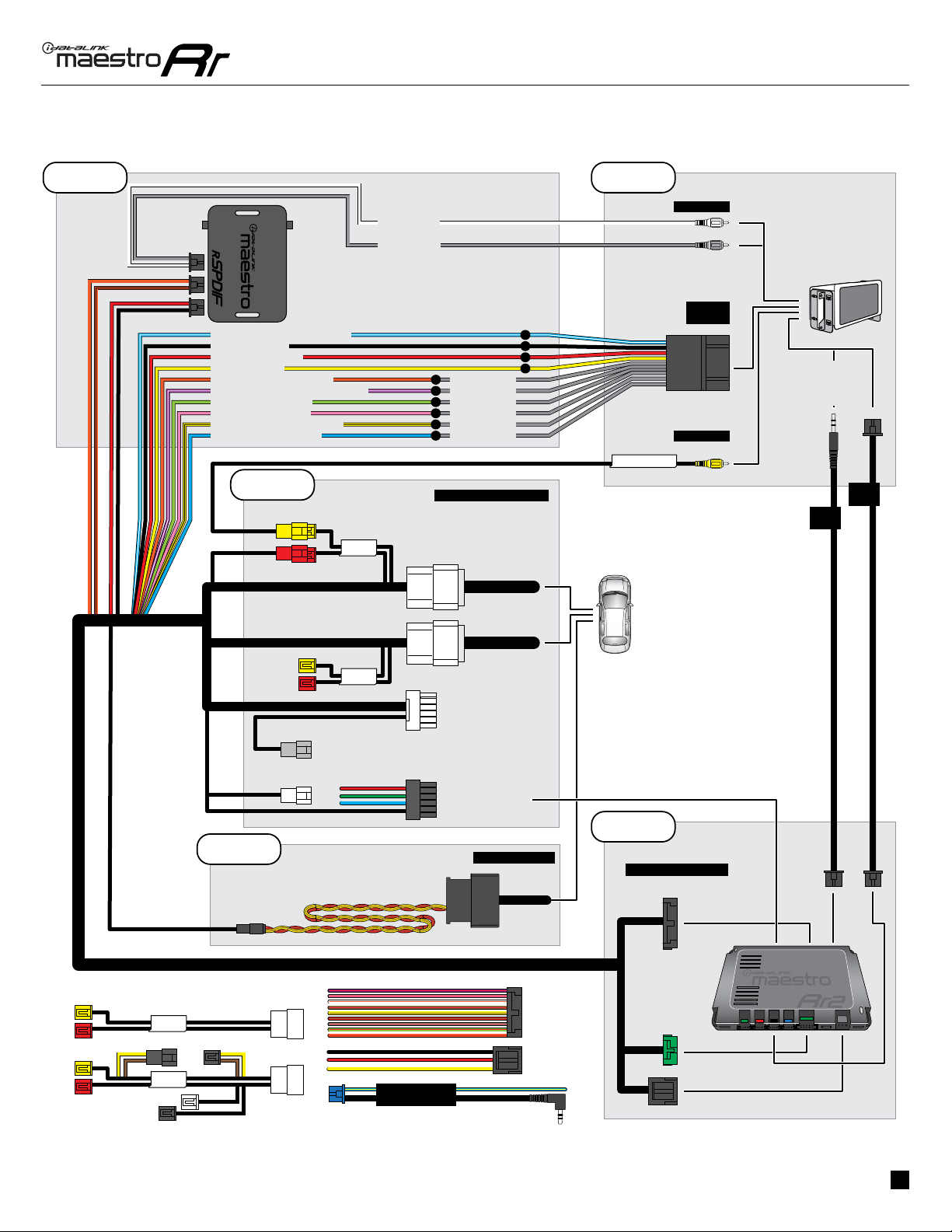
• Unbox the aftermarket radio and locate its main harness.
• Connect the wires shown on the next page from
aftermarket radio main harness to the rHK2 T-harness and
match the wire functions.
• Connect the rHK2 T-harness and the RCA cables to the
rSPDIF1.
There are two switches on the rSPDIF that need to be set
properly: Bit Rate and Input Level:
• Bit Rate: Set switch to 48 kHz.
• Input Level: If the radio you are installing has a rca preout
voltage of 3 volts or less (Look in the radios owners manual
for this specification) set the Input Level to “Low”. If the
radio has a rca preout voltage of 4 volts or more then select
“High”.
Note: Isolate (tape) unused wires, if applicable.
STEP 2
• Remove the factory radio.
• Assemble the rHK2 T-harness as shown in wiring diagram
(If there is an OEM camera, connect the backup cam rca
cable to the rHK2 T-harness, as shown).
• Connect the factory radio harness to the rHK2 T-harness.
STEP 3
• Plug the male BLACK 2 pin connector of the rHK2
T-harness into the OBDII harness.
• Plug the OBDII connector into the OBDII of the vehicle,
located under the driver side dash.
STEP 4
• Plug the aftermarket radio harnesses into the aftermarket
radio.
• Connect the RCA cables in the front RCA outputs of the
radio.
• Plug the backup camera RCA into the aftermarket radio’s
backup camera input (if applicable).
• Plug the Data cable to the data port of the aftermarket
radio.
• Insert the Audio cable into the iDatalink 3.5 mm audio jack
of the aftermarket radio (If there is no iDatalink audio input,
connect to AUX).
Note: On Pioneer radio, ensure that there is nothing
plugged into the W/R port.
STEP 5
• Connect all the harnesses to the Maestro RR2 module
then test your installation.
1