Fnirsi FNB48 User manual
1
FNB48 User Manual
(V0.6)

2
Catalog
0.0 Versions and Updates............................................................................................................................4
1.0 Overview................................................................................................................................................... 4
2.0
Safety Precautions.................................................................................................................................. 4
3.0
Performance description......................................................................................................................5
3.0.1 Interface................................................................................................................................................... 5
3.0.2 Human-computer interaction............................................................................................................5
3.0.3 Voltage and Current............................................................................................................................. 5
3.0.4 Fast charge trigger................................................................................................................................ 5
3.0.5 Wire identification class.......................................................................................................................6
3.0.5 Miscellaneous........................................................................................................................................6
4.0 Structure appearance............................................................................................................................ 7
5.0 Technical index...................................................................................................................................... 10
6.0
Main page................................................................................................................................................11
6.0.1 Concise page........................................................................................................................................ 11
6.0.2 Record page..........................................................................................................................................12
6.0.7 Fast charge recognition page.......................................................................................................... 13
6.0.8 Curve display page............................................................................................................................. 14
6.0.9 Wire resistance measurement page...............................................................................................15
7.0
Record function expansion...............................................................................................................16
7.0.1 Energy statistics list.............................................................................................................................16
7.0.2 Battery capacity calculation tool.....................................................................................................17

3
8.0
Quick charge protocol trigger and detectionmenu.................................................................18
8.0.1 Fast charge protocol automatic detection...................................................................................19
8.0.2 QC2.0 Trigger........................................................................................................................................ 19
8.0.3 QC3.0 Trigger........................................................................................................................................ 20
8.0.4 Huawei FCP trigger............................................................................................................................20
8.0.5 Huawei SCP trigger............................................................................................................................. 20
8.0.6 Samsung AFC trigger......................................................................................................................... 20
8.0.7 PD Protocol trigger............................................................................................................................. 21
8.0.8 PD Protocol conversion......................................................................................................................21
8.0.9 VOOC/WARP Constant voltage trigger...........................................................................................22
8.0.9 SVOOC Trigger..................................................................................................................................... 22
9.0
Charging tool......................................................................................................................................... 23
9.0.1 PD Listener.............................................................................................................................................23
9.0.2 Read E-Marker cable.......................................................................................................................... 25
9.0.3 Read DASH cable................................................................................................................................ 26
9.0.4 Analog DASH cable............................................................................................................................ 26
9.0.5 Apple 2.4A acceleration.....................................................................................................................26
10.0
Setting menu........................................................................................................................................ 27
10.2
Settings menu -> Record...................................................................................................................27
10.3
Trigger related configuration........................................................................................................... 27
10.4
Settings menu -> system...................................................................................................................28
11.0 Upgrade firmware instructions..................................................................................................... 28

4
0.0 Versions and Updates
As instrument products have many functions and frequent software and
hardware updates, the manual may be updated at any time, please be aware.
Please get the latest update information on the official website.
1.0 Overview
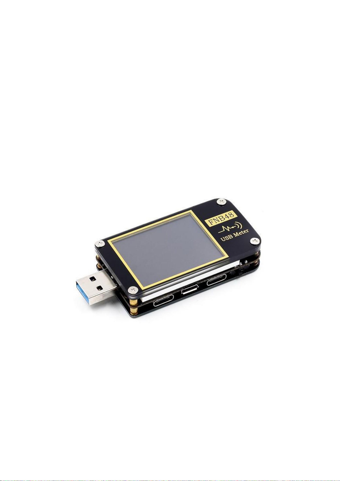
The FNB48USB tester is a high-reliability, high-safety USB voltage and
current detection meter and a mobile communication terminal fast charging
trigger. It has a 1.77-inch TFTLCD display and integrated USB-A, Micro-USB,
Type-C interfaces. Use external 16-bit ADC, PD protocol physical chip. It
can be used to measure the power supply or power consumption of products
such as USB interfaces, mobile phone chargers, U disks, etc.; it can be used
to measure mobile phone charging power and mobile power input and output
conditions; it can be used for charger fast charging protocol testing.
This instruction manual includes relevant safety information, warning
tips and solutions to common abnormal situations. Please read the relevant
content carefully and strictly abide by all warnings and precautions.
2.0
Safety Precautions
1 Do not connect the monitoring interface to a power supply exceeding 24V;
2 Do not connect the PC connection port to a power source exceeding 16V;
3 Only one pair of monitoring interfaces (one input port, one output
port) can work at the same time. When there is a pair of monitoring
interfaces working, it is forbidden to connect to the equipment on
other monitoring interfaces. (Except the PC connection port, the PC
port can be connected to an external power supply)
4 When using the fast charge trigger module, please do not connect
equipment that cannot withstand high voltage to any monitoring interface;
5 After using the PD trigger/monitor/conversion/read E-Marker cable
function, please turn the PD communication switch in the lower right
corner back to the OFF position;
6 When working at high power,The temperature of the instrument rises,Please
be careful,Prevent burns
7 Do not charge the phone after the fast charge is triggered,Therefore,
the phone is damaged, The manufacturer is not responsible.

5
3.0
Performance description
3.0.1 Interface
1Input monitoring port: USB-A, 9-PIN male;
2Input monitoring port: TYPE-C, 24-PIN female seat;
3 Input monitoring port: Micro-USB, 5-PIN female socket; 4 output
monitoring ports: USB-A, 9-PIN female socket;
5Output monitoring port: TYPE-C, 24-PIN female socket;
6 PC connection port: Micro-USB, 5-PIN female socket.
3.0.2 Human-computer interaction
11.77 inch TFT-LCD screen;
2Multi-function switch;
3Touch switch.
3.0.3 Voltage and Current
1The highest six-digit display of voltage, current and power, the highest
resolution is 0.00001 (V/A/W);
2Record the minimum, maximum and average values of voltage, current,
and power during operation;
210 sets of switchable capacity, power, and time statistics;
31 set of voltage and current curve records, maximum support 9 hours
4Support low-speed waveform (voltage, current, D+, D-) drawing, 2sps-
>100sps sampling rate;
5Support high-speed ripple (voltage, AC coupling) drawing, up to 3.2Msps
sampling rate;
3.0.4 Fast charge trigger
1 QC2.0,QC3.0 trigger;
2Huawei FCP,SCP trigger;
3Samsung AFC trigger;

6
4PD2.0/3.0 Trigger;
5VOOC/WARP Trigger;
6SuperVOOC Trigger;
7The above protocols all support automatic monitoring
8MTK-PE automatic detection;
9Support QC2.0->PD2.0 protocol conversion;
10 Support a maximum of 24 hours for a limited time trigger, and
automatically close the trigger when the time comes
3.0.5 Wire identification class
1
The internal resistance measurement of the wire by the differential pressure method;
2
E-Marker Cable chip reading;
3
DASH Cable data reading;
3.0.5 Miscellaneous
1 Record of startup time;
2 Onboard temperature measurement;
3 Gravity sensor, automatically switch the display direction;
4 PD monitor;
5 Analog DASH cable;
6 Apple 2.4A acceleration;
7
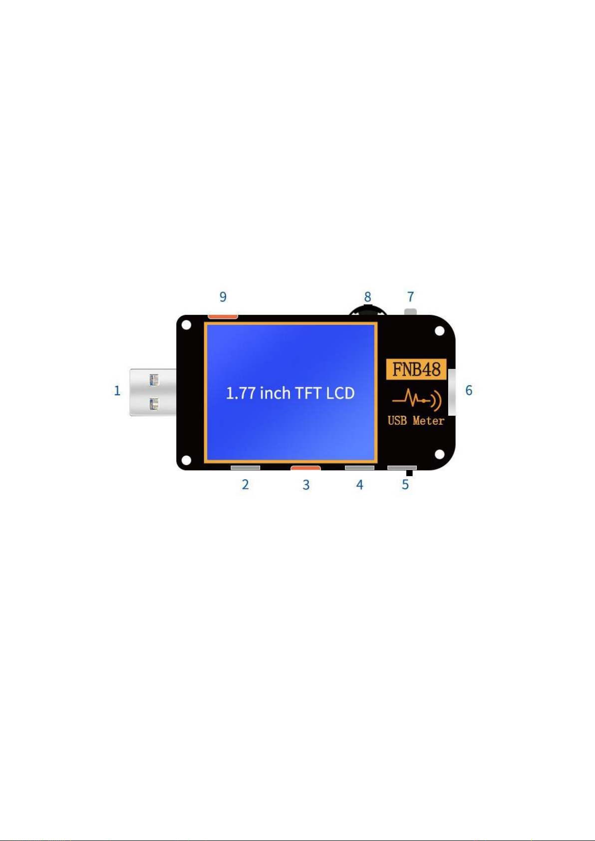
4.0 Structure appearance
1 Input monitoring port: USB-A, 9-PIN male;
2 Input monitoring port: TYPE-C, 24-PIN female socket;
3 input monitoring port: Micro-USB, 5-PIN female
socket; 4 output monitoring port: TYPE-C, 24-PIN
female socket; 5 PD communication switch
6 output monitoring port: USB-A, 9-PIN
female; 7 touch switch: BACK button;
8 Multi-function switches: left button, middle button, right
button; 9 PC connection port: Micro-USB, 5-PIN female socket..

10
5.0 Technical index
Accuracy: ±(a%(‰) reading + number of words)
Index
Range
Resolution
Accuracy
Monitor voltage
4~24V
0.00001V
±(0.2‰+2)
Monitor current
0~6.5A
0.00001A
±(0.5‰+2)
Monitor power
0~156W
0.00001W
±(0.5‰+2)
Load equivalent
internal
resistance
0~9999.9Ω
0.0001Ω
±(0.5‰+2)
D+/D- voltage
0~3.3V
0.001V
±(1.0%+2)
Equipment
temperature
℃
1℃
±(1.2%+3)
℉
1℉
±(1.2%+4)
Capacity
0~9999.99Ah
0.00001Ah
Energy used
0~9999.99Wh
0.00001Wh
Cable resistance
0~9999.9Ω
0.0001Ω
Equipmnt running
time
99 days 23 hours 59
minutes 59 seconds
1 second
Record time
999 hours 59 minutes
59 seconds
1 second
11
6.0
Main page
Except for special instructions, the left and right buttons switch
pages/menus, the middle button confirms, and the BACK button
cancels/returns.Long press the BACK button to turn off the screen
backlight, all pages are valid.
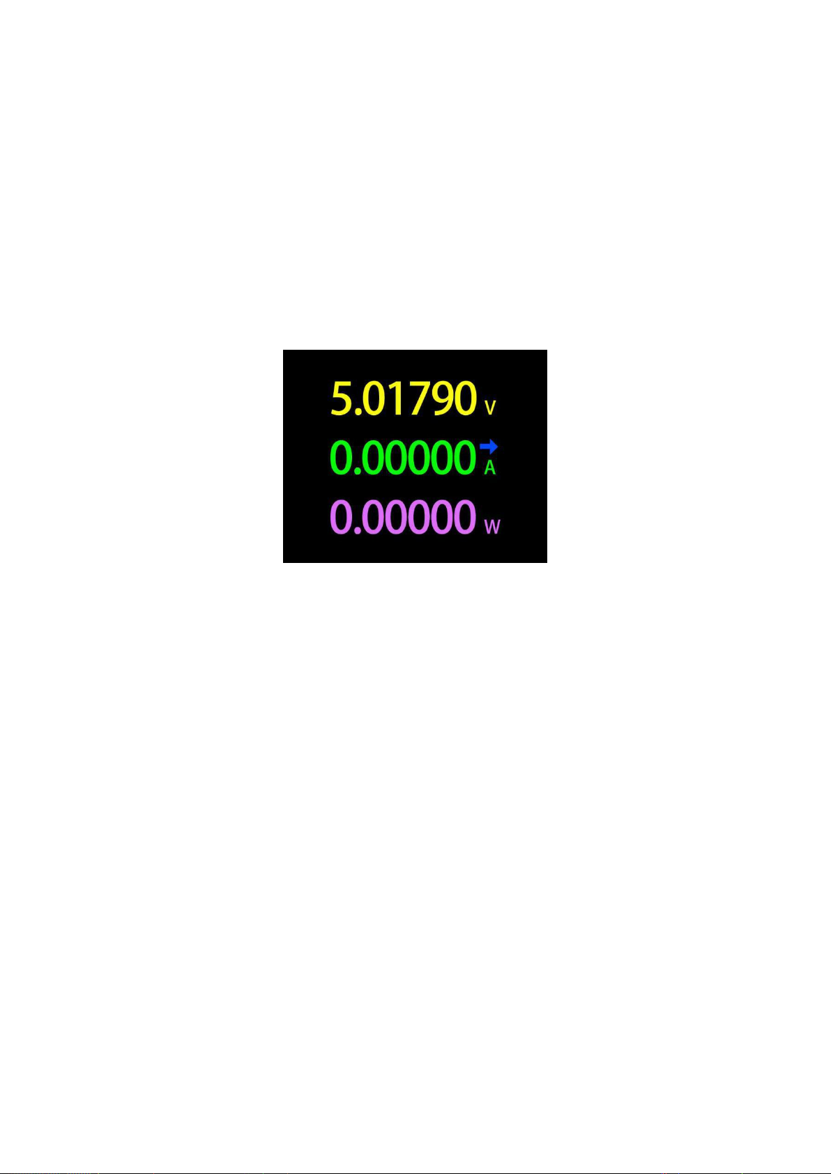
6.0.1 Concise page
Description
Only the three key parameters of voltage, current and power are displayed,
→ indicates the direction of current. This page can change the
display direction.
Instructions
(1) Long press the left button: enter the setting menu.
(2) Click the middle button: switch to 6-bit resolution.
(3) Long press the middle button: When the setting
menu -> general -> gravity direction is recognized as
off, switch the screen direction.

6.0.2 Record page
Description
The top row of data from left to right are boot record time and onboard
temperature respectively;
The uppercase data on the left is voltage, current, and power from top to
bottom;
The curve and progress bar on the right are the remaining storage
capacity of the voltage and current curves;
The groups on the right are from top to bottom,statistics group,
current group capacity, power, time value;
Starting from the lower left corner, the Min, Max, and Avg data are the minimum,
maximum, and average values of voltage, current, and power respectively. Voltage,
current, and power can be distinguished according to the unit;
There are two text boxes in the lower right corner, the first 1.0 from top
to bottom is the setting menu -> recording -> offline recording time, in
hours, it is highlighted when recording, otherwise it is grayed out; the
second is the setting menu -> Record->Energy statistics time, unit hour,
when the value is 0.0, it means there is no time limit for statistics.
Instructions
(1)
Long press the left button: switch to the capacity/power consumption list (please see
the following instructions).
(2)
Click the middle button: start/stop the voltage and current curve recording, it cannot
be started when the recording time is 0.
(3)
Long press the middle button: restart the calculation of the minimum, maximum and
average values of voltage, current and power.
(4)
Long press the right button: enter the battery capacity calculation tool (please see the
subsequent instructions).
12

13
6.0.3 Fast charge recognition page
Description
The top row of data from left to right are boot record time and onboard
temperature respectively;
The uppercase data on the left is voltage, current, and power from top to
bottom; The trigger time limit on the right is the setting menu -> trigger
-> trigger time value.Trigger timing is the timing of trigger time,When the
timing reaches the trigger time limit,The meter will stop triggering. Note
that:After some protocols stop triggering, the charger will restart.
The dark blue below the trigger timing is the load resistance.
The first column of the bottom white table is D+, D- voltage;The second
column is the current charging agreement that may be in progress;The third
column is the status bar.
当触发计时为启动时,显示为
,停止时为 ;当仪表未触发任何快
充协议时为 ,已触发某种快充协议,如 QC2.0 时,为 .
Instructions
(1)
Long press the left button: prompt to enter the fast charge trigger module, if a certain protocol
has been triggered, it will prompt to release.
(2)
Click the middle button: start/stop the trigger timing.
(3)
Long press the middle button: prompt to clear the trigger timing.
(4)
Long press the right button: enter the charging tool menu (please see the subsequent
instructions).

14
6.0.4 Curve display page
Description
From left to right:
Mode 1: Low-speed voltage and current curve.
Mode 2: Low-speed D+D-
curve. Mode 3: Record
offline curve.
Mode 4: High-speed voltage ripple (AC coupling).
Instructions
(1)
Long press the left button: time base minus.
(2)
Click the middle button: start/pause drawing the curve. (Except in mode 3, it will prompt
whether to clear the curve).
(3)
Long press the middle button: switch modes.
(4)
Long press the right button: time base plus.

15
6.0.5 Wire resistance measurement page
Description
FNB48 uses the differential pressure method to measure the internal resistance of the
cable, which needs to be used with a constant current load.
(1)
Click the middle button: use the current voltage and current
value as the reference value
Measurement procedure
(1) Connection mode: charger + FNB48 + constant current load (the
current is adjusted to about 0.5-1A), and record the reference
value.
(2) Connection method: charger + cable + FNB48 + constant current
load (the current is adjusted to about 0.5-1A, which needs to be
similar to the current when the reference value is recorded),
the system automatically calculates the internal resistance of
the cable
16
7.0
Record function expansion
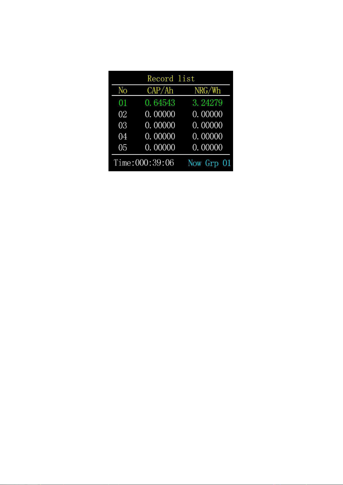
7.0.1 Energy statistics list
Description
In the record page (6.0.2), long press the left button to enter.
Each line in the list represents a group of parameters, from left to
right are group number, capacity, energy, the selected group is
displayed in green, and the lower left corner is the selected group
Statistics time, the lower right corner
is the group number of the current statistics group.
Instructions
(1)
Click the middle button: switch to the selection group.
(2)
Long press the middle button: select whether to clear the selected group.
17
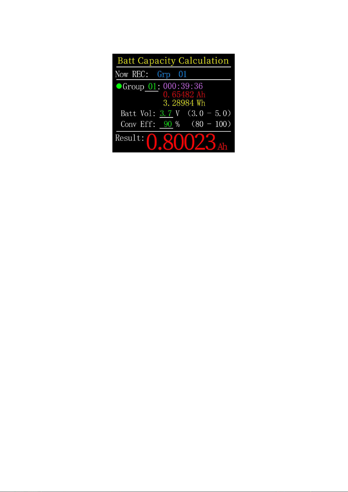
7.0.2 Battery capacity calculation tool
Description
In the record page (6.0.2), press and hold the right button to enter.
Select the statistics group,Set battery voltage, energy conversion
efficiency, The battery capacity can be calculated.Click the middle
button to move the green dot on the left between Group, BattVol and
ConvEff. Which item the green dot is in, you can change the value of
which item by clicking the left/right button.Each item is explained
below.
(1)Group is the statistical group selected for calculation. This
instrument can be selected from 1-10 groups, statistical time, capacity,
energy,It is displayed in order from top to bottom on the right of the
selected group number.
(2)BattVol is the battery voltage, the default is 3.7V, this parameter
can be selected from 3.0-5.0V, the actual value,Please check the relevant
information yourself.
(3)ConvEff is the energy conversion efficiency, the default is 90%.
(4)The red letter is the calculation result. If you want to get the
result in mAh, please convert it to x1000 by yourself.
18
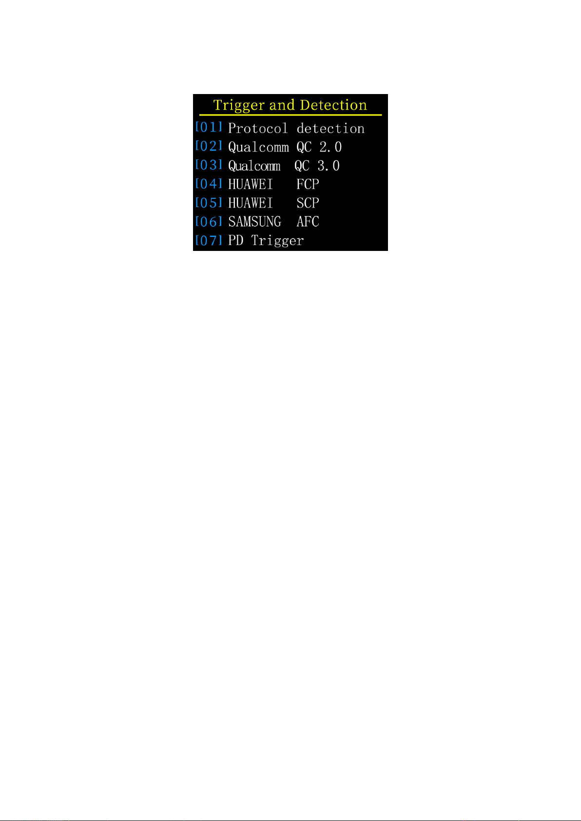
8.0
Quick charge protocol trigger and detection menu
Description
On the (6.0.3) fast charge recognition page, long press the left button
and confirm to enter..
This meter supports QC2.0/QC3.0, HuaWeiFCP/SCP, SamsungAFC trigger,
VOOC/DASH constant pressure mode, PD2.0/3.0 trigger, and QC2.0->PD2.0
protocol conversion
Note
Once you enter the quick charge trigger/detection
interface, All operations must be carried out carefully,
It is forbidden to access equipment that cannot withstand high voltage,
In the process of using this function,
The author shall not be liable for losses caused by misoperation.
19
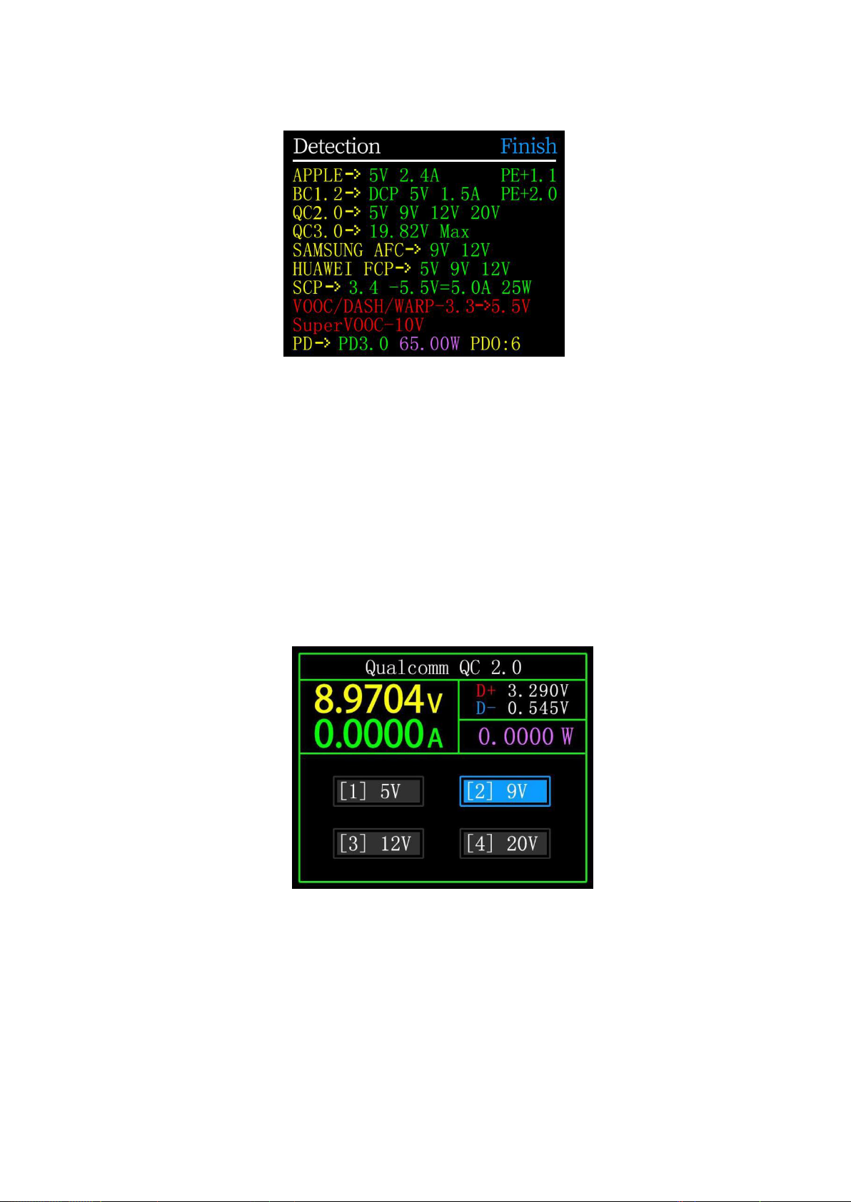
8.0.1 Fast charge protocol automatic detection
In this mode,The meter tries to trigger various protocols in
turn,Display the test results on the screen,Red is not supported,Green is
support,In the process of testing,Such as measuring PD chargers,It is
normal to restart and continue testing.During the test, it is forbidden to
connect to any equipment at the back end.
It does not respond to any key operation during the test. If you want
to exit during the test, please unplug the meter directly. After the test
is completed, click the middle button to start the test again; click the
BACK button to return to the previous page.
8.0.2 QC2.0 Trigger
In QC2.0 trigger mode, use the left and right keys to select the trigger
voltage, and click BACK to return.

20
8.0.3 QC3.0 Trigger
In QC3.0 trigger mode,Use the left and right keys to decrease/increase
the trigger voltage,Click BACK to return.Press the left/right keys to
quickly decrease/increase the voltage.
8.0.4 Huawei FCP trigger
The operation method is the same as QC2.0 trigger.
8.0.5 Huawei SCP trigger
The operation mode is the same as QC3.0 trigger
8.0.6 Samsung AFC trigger
The operation method is the same as QC2.0 trigger.

21
8.0.7 PD Protocol trigger
Switch the PD communication switch to ON, Enter the PD protocol trigger mode.
After exiting the PD trigger, switch the PD communication switch to OFF.
Take the picture as an example. The picture shows a message sent by a
charger.There are 6 gears in total, of which gears 1, 2, 3, 4, and 5 are fixed
voltage gears.The sixth gear is the adjustable voltage gear (PPS).
When the left dot stays on Gear,The gear can be switched by the left and
right keys. When the gear is switched to PPS gear,Then you can switch the
step voltage by clicking the middle button,After selecting the step voltage,
Through the left and right keys (left minus right plus),Decrease/increase
voltage.
8.0.8 PD Protocol conversion
This function is used for only QC2.0 charger,But want to supply power to PD
appliances.Before use,Switch the PD communication switch to ON,Then enter the PD
protocol conversion mode, after entering,Plug in PD appliances,You can perform
PD fast charge.
In this mode,Click the middle button and use the left and right buttons to
change the maximum power of packets sent by the PD.When changing power,Be
careful not to exceed the charger power to avoid unnecessary damage.After
changing the power, you must click the middle button to confirm.
Set 5V when no device is connected,Avoid high-voltage damage to mobile
phones that do not support high-voltage when plugged in.
QC2.0 only B type charger supports 20V trigger,So when the PD appliance
requests 20V voltage,The tester will detect whether the charger successfully
triggers QC2.0-20V,If it does not reach 20V,The tester will cancel the 20V gear,
And resend the Caps broadcast.
In addition,Some PD appliances will change the D+ and D- voltages
whencharging,Cause QC2.0 to trigger an exception,This type of PD appliances cannot
usethis function to charge.

23
8.0.9 VOOC/WARP Constant voltage trigger
The operation method is the same as QC3.0 trigger.
8.0.9 SVOOC Trigger
SuperVOOC requires a load greater than 500mA on the back end to
deceive, And SuperVOOC only has a voltage of 10.5V,Therefore, you can
only press BACK to return to the page, and there is no other
operation.
Table of contents
Other Fnirsi Test Equipment manuals

Fnirsi
Fnirsi FNIRSI-1C15 User manual

Fnirsi
Fnirsi DPOX180H User manual

Fnirsi
Fnirsi 1013D Instruction sheet

Fnirsi
Fnirsi DSO152 User manual

Fnirsi
Fnirsi FNB48P User manual

Fnirsi
Fnirsi DPOX180H User manual

Fnirsi
Fnirsi FNB28 User manual

Fnirsi
Fnirsi DSO-TC2 User manual

Fnirsi
Fnirsi FNC88 User manual

Fnirsi
Fnirsi FNB38 User manual


