IDK NJR-T01 SDI User manual

AV over IP Encoder for SDI
NJR-T01SDI
<User Guide>
Ver.1.0.0
Thank you for choosing our product.
To ensure the best performance of this product, please read this user guide fully and carefully before
using it and keep this manual together with the product for future reference as needed.
IDK Corporation

NJR-T01SDI User Guide
2
Trademarks
Blu-ray Disc and Blu-ray are trademarks of Blu-ray Disc Association.
The terms HDMI and HDMI High-Definition Multimedia Interface, and the HDMI Logo are trademarks or
registered trademarks of HDMI Licensing Administrator, Inc. in the United States and other countries.
IP NINJAR is a registered trademark of IDK Corporation in Japan.
All other company and product names mentioned in this manual are either registered trademarks or
trademarks of their respective owners. In this manual, the “®” or “™” marks may not be specified.

NJR-T01SDI User Guide
3
Before reading this manual
All rights reserved.
Some information contained in this User guide such as exact product appearance, diagrams, menu
operations, communication commands, and so on may differ depending on the product version.
This User guide is subject to change without notice. You can download the latest version from IDK’s
website at: http://www.idkav.com
The reference manual consists of the following two volumes:
■User guide (this document):
Provides explanations and procedures for operations, installation, connections among devices, I/O
adjustment and settings.
■Command guide: Please download the command guide from the website above.
Provides explanations and procedures for external control using RS-232C and LAN communications.
FCC STATEMENT
This equipment has been tested and found to comply with the limits for a Class A digital device, pursuant to
part 15 of the FCC Rules. These limits are designed to provide reasonable protection against harmful
interference when the equipment is operated in a commercial environment. This equipment generates, uses,
and can radiate radio frequency energy and, if not installed and used in accordance with the instruction
manual, may cause harmful interference to radio communications. Operation of this equipment in a residential
area is likely to cause harmful interference, in which case the user will be required to correct the interference
at his own expense.
CE MARKING
This equipment complies with the essential requirements of the relevant European health, safety and
environmental protection legislation.
WEEE MARKING
Waste Electrical and Electronic Equipment (WEEE), Directive 2002/96/EC
(This directive is only valid in the EU.)
This equipment complies with the WEEE Directive (2002/96/EC) marking requirement.
The left marking indicates that you must not discard this electrical/electronic equipment in
domestic household waste.
The lasers in this product meet Class 1 Laser Safety per FDA/CDRH and
EN (IEC) 60825 laser safety standards which specifies design safety.
クラス 1 レーザ製品
CLASS 1 LASER PRODUCT

NJR-T01SDI User Guide
4
Safety Instructions
Read and understand all safety and operating instructions before using this product. Follow all instructions
and cautions as detailed in this document.
Enforcement Symbol
Description
Indicates the presence of a hazard that may result in death or serious
personal injury if the warning is ignored or the product is handled
incorrectly.
Indicates the presence of a hazard that may cause minor personal
injury or property damage if the caution is ignored or the product is
handled incorrectly.
Symbol
Description
Example
Caution
This symbol is intended to alert the user. (Warning and caution)
Electrical
Hazard
Prohibited
This symbol is intended to prohibit the user from specified actions.
Do not
disassemble
Instruction
This symbol is intended to instruct the user.
Unplug
Warning
Caution

NJR-T01SDI User Guide
5
■For lifting heavy products:
Instruction
●Lifting must be done by two or more personnel.
To avoid injury: When lifting the product, bend your knees, keep your back straight and get close to it with two or
more persons.
■For installing and connecting products:
Prohibited
●Do not place the product upon a surface that may give way or that may become
unstable.
Install the product in a secure and stable place to prevent it from falling and possibly causing injury.
●Secure the product if installing in locations prone to vibration or movement.
Otherwise, it may move unexpectedly or it may fall and lead to injury.
Instruction
●Installation work must be performed by professionals.
The product is intended to be installed by skilled technicians. For installation, please contact a system integrator
or IDK. Improper installation may lead to the risk of fire, electric shock, injury, or property damage.
●Insert the power plug into an outlet that is unobstructed.
Unobstructed access to the plug enables unplugging the product in case of any extraordinary failure, abnormal
situation or for easy disconnection during extended periods of non-use.
●Insert the power plug into an appropriate outlet completely.
If the plug is partially inserted, arching may cause the connection to overheat, increasing the risk of electrical
shock or fire. Do not use a damaged plug or connect to a damaged outlet.
●Unplug the product from the AC power source during installation or service.
When connecting peripheral devices to this product, unplug all involved devices from outlets. Ground potential
differences may cause fire or other difficulties.
■For operating products:
Prohibited
●Keep out any foreign objects.
To avoid fire or electric shock, do not permit foreign objects, such as metal and paper, to enter the product from
vent holes or other apertures.
●For power cable/ plug:
・
Do not scratch, heat, or modify, including splicing or lengthening them.
・
Do not pull, place heavy objects on them, or pinch them.
・
Do not bend, twist, tie or clamp them together forcefully.
Misuse of the power cable and plug may cause fire or electric shock. If power cables/plugs become damaged,
contact your IDK representative.
Do not
disassemble
●Do not repair, modify or disassemble.
Since the product includes circuitry that uses potentially lethal, high voltage levels, disassembly by unauthorized
personnel may lead to the risk of fire or electric shock. For internal inspection or repair, contact your IDK
representative.
Do not touch
●Do not touch the product and connected cables during electrical storms.
Contact may cause electric shock
Instruction
●Clean the power plug regularly.
If the plug is covered in dust, it may increase the risk of firer.
Warning

NJR-T01SDI User Guide
6
■If the following problem occurs:
Unplug
●Unplug immediately if the product smokes, makes unusual noise, or produces a
burning odor.
If you continue to use the product under these conditions, it may cause electric shock or fire.
●Unplug immediately if the product is damaged by falling or dropping.
If you continue to use the product under these conditions, it may increase the risk of electrical shock or fire. For
maintenance and repair, contact your IDK representative.
●Unplug immediately if water or other objects are directed inside.
If you continue to use the product under these conditions, it may increase the risk of electrical shock or fire. For
maintenance and repair, contact your IDK representative.
Warning

NJR-T01SDI User Guide
7
■For installing and connecting products:
Prohibited
●Do not place the product in a location where it will be subjected to high
temperatures.
If the product is subjected to direct sunlight or high temperatures while under operation, it may affect the
product’s performance and reliability and may increase the risk of fire.
●Do not store or operate the product in dusty, oil smoke filled, or humid place.
If the product is placed near humidifiers or in a dusty area, it may increase the risk of fire or electric shock.
●Do not block the vent holes.
If ventilation slots are blocked, it may cause the product to overheat, affecting performance and reliability and
may increase the risk of fire.
●Do not place or stack heavy items on the product.
Failure to observe this precaution may result in damage to the product and other property and may lead to the
risk of personal injury.
●Do not exceed ratings of outlet and wiring devices.
Exceeding the rating of an outlet may increase the risk of fire and electric shock.
No wet hands
●Do not handle power plug with wet hands.
Failure to observe this precaution may increase the risk of electrical shock.
Instruction
●Use and store the product within the specified temperature/humidity range.
If the product is used outside the specified range for temperature and humidity continuously, it may increase the
risk of fire or electric shock.
●Do not place the product at elevations of 2,000 meters (1.24 mi.) or higher above
sea level.
Failure to do so may shorten the life of the internal parts and result in malfunctions.
●When mounting the product into the rack, provide sufficient cooling space.
Mount the product in a rack meeting EIA standards, and maintain spaces above and below for air circulation. For
your safety as required, attach an L-shaped bracket in addition to the panel mount bracket kit to improve
mechanical stability.
●
Never insert screws without the rubber feet into the threaded holes on the bottom
of the product.
Never insert screws without the rubber feet into the threaded holes on the bottom of the product. Doing so may
lead to damage when the screws contact electrical circuitry or components inside the product.
Reinstall the originally supplied rubber feet using only the originally supplied screws.
■For operating products:
Prohibited
●Use only the supplied power cable and AC adapter.
●Do not use the supplied power cable and AC adapter with other products.
If non-compliant adapter or power cables are used, it may increase the risk of fire or electrical shock.
Unplug
●If the product won’t be used for an extended period of time, unplug it.
Failure to observe this precaution may increase the risk of fire.
●Unplug the product before cleaning.
To prevent electric shock.
Caution

NJR-T01SDI User Guide
8
Table of Contents
1About this Guide ...................................................................................................................................... 10
2Included items.......................................................................................................................................... 11
3Precautions for shipping .......................................................................................................................... 12
4Product outline......................................................................................................................................... 13
5Features................................................................................................................................................... 14
6Panels...................................................................................................................................................... 15
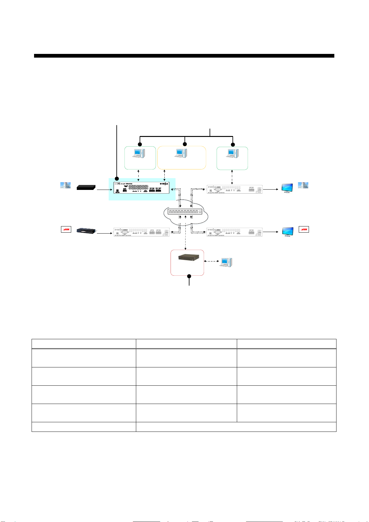
7System configuration example................................................................................................................. 17
7.1 Used as Network Extender................................................................................................................. 17
7.2 Used as Extender ............................................................................................................................... 18
8Precautions .............................................................................................................................................. 19
8.1 Attaching Rubber feet......................................................................................................................... 19
8.2 Installation........................................................................................................................................... 19
8.3 Cabling................................................................................................................................................ 20
8.3.1 Coaxial cable............................................................................................................................... 20
8.3.2 Fiber optic cable for extension.................................................................................................... 21
8.3.3 SFP+ optical transceiver............................................................................................................. 22
8.3.4 Connecting audio cable............................................................................................................... 23
8.3.5 RS-232C connector specification................................................................................................ 23
8.3.6 Connecting LAN cable ................................................................................................................ 24
8.3.7 DIN plug AC adapter with locking mechanism............................................................................ 25
8.4 Setting DIP switch............................................................................................................................... 27
9Basic Operation ....................................................................................................................................... 28
9.1 Control over RS-232C communication............................................................................................... 28
9.2 IP-NINJAR Configurator (Setting software for IP-NINJAR)................................................................ 29
9.3 Control over NJR-CTB (Control box for IP-NINJAR).......................................................................... 30
9.4 Setting items....................................................................................................................................... 31
9.5 Initialization ......................................................................................................................................... 32
9.6 Reboot ................................................................................................................................................ 32
10 Setting...................................................................................................................................................... 33
10.1 Output setting...................................................................................................................................... 34
10.1.1 Setting output mode.................................................................................................................... 34
10.1.2 Setting output deep color............................................................................................................ 34
10.1.3 Setting hot plug masking............................................................................................................. 35
10.2 Audio setting ....................................................................................................................................... 36
10.2.1 Muting digital audio ..................................................................................................................... 36
10.3 Input setting ........................................................................................................................................ 37
10.3.1 Setting SDI input audio group..................................................................................................... 37
10.3.2 SDI Dual Stream input video....................................................................................................... 37
10.4 RS-232C setting.................................................................................................................................. 38
10.4.1 RS-232C communication ............................................................................................................ 38
10.5 LAN setting ......................................................................................................................................... 39
10.5.1 LAN ............................................................................................................................................. 39
10.5.2 MAC address............................................................................................................................... 39
10.6 Information.......................................................................................................................................... 40
10.6.1 Input video status........................................................................................................................ 40
10.6.2 Input audio status........................................................................................................................ 40
10.6.3 Output status............................................................................................................................... 41

NJR-T01SDI User Guide
9
10.6.4 Sink device EDID ........................................................................................................................ 41
10.6.5 Version........................................................................................................................................ 41
11 Product specification................................................................................................................................ 42
12 Troubleshooting ....................................................................................................................................... 43

NJR-T01SDI User Guide
10
1 About this Guide
This user guide explains AV over IP Encoder for SDI (NJR-T01SDI).
This document also describes basic operations from external devices for controlling the NJR-T01SDI.
For other products of IP-NINJAR series, see [Table 1.1] Document for IP-NINJAR products.
PC for control
(For NJR-CTB)
LAN
Control box
(NJR-CTB)
IP network
Cable for extension
Source device
SDI
NJR-T01SDI (Encoder)IP-NINJAR series decoders
HDMI
IP-NINJAR series decoders
HDMI
Monitor
Monitor
LAN
PC for control
(For communication
command)
RS-232C
PC for control
(For communication
command)
RS-232C
1080p1080p
1080p
PC for control
(For IP-NINJAR Configurator)
LAN
10 GbE switch
Chapter 9
Chapter 9
Chapter 2 to 11
Source device
HDMI
IP-NINJAR series encoders
1080p
[Fig. 1.1] Document structure
[Table 1.1] Document for IP-NINJAR products
Model
User Guide
Command Guide
NJR-T01UHD / NJR-R01UHD NJR-T01UHD / NJR-R01UHD
User Guide
NJR-T01UHD / NJR-R01UHD
Command Guide
NJR-T04HD / NJR-R04HD NJR-T04HD / NJR-R04HD
User Guide
NJR-T04HD / NJR-R04HD
Command Guide
NJR-T01SDI NJR-T01SDI
User Guide
NJR-T01SDI
Command Guide
NJR-CTB NJR-CTB
User Guide NJR-CTB
Command Guide
IP-NINJAR Configurator IP-NINJAR Configurator User Guide

NJR-T01SDI User Guide
11
2 Included items
Ensure that all items illustrated below are included in the package.
If any items are missing or damaged, please contact IDK.
One (1) NJR-T01SDI (Encoder)
One (1) Cable clamp
Two (2) 5-pin terminal blocks
One (1) 3-pin terminal block
Four (4) Rubber feet
One (1) DIN plug AC adapter with
locking mechanism (3.9 ft. (1.2 m))

NJR-T01SDI User Guide
12
3 Precautions for shipping
The MM / SM model (NJR-T01SDI-MM / SM) has an SFP+ optical transceiver that makes it vulnerable to
damage caused by mishandling during shipment if it is improperly packaged.
If, for any reason, you need to ship the NJR, use the carton and cushion which were used at the time of
purchase. Make sure to plug the attached dust cap into the SFP+ optical transceiver. If you do not have the
carton and cushion, unplug the SFP+ optical transceiver from the NJR and plug the dust cap, and then put it
in an antistatic bag with enough cushion. Use the appropriate carton and cushion for shipping.
SFP+ optical transceiver
Unplugging
Plugging
Bail clasp
Open the bail clasp in
downward direction. Grasp
the transceiver and carefully
unplug it from the port.
Close the bail clasp
and slide it into the
port.
[Fig. 3.1] Removing and installing SFP+ optical transceiver

NJR-T01SDI User Guide
13
4 Product outline
The NJR-T01SDI is a 3G/HD/SD-SDI input-capable network encoder. It is designed to transmit SDI signals
for local and long-haul extension over fiber optic cables.
The NJR-T01SDI features a local monitor output, enabling video recording and previewing using an HDMI
monitor. It also offers RS-232C bidirectional communication and 1G network transmission.
IP network
Cable for extension
Source device
SDI
NJR-T01SDI (Encoder)
Source device
SDI
NJR-T01SDI (Encoder)
IP-NINJAR series decoders
HDMI
IP-NINJAR series decoders
HDMI
Monitor
Monitor
1080p
1080p
1080p
1080p
10 GbE switch
[Fig. 4.1] Signal transmission
Note:
The NJR-T01SDI has to be used with IP-NINJAR series decoders. The NJR-T01SDI cannot be connected to
FDX’s optic boards or OPF series products.
Two models are available depending on the cable you use.
Cable for extension Model number
Multimode fiber NJR-T01SDI-MM
Singlemode fiber NJR-T01SDI-SM

NJR-T01SDI User Guide
14
5 Features
■
Video
・Up to 1080p
・3G-SDI / HD-SDI / SD-SDI input
・Local monitor output
・Extension distances
Multimode fiber (OM3): Up to 984 ft. (300 m)
Singlemode fiber (OS1) : Up to 6.21 mi. (10 km) (up to 24.85 mi. (40 km, optional)
■
Audio
・SDI audio de-embedding
■
Communication
・Bidirectional RS-232C communication
・LAN
■
Network
・
Matrix switching, Videowall, Multiviewer, and Distribution over 10 GbE network
・
NJR-CTB (Control box for IP-NINJAR) enables encoder/decoder control and setting management.
・IP-NINJAR encoders and decoders can easily be added and replaced.
■
Others
・AC adapter with locking mechanism
Loop-through
Up to 16 ft. (5 m) Digital video/audio
HDMI DVI
SDI video/audio
3G-SDI
HD-SDI
SD-SDI 1Output
1 Output
Analog audio
LR balanced/unbalanced
1 Output
Digital video/audio/
communication for extension
Optical fiber
SDI video/audio
3G-SDI
HD-SDI
SD-SDI 1Input
RS-232C1Port
Analog audio
LR balanced/unbalanced
LAN
1Input
1Port 1 Output
NJR-T01SDI (Encoder)
D/A conversion
A/D conversion
TX
CPU
SDIreceiver
HDMI transmitter
Cable driver
Scan
converter
Video
*1 Audio D: Digital audio
*2 Audio A: Analog audio
(1)
SD-SDI : Up to 1312 ft. (400 m)/
HD-SDI : Up to 787 ft. (240 m)/
3G-SDI : Up to 459 ft. (140 m)
over 1694A (BELDEN RG-6) cable
(1)
Audio A*2
Video/audio D*1
Video/audio D*1
Video/audio D*1
Audio D*1
(2)
Multimode fiber (OM3) : Up to 984 ft. (300 m)
Singlemode fiber (OS1) : Up to 6.21 mi. (10 km)
Singlemode fiber (OS1) : Up to 24.85mi. (40 km, optional)
(2)
[Fig. 5.1] NJR-T01SDI Connection Diagram

NJR-T01SDI User Guide
15
6 Panels
① ② ③ ④ ③ ⑤ ⑥
⑧⑦ ⑨⑩ ⑪ ⑫ ⑬ ⑮⑭
[Fig. 6.1] NJR-T01SDI drawing
[Table 6.1] NJR-T01SDI features
#
Feature
Description
①
DIP switch
Switches internal connections of RS-232C signals.
【See: 8.4 Setting DIP switch】
②RS-232C connector Connector for RS-232C signals.
③Maintenance port Factory use only
④LEDs (green) ・POWER: Illuminates when power is supplied from the AC adapter.
・SIGNAL: Illuminates when video signals are valid; blinks
when video signals cannot be transmit correctly.
・TX : Blinks when a valid code is being sent to
IP-NINJAR series decoders, or 10 GbE switch.
・RX : Blinks when a valid code is being received from
IP-NINJAR series decoders, or 10 GbE switch.

NJR-T01SDI User Guide
16
[Table 6.2] NJR-T01SDI features (Cont’d)
#
Feature
Description
⑤
Audio input connector
Input connector (5-pin terminal block) for analog audio signals.
⑥
Audio output connector
Output connector for converted analog audio signal from SDI audio input
signal.
Connects to amplifiers, speakers, and mixers.
⑦
Cooling fan
Releases heat from the unit.
⑧
HDMI cable fixing hole
Retain HDMI cable by inserting cable clamps.
⑨HDMI output connector Output connector for converted HDMI signal from SDI input signal. Input
signals can be monitored by connecting to a sink device.
⑩
SDI input connector
Input connectors for 3G-SDI / HD-SDI / SD-SDI signals, interfaces with
source devices such as video cameras.
⑪SDI loop through output
connector
Output connector for loop through SDI signal.
Input signals can be monitored by connecting to a sink device.
⑫
I/O connector for
extension
I/O connector for digital signal extension. A fiber optic cable is used;
connects to IP-NINJAR series decoders or 10 GbE switch.
⑬LAN connector For external control by communication commands or web browsers.
⑭Frame ground Use for bonding chassis to local ground. An M4 screw is used.
⑮Power supply connector For use with provided power cable.

NJR-T01SDI User Guide
17
7 System configuration example
This chapter cites two system configuration examples.
7.1 Used as Network Extender
Using the NJR-T01SDI and other IP-NINJAR encoders/decoders with a 10 GbE switch enables extending,
distributing, matrix switching, videowall, and multiview.
①Video and audio signals are input to the SDI input connector of the NJR-T01SDI from an industrial video
device.
②NJR-T01SDI sends these signals to the 10 GbE switch over a fiber optic cable.
③10 GbE switch sends video and audio signals to the/several NJR-R01UHD / NJR-R04HD according to the
setting of NJR-CTB (control box for IP-NINJAR).
④NJR-R01UHD / NJR-R04HD outputs received video and audio signals from the HDMI output connector to
the monitor.
⑤Digital or analog audio of NJR-T01SDI can be selected and output from the analog audio output connector
of NJR-R01UHD.
NJR-T04HD
(Encoder)
HDMI / DVI
Up to 98 ft. (30 m)
Blu-ray player
1080pBlu-ray player
1080pBlu-ray player
1080pBlu-ray player
1080p
Multimode fiber (OM3)
: Up to 984 ft.
(300 m)
Singlemode fiber (OS1) : Up to 6.21 mi. (10 km)
Singlemode fiber (OS1) : Up to 24.85mi. (40 km, optional)
Cat6A cable : Up to 328 ft. (100 m)
4K monitor
HDMI / DVI
Up to 16 ft. (5 m)
IP network
PC for control
*3
NJR-T01SDI
(Encoder)
Control box
(NJR-CTB)
NJR-R01UHD
(Decoder)
LAN
*1
Local monitor
HDMI / DVI
Up to 16 ft. (5 m)
Microphone Mixer Analog audio
Speakers
Power amp.
Analog audio
10 GbE switch
1080p
4K@60
Speakers
Power amp.
Analog audio
LAN
*1
LAN
*2
LAN
*2
*1
Connect the control box to IP-NINJAR products or 10GbE switch.
*2
Connect the PC for control to IP-NINJAR to IP-NINJAR products or 10GbE switch.
*3
IP-NINJAR products are controlled from the PC for control.
NJR-R04HD
(Decoder)1080p ×4
Monitor ×4
HDMI / DVI
Up to 164 ft. (50 m)
SD-SDI : Up to 1312 ft. (400 m)/
HD-SDI
: Up to 787 ft. (240 m)/
3G-SDI
: Up to 459 ft. (140 m)
over 1694A (BELDEN RG-6) cable
Industrial video device
1080p
Local monitor
1080p
①
①
①
①
①
②
② ③
③
⑤
④
④
④
④
④
[Fig. 7.1] Used as network extender

NJR-T01SDI User Guide
18
7.2 Used as Extender
An NJR-T01SDI and IP-NINJAR series decoders are connected as Point To Point.
①Video and audio signals are input to the SDI input connector of the NJR-T01SDI from an industrial video
device.
②The NJR-T01SDI sends those signals to the NJR-R01UHD / NJR-R04HD over a fiber optic cable.
③NJR-R01UHD / NJR-R04HD outputs received video and audio signals from the HDMI output connector to
the monitor.
④Digital or analog audio of NJR-T01SDI can be selected and output from the analog audio output connector
of NJR-R01UHD.
⑤NJR-T01SDI and NJR-R01UHD / NJR-R04HD enables RS-232C communication, LAN communication,
and peripheral device control (such as projectors) by using a control device (such as PCs).
NJR-T01SDI
(Encoder)
Local monitor
HDMI / DVI
Up to 16 ft. (5 m)
Microphone Mixer
Analog audio
1080p
Speakers
Power amp.
Analog audio
SD-SDI : Up to 1312 ft. (400 m)/
HD-SDI
: Up to 787 ft. (240 m)/
3G-SDI : Up to 459 ft. (140 m)
over 1694A (BELDEN RG-6) cable
Industrial video device
1080p
Local monitor
1080p
PC for control
(Projector control)
LAN
RS-232C
Multimode fiber (OM3)
: Up to 984 ft.
(300 m)
Singlemode fiber (OS1) : Up to 6.21 mi. (10 km)
Singlemode fiber (OS1) : Up to 24.85mi. (40 km, optional)
Projector
1080p
HDMI / DVI
Up to 16 ft. (5 m)
NJR-R01UHD
(Decoder)
Speakers
Power amp.
Analog audio
LAN RS-232C
①
⑤
⑤
②
③
④
⑤
⑤
[Fig. 7.2] NJR-T01SDI and NJR-R01UHD (MM/SM)
NJR-R04HD
(Decoder)
1080p ×4
Monitor ×4
HDMI / DVI
Up to 164 ft. (50 m)
NJR-T01SDI
(Encoder)
SD-SDI : Up to 1312 ft. (400 m)/
HD-SDI : Up to 787 ft. (240 m)/
3G-SDI : Up to 459 ft. (140 m)
over 1694A (BELDEN RG-6) cable
Industrial video device
1080p
Multimode fiber (OM3)
: Up to 984 ft.
(300 m)
Singlemode fiber (OS1) : Up to 6.21 mi. (10 km)
Singlemode fiber (OS1) : Up to 24.85mi. (40 km, optional)
①
②
③
③
③
③
[Fig. 7.3] NJR-T01SDI and NJR-R04HD: Videowall
Using NJR-T01SDI and NJR-R01UHD
Videowall using NJR-T01SDI and NJR-R04HD

NJR-T01SDI User Guide
19
8 Precautions
Before using NJR-T01SDI, follow the precautions and instructions below.
8.1 Attaching Rubber feet
First, clean the bottom surface of the NJRT01SDI as needed, and then peal the release papers from the
rubber feet and place them in each of the four corners.
8.2 Installation
When installing the NJR-T01SDI, please observe the following precautions.
・Do not stack or place one NJR-T01SDI directly on top of another NJR-T01SDI.
・Do not block vent holes. To provide adequate ventilation, maintain sufficient clearances around the
NJR-T01SDI (1.2 in. (30 mm) or more).
・Do not install NJR-T01SDI in a closed space.
When placing them in an EIA rack-mount unit, prepare ventilating equipment to keep the ambient
temperature at 40°C / 104°F or less. If inadequately vented, the life of parts may be shortened and
operation may be affected.
(Exception: Installing to IDK’s rack mounting RM-SF, RM-SH)
・When you do not use an EIA rack-mount unit, maintain adequate clearances (1.2 in. (30 mm) or more) as
shown below.
Bad example
Good example
Good example
[Fig. 8.1] Necessary clearances
Maintain adequate clearances (1.2 in. (30 mm) or more) as shown below.

NJR-T01SDI User Guide
20
8.3 Cabling
When connecting the NJR-T01SDI to external devices, please observe the following precautions.
・Read manuals for the external devices.
・Before connecting cables to the NJR or an external device, dissipate static electricity by touching
grounded metal such as equipment racks before handling signal cables. Failure to observe this
precaution may result in ESD (electrostatic discharge) damage.
・Power all units off before connecting cables.
・Be sure to fully seat all plugs and connections and dress cables to reduce stress on connectors.
・Secure HDMI cables using cable clamps to prevent connectors from being accidently pulled out of ports.
①②③
Removing HDMI cable and cable clamp
Pull out while pressing
④
② ④ ⑤① ③
カチッ
Securing HDMI cable using cable clamp
[Fig. 8.2] Securing HDMI cable using cable clamp
8.3.1 Coaxial cable
Select the appropriate coaxial cable by referring to the following table.
[Table 8.1] Maximum extension distance when using BELDEN cable
SDI type Cable Max. extension distance
3G-SDI 1505A (BELDEN RG-59) 394 ft. (120 m)
1694A (BELDEN RG-6) 459 ft. (140 m)
HD-SDI 1505A (BELDEN RG-59) 656 ft. (200 m)
1694A (BELDEN RG-6) 787 ft. (240 m)
SD-SDI 1505A (BELDEN RG-59) 1083 ft. (330 m)
1694A (BELDEN RG-6) 1312 ft. (400 m)
Note:
Maximum extension distance depends on the characteristics of each source device and quality of each cable.
Table of contents
Other IDK Media Converter manuals