IDK NJR-P01U Series User manual

HDMI Encoder/Decoder
NJR-P01U Series
NJR-P01UF-T/NJR-P01UF-R
NJR-P01UC-T/NJR-P01UC-R
<User Guide>
Ver.1.0.0
Thank you for choosing our product.
To ensure the best performance of this product, please read this user guide fully and carefully before
using it and keep this manual together with the product for future reference as needed.
IDK Corporation

NJR-P01U Series User Guide
2
Trademarks
Blu-ray Disc and Blu-ray are trademarks of Blu-ray Disc Association.
The terms HDMI and HDMI High-Definition Multimedia Interface, and the HDMI Logo are trademarks or
registered trademarks of HDMI Licensing Administrator, Inc. in the United States and other countries.
Connection Reset and IP-NINJAR are registered trademarks of IDK Corporation in Japan.
All other company and product names mentioned in this manual are either registered trademarks or
®

NJR-P01U Series User Guide
3
Before reading this manual
All rights reserved.
Some information contained in this User guide such as exact product appearance, diagrams, menu
operations, and so on may differ depending on the product version.
This User g
website at: http://www.idkav.com
The reference manual consists of the following two volumes:
User guide (this document):
Provides explanations and procedures for operations, installation, connections among devices,
I/O adjustment and settings.
Command guide: Please download the command guide from the website above.
Provides explanations and procedures for external control using RS-232C and LAN communications.
FCC STATEMENT
This equipment has been tested and found to comply with the limits for a Class A digital device, pursuant to
part 15 of the FCC Rules. These limits are designed to provide reasonable protection against harmful
interference when the equipment is operated in a commercial environment. This equipment generates, uses,
and can radiate radio frequency energy and, if not installed and used in accordance with the instruction
manual, may cause harmful interference to radio communications. Operation of this equipment in a residential
area is likely to cause harmful interference, in which case the user will be required to correct the interference
at his own expense.
CE MARKING
This equipment complies with the essential requirements of the relevant European health, safety and
environmental protection legislation.
WEEE MARKING
Waste Electrical and Electronic Equipment (WEEE), Directive 2002/96/EC
(This directive is only valid in the EU.)
This equipment complies with the WEEE Directive (2002/96/EC) marking requirement.
The left marking indicates that you must not discard this electrical/electronic equipment in
domestic household waste.
The lasers in this product meet Class 1 Laser Safety per FDA/CDRH and
EN (IEC) 60825 laser safety standards which specifies design safety.

NJR-P01U Series User Guide
4
Safety Instructions
Read and understand all safety and operating instructions before using this product. Follow all instructions
and heed all warnings/cautions.
Enforcement Symbol Description
Indicates the presence of a hazard that may result in death or serious
personal injury if the warning is ignored or the product is handled
incorrectly.
Indicates the presence of a hazard that may cause minor personal
injury or property damage if the caution is ignored or the product is
handled incorrectly.
Symbol Description Example
Caution
This symbol is intended to alert the user. (Warning and caution)
Electrical
Hazard
Prohibited
This symbol is intended to prohibit the user from specified actions.
Do not
disassemble
Instruction
This symbol is intended to instruct the user.
Unplug

NJR-P01U Series User Guide
5
For lifting heavy products:
I
n
s
t
r
u
c
t
i
o
n
Lifting must be done by two or more personnel.
To avoid injury: When lifting the product, bend your knees, keep your back straight and get close to it with two or
more persons.
For installing and connecting products:
Prohibited
Do not place the product upon a surface that may give way or that may become
unstable.
Install the product in a secure and stable place to prevent it from falling and possibly causing injury.
Secure the product if installing in locations prone to vibration or movement.
Otherwise, it may move unexpectedly or it may fall and lead to injury.
Instruction
Installation work must be performed by professionals.
The product is intended to be installed by skilled technicians. For installation, please contact a system integrator
or IDK. Improper installation may lead to the risk of fire, electric shock, injury, or property damage.
Insert the power plug into an outlet that is unobstructed.
Unobstructed access to the plug enables unplugging the product in case of any extraordinary failure, abnormal
situation or for easy disconnection during extended periods of non-use.
Insert the power plug into an appropriate outlet completely.
If the plug is partially inserted, arching may cause the connection to overheat, increasing the risk of electrical
shock or fire. Do not use a damaged plug or connect to a damaged outlet.
Unplug the product from the AC power source during installation or service.
When connecting peripheral devices to this product, unplug all involved devices from outlets. Ground potential
differences may cause fire or other difficulties.
For operating products:
Prohibited
Keep out any foreign objects.
To avoid fire or electric shock, do not permit foreign objects, such as metal and paper, to enter the product from
vent holes or other apertures.
For power cable/ plug:
Do not scratch, heat, or modify, including splicing or lengthening them.
Do not pull, place heavy objects on them, or pinch them.
Do not bend, twist, tie or clamp them together forcefully.
Misuse of the power cable and plug may cause fire or electric shock. If power cables/plugs become damaged,
contact your IDK representative.
Do not
d
i
s
a
s
s
e
m
b
l
e
Do not repair, modify or disassemble.
Since the product includes circuitry that uses potentially lethal, high voltage levels, disassembly by unauthorized
personnel may lead to the risk of fire or electric shock. For internal inspection or repair, contact your IDK
representative.
D
o
n
o
t
t
o
u
c
h
Do not touch the product and connected cables during electrical storms.
Contact may cause electric shock
Instruction
Clean the power plug regularly.
If the plug is covered in dust, it may increase the risk of firer.

NJR-P01U Series User Guide
6
If the following problem occurs:
Unplug
Unplug immediately if the product smokes, makes unusual noise, or produces a
burning odor.
If you continue to use the product under these conditions, it may cause electric shock or fire.
Unplug immediately if the product is damaged by falling or having been dropped.
If you continue to use the product under these conditions, it may increase the risk of electrical shock or fire. For
maintenance and repair, contact your IDK representative.
Unplug immediately if water or other objects are directed inside.
If you continue to use the product under these conditions, it may increase the risk of electrical shock or fire. For
maintenance and repair, contact your IDK representative.

NJR-P01U Series User Guide
7
For installing and connecting products:
Prohibited
Do not place the product in a location where it will be subjected to high
temperatures.
If the product is subjected to direct sunlight or high temperatures while under operation, it may affect the
product s performance and reliability and may increase the risk of fire.
Do not store or operate the product in dusty, oil smoke filled, or humid place.
If the product is placed near humidifiers or in a dusty area, it may increase the risk of fire or electric shock.
Do not block the vent holes.
If ventilation slots are blocked, it may cause the product to overheat, affecting performance and reliability and
may increase the risk of fire.
Do not place or stack heavy items on the product.
Failure to observe this precaution may result in damage to the product and other property and may lead to the
risk of personal injury.
Do not exceed ratings of outlet and wiring devices.
Exceeding the rating of an outlet may increase the risk of fire and electric shock.
N
o
w
e
t
h
a
n
d
s
Do not handle power plug with wet hands.
Failure to observe this precaution may increase the risk of electrical shock.
Instruction
Use and store the product within the specified temperature/humidity range.
If the product is used outside the specified range for temperature and humidity continuously, it may increase the
risk of fire or electric shock.
Do not place the product at elevations of 1.24 mi. (2,000 m) or higher above sea
level.
Failure to do so may shorten the life of the internal parts and result in malfunctions.
When mounting the product into the rack, provide sufficient cooling space.
Mount the product in a rack meeting EIA standards, and maintain spaces above and below for air circulation. For
your safety as required, attach an L-shaped bracket in addition to the panel mount bracket kit to improve
mechanical stability.
Never insert screws without the rubber feet into the threaded holes on the bottom
of the product.
Never insert screws without the rubber feet into the threaded holes on the bottom of the product. Doing so may
lead to damage when the screws contact electrical circuitry or components inside the product.
Reinstall the originally supplied rubber feet using only the originally supplied screws.
For operating products:
P
r
o
h
i
b
i
t
e
d
Use only the supplied power cable and AC adapter.
Do not use the supplied power cable and AC adapter with other products.
If non-compliant adapter or power cables are used, it may increase the risk of fire or electrical shock.
Unplug
If the product won t be used for an extended period of time, unplug it.
Failure to observe this precaution may increase the risk of fire.
Unplug the product before cleaning.
To prevent electric shock.
Instruction
If cooling fan stops, power off the product and contact us.
Failure to do so may rise internal temperature and increase the risk of malfunction, fire, or electric shock.
Clean the vent holes regularly.
If the vent holes of the cooling fan is covered in dust, internal temperature rises and it may increase the risk of
malfunction, fire, or electric shock.

NJR-P01U Series User Guide
8
1 About this Guide ...................................................................................................................................... 10
2 Included Items.......................................................................................................................................... 11
3 Precautions for shipping .......................................................................................................................... 12
4 Product Outline ........................................................................................................................................ 13
5 Features ................................................................................................................................................... 14
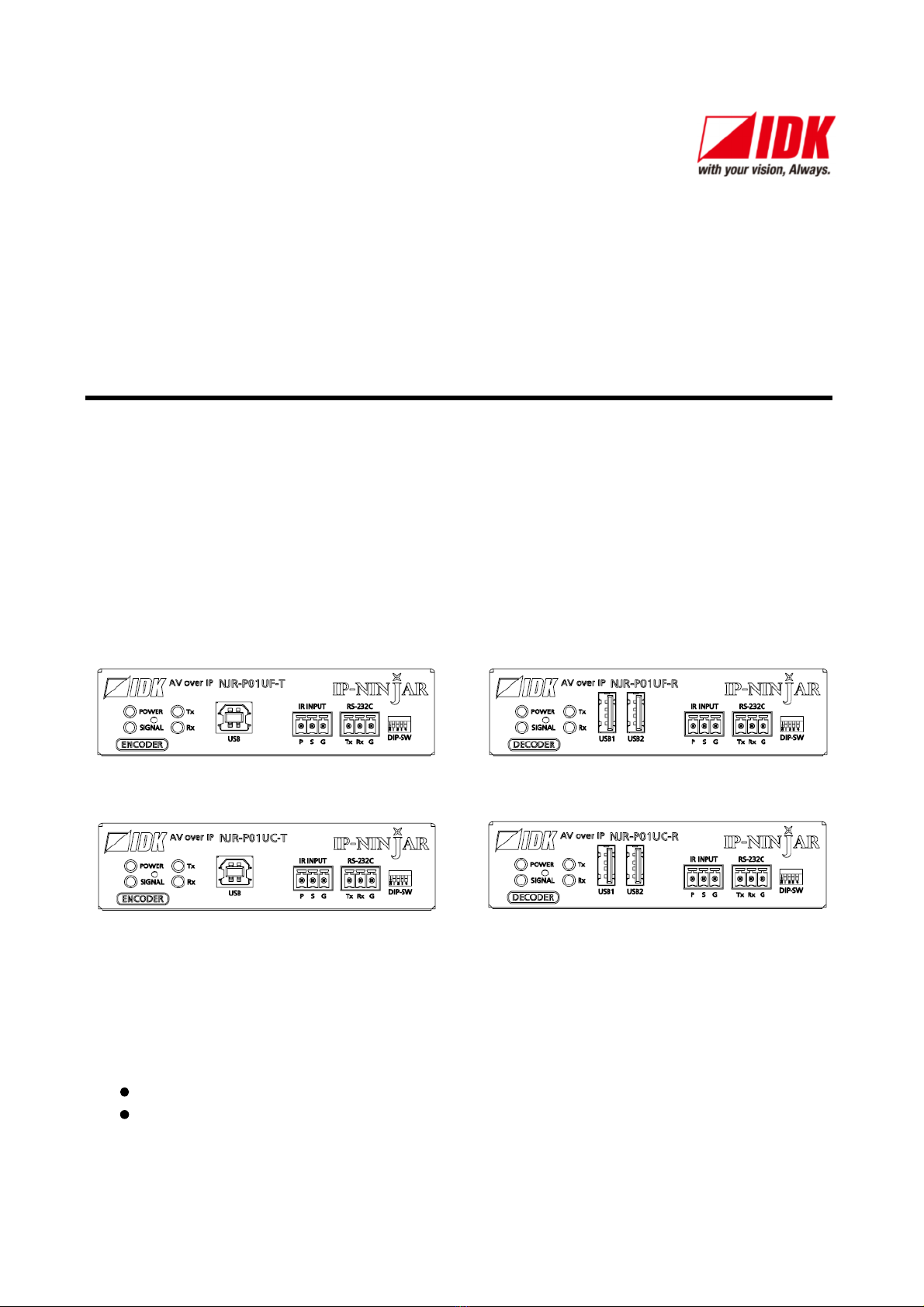
6 Panels ...................................................................................................................................................... 16
6.1 NJR-P01U-T (Encoder) ...................................................................................................................... 16
6.1.1 NJR-P01UF-T (Fiber optic model) .............................................................................................. 16
6.1.2 NJR-P01UC-T (CAT model)........................................................................................................ 18
6.2 NJR-P01U-R (Decoder)...................................................................................................................... 20
6.2.1 NJR-P01UF-R (Fiber optic model).............................................................................................. 20
6.2.2 NJR-P01UC-R (CAT model) ....................................................................................................... 22
7 System configuration example................................................................................................................. 24
7.1 Used as Network Extender ................................................................................................................. 24
7.2 Used as Extender ............................................................................................................................... 25
8 Precautions .............................................................................................................................................. 27
8.1 Attaching Rubber feet ......................................................................................................................... 27
8.2 Installation........................................................................................................................................... 27
8.3 Cabling................................................................................................................................................ 28
8.3.1 HDMI cable ................................................................................................................................. 29
8.3.2 Fiber optic cable for extension .................................................................................................... 30
8.3.3 SFP+ optical transceiver ............................................................................................................. 31
8.3.4 Category cable for extension ...................................................................................................... 32
8.3.5 Connecting RS-232C cable......................................................................................................... 32
8.3.6 Connecting LAN cable ................................................................................................................ 33
8.3.7 Connecting USB.......................................................................................................................... 34
8.3.8 Connecting IR cable.................................................................................................................... 34
8.3.9 Supplying power.......................................................................................................................... 35
8.4 Setting DIP switch............................................................................................................................... 37
9 Basic Operation ....................................................................................................................................... 38
9.1 Control over RS-232C communication ............................................................................................... 39
9.2 Controlled by IP-NINJAR Configurator ............................................................................................... 40
9.3 Controlled by NJR-CTB ...................................................................................................................... 41
9.4 Setting Items ....................................................................................................................................... 42
9.5 Initialization ......................................................................................................................................... 43
9.6 Reboot ................................................................................................................................................ 43
10 Setting ...................................................................................................................................................... 44
10.1 Input .................................................................................................................................................... 45
10.1.1 Non-signal input monitoring ........................................................................................................ 45
10.1.2 HDCP input enabled/disabled ..................................................................................................... 46
10.2 Output ................................................................................................................................................. 47
10.2.1 Output mode ............................................................................................................................... 47
10.2.2 HDCP output ............................................................................................................................... 47
10.2.3 Hot plug ignoring duration ........................................................................................................... 48
10.3 Audio................................................................................................................................................... 49
10.3.1 Muting digital audio ..................................................................................................................... 49
10.3.2 Selecting output audio................................................................................................................. 49

NJR-P01U Series User Guide
9
10.4 EDID ................................................................................................................................................... 50
10.4.1 EDID resolution ........................................................................................................................... 50
10.4.2 Copying EDID ............................................................................................................................. 52
10.4.3 Selecting WXGA mode ............................................................................................................... 52
10.4.4 Deep Color .................................................................................................................................. 53
10.4.5 Audio format................................................................................................................................ 53
10.4.6 Speaker configuration ................................................................................................................. 54
10.5 IR control............................................................................................................................................. 54
10.6 RS-232C ............................................................................................................................................. 55
10.6.1 RS-232C communication ............................................................................................................ 55
10.7 LAN ..................................................................................................................................................... 56
10.7.1 LAN ............................................................................................................................................. 56
10.7.2 MAC address .............................................................................................................................. 56
10.8 Information.......................................................................................................................................... 57
10.8.1 Input status.................................................................................................................................. 57
10.8.2 Output status ............................................................................................................................... 58
10.8.3 Monitor EDID............................................................................................................................... 59
10.8.4 Version ........................................................................................................................................ 60
11 Product specification................................................................................................................................ 61
11.1 NJR-P01UF-T/R.................................................................................................................................. 61
11.2 NJR-P01UC-T/R ................................................................................................................................. 62
12 Troubleshooting ....................................................................................................................................... 63

NJR-P01U Series User Guide
10
1
This user guide explains how to use the NJR-P01UF/NJR-P01UC ( NJR- and
about external control through the IP-NINJAR Configurator and NJR-CTB. The NJR-P01UF-T/NJR-P01UC-T
is an encoder while the NJR-P01UF-R/NJR-P01UC-R is a decoder.
If other IP-NINJAR series products are connected, refer to each User Guide.
Models
Model Type Model number
Fiber optic
No SFP+ optical transceiver Encoder NJR-P01UF-T
Decoder NJR-P01UF-R
Multimode fiber Encoder NJR-P01UF-T-MM
Decoder NJR-P01UF-R-MM
Singlemode fiber Encoder NJR-P01UF-T-SM
Decoder NJR-P01UF-R-SM
CAT (No SFP+ transceiver) Encoder NJR-P01UC-T
Decoder NJR-P01UC-R

NJR-P01U Series User Guide
11
2
Ensure all items below are included in the package.
If any items are missing or damaged, please contact IDK.
NJR-P01UF/C-T
NJR-P01UF/C-R
SFP+ optical transceiver
DIN plug AC adapter with locking
mechanism (4 ft. (1.2 m))
Cable clamp
Rubber feet
3-pin captive screw connector
Item NJR-P01UF-T NJR-P01UF-R NJR-P01UC-T NJR-P01UC-R
MM/SM MM/SM
Main unit 1 1 1 1 1 1
SFP+ optical transceiver 1 1
DIN plug AC adapter with locking
mechanism (3.9 ft. (1.2 m)) 1 1 1 1 1 1
Cable clamp 1 1 1 1 1 1
Rubber feet 4 4 4 4 4 4
3-pin captive screw connector 2 2 2 2 2 2
[Fig. 2.1] Included items
Tip:
Dust caps are attached to SFP+ optical transceiver and the connector.
These caps will be used for shipping the NJR-P unit.

NJR-P01U Series User Guide
12
3
The MM/SM model (NJR-P01UF-T/R-MM/SM) has an SFP+ optical transceiver that is vulnerable to damage
caused by mishandling during shipment if it is improperly packaged.
If, for any reason, you need to ship the device, remove the transceiver from the device and plug the dust cap
into the transceiver and the connector. Put the removed transceiver in an electrostatic bag with enough
cushion and keep the bag and device together in a box.
To install a transceiver:
Make sure the bale clasp is closed.
Line up the transceiver with the port and slide it into
the port until you hear a click.
Removing a transceiver:
Open the bale clasp and pull the transceiver out
of the port.
[Fig. 3.1] Removing and installing SFP+ optical transceiver
Note:
When installing the SFP+ transceiver, push it firmly and ensure that it is completely seated and the bale clasp
is locked. Do not open the bale clasp except for removing the transceiver.
RemovingInstalling
SFP+ transceiver
Bale clasp

NJR-P01U Series User Guide
13
4
The NJR-P is an AV over IP solution for high definition signal transmission via fiber optic cables or category
cables. This 4K solution leverages 10 Gb Ethernet switches and enables signal management of 4K@60
(4:4:4) signals with zero latency. USB HID class is also supported for KVM extension application. Additionally,
via the NJR-P, the NJR-CTB can be controlled using an IR cable (IR-P01-R) and recommended remote
controller. The NJR-P features LAN/RS-232C bidirectional communication.
The NJR-P01UC can be powered from PoE-supported 10 GbE switch over a Category cable; this feature
eliminates the need for AC adapter.
IP net
Cable for extension
Source device
HDMI
NJR-P01UF-T
Source device
HDMI
NJR-P01UC-T
NJR-P01UF-R
HDMI
NJR-P01UC-R
HDMI
4K monitor
Monitor
4K@60
1080p
4K@60
1080p
[Fig. 4.1] HDMI signals transmission
Note:
Use this product with a combination of NJR-P or IP-NINJAR series products.
It cannot be connected to OPF or FDX series.

NJR-P01U Series User Guide
14
5
Video
Up to 4K@60 (4:4:4)
HDCP 1.4/2.2
HDR
Transmission distances
Fiber optic cable (NJR-P01UF-T-MM/SM, NJR-P01UF-R-MM/SM)
Multimode fiber (OM3) : Up to 984 ft. (300 m)
Singlemode fiber (OS1) : Up to 6.21 mi. (10 km) (Up to 24.85 mi. (40 km, optional))
Category cable (NJR-P01UC-T, NJR-P01UC-R)
Cat6A : Up to 328 ft. (100 m)
Communication
Bidirectional RS-232C
LAN
USB HID class
Network
10 Gb switch allows: extension, distribution, matrix switching, videowall, and multiview
Controllable through network using NJR-CTB
IP-NINJAR encoders and decoders can easily be added and replaced
Preset controls that are registered in the NJR-CTB can be executed using an IR cable (IR-P01-R) and
recommended remote controller.
Others
EDID emulation
DDC buffer
Connection Reset
AC adapter with locking mechanism
PoE power supplied (PD) (NJR-P01UC-T, NJR-P01UC-R)

NJR-P01U Series User Guide
15
Transmitter
EDID
emulator
NJR-P01UF-T
NJR-P01UF-T-MM
NJR-P01UF-T-SM
NJR-P01UC-T
Digital video/audio/
communication for extension
Fiber optic/CAT
Output
1
Up to 16 ft. (5 m)
LAN Port
1
RS-232C Port
1
IR Port
1
*1
Audio D: Digital audio
Digital video/audio
HDMI DVI Input
1
Receiver
Video/Audio D
*1
Scan
converter
Video Multimode fiber
(OM3)
: Up to 984 ft.
(300 m)
Singlemode fiber (OS1) : Up to 6.21 mi.
(10 km)
Singlemode fiber (OS1) : Up to 24.85 mil. (40 km, optional)
Cat6A cable : Up to 328 ft.
(100 m)
USB Port
1
CPU
[Fig. 5.1] NJR-P01UF/C-T diagram
Digital video/audio
HDMI DVI Output
1
Digital video/audio/
communication for extension
Fiber optic/CAT
Input
1
LAN Port
1
RS-232C Port
1
*1
Audio D
: Digital audio
*2
Audio A : Analog audio
Up to 16 ft. (5 m)
Receiver
Audio A
*2
Transmitter
Audio D
*1
CPU
Video/Audio
Scan
converter
Video
Multimode fiber
(OM3)
: Up to 984 ft.
(300 m)
Singlemode fiber (OS1) : Up to 6.21 mi.
(10 km)
Singlemode fiber (OS1) : Up to 24.85 mil. (40 km, optional)
Cat6A cable : Up to 328 ft.
(100 m)
USB Ports
2
IR Port
1
NJR-P01UF-R
NJR-P01UF-R-MM
NJR-P01UF-R-SM
NJR-P01UC-R
[Fig. 5.2] NJR-P01UF/C-R diagram

NJR-P01U Series User Guide
16
6
6.1 NJR-P01U-T (Encoder)
6.1.1 NJR-P01UF-T (Fiber optic model)
[Fig. 6.1] NJR-P01UF-T drawing
[Table 6.1] NJR-P01UF-T features
# Feature Description
HDMI input connector Input connectors for HDMI signal to connect to a source devices, such as
Blu-ray players
HDMI cable fixing hole Fixes HDMI cables by inserting provided cable clamps.
I/O connector for
extension
I/O connector for digital signal extension
A fiber optic cable is used; connects to an IP-NINJAR fiber model decoder
or 10 GbE switch
LAN connector For LAN signals
RS-232C connector For RS-232C signals
USB connector Connector for USB HID signal
Connects to a USB host directly.
IR connector Connector for receiving IR signal
The signal of a remote controller will be sent to the NJR-CTB over the IR
cable (IR-P01-R).
DIP switch Switches internal connections of RS-232C signals.
See: 8.4 Setting DIP switch

NJR-P01U Series User Guide
17
[Table 6.2] NJR-P01UF-T features (Cont d)
# Feature Description
LEDs (green) POWER : Illuminates when power is supplied from the AC adapter.
SIGNAL : Illuminates when video signals are valid; blinks when video
signals cannot be transmitted correctly.
TX : Blinks when a valid code is being sent to an IP-NINJAR fiber
model decoder or 10 GbE switch.
RX : Blinks when a valid code is being received from
an IP-NINJAR fiber model decoder or 10 GbE switch.
Power supply connector For the provided AC adapter
Frame ground Use for bonding chassis to local ground. M3 screws are used

NJR-P01U Series User Guide
18
6.1.2 NJR-P01UC-T (CAT model)
[Fig. 6.2] NJR-P01UC-T drawing
[Table 6.3] NJR-P01UC-T features
# Feature Description
HDMI input connector Input connectors for HDMI signal to connect to a source devices, such as
Blu-ray players
HDMI cable fixing hole Fixes HDMI cables by inserting provided cable clamps.
I/O connector for
extension
I/O connector for digital signal extension
A category cable is used; connects to an IP-NINJAR CAT model decoder
or 10 GbE switch
PoE is supported.
See: 8.3.9 Supplying power
LAN connector For LAN signals
RS-232C connector For RS-232C signals
USB connector Connector for USB HID signal
Connects to a USB host directly.
IR connector Connector for receiving IR signal
The signal of a remote controller will be sent to the NJR-CTB over the IR
cable (IR-P01-R).
DIP switch Switches internal connections of RS-232C signals.
See: 8.4 Setting DIP switch

NJR-P01U Series User Guide
19
[Table 6.4] NJR-P01UC-T features (Cont d)
# Feature Description
LEDs (green) POWER : Illuminates when power is supplied from the AC adapter.
SIGNAL : Illuminates when video signals are valid; blinks when video
signals cannot be transmitted correctly.
TX : Blinks when a valid code is being sent to an IP-NINJAR CAT
model decoder or 10 GbE switch.
RX : Blinks when a valid code is being received from
an IP-NINJAR CAT model decoder or 10 GbE switch.
Power supply connector For the provided AC adapter
Frame ground Use for bonding chassis to local ground. M3 screws are used

NJR-P01U Series User Guide
20
6.2 NJR-P01U-R (Decoder)
6.2.1 NJR-P01UF-R (Fiber optic model)
[Fig. 6.3] NJR-P01UF-R drawing
[Table 6.5] NJR-P01UF-R features
# Feature Description
HDMI output connector Output connector for HDMI signals
Connects to a sink device, such as an LCD monitor.
HDMI cable fixing hole Fixes HDMI cables by inserting provided cable clamps.
I/O connector for
extension
I/O connector for digital signal extension
A fiber optic cable is used; connects to an IP-NINJAR fiber model encoder
or 10 GbE switch
LAN connector For LAN signals
RS-232C connector For RS-232C signals
USB connector Connector for USB HID signal
Connects to a keyboard and mouse directly.
IR connector Connector for receiving IR signal
The signal of a remote controller will be sent to the NJR-CTB over the IR
cable (IR-P01-R).
DIP switch Switches internal connections of RS-232C signals.
See: 8.4 Setting DIP switch
This manual suits for next models
8
Table of contents
Other IDK Media Converter manuals