manuals.online logo
Brands
  1. Home
  2. •
  3. Brands
  4. •
  5. IDTECH
  6. •
  7. Barcode Reader
  8. •
  9. IDTECH Econoscan User manual

IDTECH Econoscan User manual

CHECK VERSION
IDT
CH
RR
80042504-001
Rev.A
R04/05
#464
DEFAULT
WARNING
Please power down the host computer before
connecting this scanner. This is critical to
protecting both the scanner and the host from
serious damage
and Compliance :
This device has been tested and found comply with the
limits for a Class B digital pursuant to part 15 of the FCC
Rules.
This device has been tested and found compliant
with the following listed standards as required by the
EMC Directive 89/336/EEC as amended by directives
92/EEC and 93/68/EEC: EN55022(1992); EN55024(1992);
EN55082-1 (1998)
All rights are reserved. No part of this document may
be photocopied, reproduced, or translated into other
language without prior noticed from the owner.
2005 International Technologies & Systems Corporation.
The information contained herein is provided to the user
as a convenience. While every effort has been made to
ensure accuracy, ID TECH is not responsible for damages
that might occur because of errors or omissions, including
any loss of profit or other commercial damage. The
specifications described herein were current at the time of
publication, but are subject to change at any time without
prior notice.
ID TECH is a registered trademark of
EconoScan and Value through Innovation
are trademarks of
International Technologies
& Systems Corporation
International Technologies & Systems
Corporation
c
CONTENTS
TABLE OF CONTENTS ----------------------------------------------------------------------- 1
INTRODUCTION, EZ TROUBLESHOOTING ----------------------- --- ------------ 2~3
CLONING MODE ---------------------------------------------------------------------------- 4~5
GETTING STARTED
>>> HOW TO FIX THE SCANNER TO THE TERMINAL ----------------------- 6~7
>>> HOW TO CHANGE A CABLE --------------------------------------------------------- 7
>>> HOW TO SETUP THE PARAMETER.----------------------------------------------- 8
GROUP 1 >>>> INTERFACES SELECTION, COMPUTER TYPE, DEFAULT. ---------- 9
GROUP 2 >>>> READING MODE SETTING. -------------------------------------------- ------ 10
GROUP 3 >>>> CHECK VERSION, BEEP TONE, CAPLOCK MODE.-------------------- 11
GROUP 4 >>>> PREAMBLE AND POSTAMBLE.----------------------------------------------- 12
GROUP 5 >>>> ACCURACY ADJUSTMENT.---------------------------------------------------- 13
GROUP 6 >>>> ENABLE AND DISABLE CODE ID.------------------------------------------- 14
GROUP 7 >>>> SYMBOLOGIES CODE ID IDENTIFIER., SET ID ------------------------ 15
GROUP 8~9 >> CODE ID CONFIGURATION: SET CODE ID ----------------------- 16~17
GROUP 10 >>> DELAY BETWEEN BLOCK AND CHARACTER.-------------------------- 18
GROUP 11 >>> TERMINATOR AND KEYBOARD LAYOUT. -------------------------------- 19
GROUP 12 >>> RS232-BAUD RATE, DATA BITS & PARITY,-------------------------------- 20
GROUP 13 >>> RS232-STOP BIT,HANDSHAKING, ACK/NAK, FLOW CONTROL--- 2 1
GROUP 14 >>> WAND EMULATION PARAMETER SETTING. --------------------------- 22
SYMBOLOGIES FORMATING (GROUP 15~ GROUP 31). ----------------------- 23
GROUP 15 ~16>ENABLE AND DISABLE SYMBOLOGIES. --------------------------- 24~25
GROUP 17 >>> CHINA POST CODE ( TOSHIBA CODE), CODE 32.----------------- 26
APPEND 1 >>> NUMERIC TABLE, MIN/MAX LENGTHS SETTING -------------------- 27
GROUP 18 >>> UK PLESSEY CODE, MSI CODE. ----------------------------------------- 28
APPEND 1 >>> NUMERIC TABLE, MIN/MAX LENGTHS SETTING ------------------ 29
GROUP 19 >>> CODE IATA, CODE93.TELEPEN.-------------------------------------------- 30
APPEND 1 >>> NUMERIC TABLE, MIN/MAX LENGTHS SETTING -------------------- 31
GROUP 20 >>> INTERLEAVED 2 OF 5, CODE 11 .----------------------------------------- 32
APPEND 1 > >> NUMERIC TABLE, MIN/MAX LENGTHS SETTING ------------------- 33
GROUP 21 >>> CODABAR.------------------------------------------------------------------------- 34
APPEND 1 >>> NUMERIC TABLE, MIN/MAX LENGTHS SETTING---------------------- 35
GROUP 22 >>> ABC-CODABAR, CX CODE ----------------.--------------------------------- 36
GROUP 23 >>> CODABAR COUPLING, ------------------------------------------------------- 37
GROUP 24 >>> CODE 128, STANDARD CODE 39, FULL ASCII CODE 39.----------- 38
APPEND 1 >>> NUMERIC TABLE, MIN/MAX LENGTHS SETTING -------------------- 39
GROUP 25 >>> INDUSTRIAL 2 OF 5, MATRIX 2 OF 5.------------------------------------- 40
APPEND 1 >>> NUMERIC TABLE, MIN/MAX LENGTHS SETTING--------------------- 41
GROUP 26 >>> UPC-E. ----------------------------------------------------------------------------- 42
GROUP 27 >>> UPC-E(0), (1) ,UPC-E & UPC-A EXPAND ----------------------------- 43
GROUP 28 >>> UPC-A..----------------------------------------------------------------------------- 44
GROUP 29 >>> EAN 8. ------------------------------------------------------------------------------ 45
GROUP 30 >>> EAN 13 ----------------------------------------------------------------------------- 46
GROUP 31 >>> EAN/ UCC 128 -------------------------------------------------------------------- 47
GROUP 32 ~ 39 >>>> FULL ASCII TABLE ( CODE 39 --------------------- 48 ~55
GROUP 40 >>>>> NUMERIC ( CODE 39 ) TABLE. --------------------------- 56
GROUP 41~ 42 >>>> FUNCTION CODE ( CODE 39 ) FOR PC AT.------ 57~58
GROUP 43~ 46 >>>> TROUBLE SHOOTING --------------------------------- 59~62
Ms6262 CONTROL CODE LIST FOR Rs232. ----------------------------------------- 63
GENERAL
SETTING GROUP
1
GENERAL
INTRODUCTION
EZ TROUBLESHOOTING
. A001$
2
ID TECH's EconoScan CCD Scanner is specially designed to
deliver high-end bar code reading performance at the lowest
possible price. The scanner utilizes exceptional decoding
technology. One-time settings are easily made by scanning set-up
bar codes in this handy user's manual. The EconoScan enables
quick contact scanning of bar codes up to 3.5 inches in length.At
a scan rate of 150 scans per second, low-quality or damaged bar
codes, as well as small or high-density bar codes, can be read
with exceptional speed and accuracy. This rugged scanner contains
no moving parts, yet it is exceptionally lightweight and designed to
fit comfortably in the hand for extended periods of usage. The
cable is detachable for easy replacement or theuse of multiple
interfaces.
The EconoScan has many settings that can be used to conform the
unit to the requirements of a particular application. For most usages,
however,the default settings programmed into the unit at the factory
are appropriate.It is not recommended that the default settings be
changed unless thereis a specific need to alter the characteristics of
the scanner's performance.
The EconoScan is easy to install and use. Many problems
encountered can be attributed to a wrong setting that has been
programmed into the scanner. Before troubleshooting the problem,
try this:
1. Unplug the cable from the host computer.
2. Plug the cable back into the host computer.
3. Reset the scanner settings to DEFAULT (Group 1).
If these steps do not resolve the problem, please refer to the
troubleshooting table on the next page. If this fails to correct the
problem, please consult the troubleshooting section beginning on
page 59 for further assistance.
3
eKind of T oubl s r
Comter Ty
pupe
p
( G ou 1)r
n rf cSel t on
Itea es ec is
r
(G oup 1)
ettinocr
Sg Pr edue
ave com tdh not ple e
( Setting eed T e
N ripl
S scng )
hot anni
- -- -- --- -----
-- --- ---- --
G - 4,5,8,9,
roup 17,
19,20,22,23
18, ,24,
25,31
imitaio ofength of
L t n l
e ar cod
th b e
ypto sS m m
R 2 t os23 Prooc l
i
Comun cation setting
bprolem
No
1
2
3
4
Solutions
ur 2
Fige
5
Scanner seems to be performing as usual, but no data is being output.
1. Unplug the cable from the host computer.
2. Plug the cable back into the host computer.
3. Set the scanner to the exact computer type immediately.
The scanner does not scan when the trigger is depressed.
1. Unplug the cable from the host computer.
2. Plug the cable back into the host computer.
3. Set the scanner to the correct interface. Thecable
needs to match the interface.
Most settings require only a single bar code , but a few need several different
bar codes to be scanned in order to completely define a setting. They are:
1. Preamble, Postamble (Group 4)
2.Accuracy Adjustment (Group 5)
3. Customer ID Configuration (Groups 8 and 9)
4. Min/Max Length (Groups 17, 18, 19, 20, 21, 22, 24, 25)
5. ABC Codabar (Groups 22 and 23)
6. CX-Codabar (Groups 22 and 23)
7. Coupling Codabar (Groups 22 and 23)
8. EAN 128 (Group 31)
1. Follow the procedures for these settings at the
appropriate pages.
2. The scanner will beep three times for an incomplete
setting.
3. Scan RESET to try a setting again.
The scanner is reading correctly, except for certain bar codes of a
certain length
Reset the Min/Max setting for the bar code symbology
affected.
The scanner appears to be working in the RS-232 interface, but no
data is m being output.
Ensure the correct RS-232 communication parameters
have been set: Baud Rate, Handshaking, Stop Bits, Data
Bits, andParity. These settings must be the same for both
the scanner and the host.
CLONING MODE
WHAT IS CLONING MODE?
CLONING duplicates a scanner's settings in other scanners. It can
save time when a number of scanners must be programmed to the
same settings.
HOW SHOULD THE CLONING WORK?
1. Using this guide, make all the necessary settings for one scanner.
2. Scan the CLONING MODE bar code shown in Figure 1.
3. When CLONING MODE is scanned, all setup parameters will be
converted to alphanumeric characters and shown on the monitor.
4. Using a bar code printer, print out all the setup parameters as
Code-39 bar code labels.
5. Scan the printed labels sequentially with each scanner to be
programmed.
.A018$( Cloning Mode on PC/AT) - you can clone the settings to a PC/AT
regardless what kind of device has been chosen on the scanner
. A016$
CLONING MODE
. A018$
CLONING MODE ON- PC/AT
Figure 1
* Format of Cloning :
1st rows >>> ".A017$" ( never edit any data of the first row )
2nd rows >>> "....XXXX" you can adjust the String's Length starting
from the dots"...." forward. The length of the string should
be in 4, 8,12,16 or 20 ( MAX )digits.
3rd rows~ so on >>> XXXX
End rows- A dot "." Is an ending of cloning.
XXXX Stand for any String
FORMAT OF CLONINGFORMAT OF CLONING
4
NOTES:
1. All cloning strings are upper case.
2. All cloning strings printed on labels should be the same as those on
the monitor sequentially from first to last.
3. Cloning mode works in Word Note Pad only.
4. Never edit the data on the first row (.A017$). It is an entry gate for
cloning.
5. The cloning string's length can be adjusted by combining multiple
strings into one, or by breaking one string to multiple strings starting
from the second row after "....". Length must be in sequences of four,
such as 4,8,12,16,20 (MAX).
6. Be sure to print the dots exactly where they are shown on the monitor.
.A017$
.
....06045
A025F04
9 x
7 x
. (Dot)
The 0.A17$ is a FIXED parameter for
setup entering. It is an unchangeable
parameter. Never adds, delete or
rearrange data from the FIRST row.
CORRECT SETTING
WRONG SETTING
.A017$
....
0604
5A02
5F04
.
4
4
4
4
. (Dot)
.A017$
....06045A02
5F04.
4+.( Dot)
12
}}
.A017$....
0604
5A02
5F04.
4
4
4+.(Dot)
XWrong Setting Because you add
" ...." After .A017$
.A017$
..0604
5A02
5F04
.
..
Wrong Setting: The string"...."
Consists of 4 Dots, located at the
beginning of second rows, Do not
break the "...." Into multiple string.
5
. A017$
. . . . 0604
5A025F04.
EXAMPLE :
1. PROJECT ASSIGNMENTS :
1.1. Beep tone: BEEP LOW -- HIGH .
1.2. Capslock Mode: CAPSLOCK ON ( FIXED ).
1.3. Reading Mode: CONTINUOUS AUTO OFF.
2. SETTING PROCEDURE:
2.1. Scan BEEP LOW.--HIGH (GROUP 3).
2.2. Scan CAPSLOCK ON (FIXED).(GROUP 3).
2.3. Scan CONTINUOUS AUTO OFF. (GROUP2).
3. Scan CLONING MODE (Figure 1). All parameters will be converted
to alphanumeric characters and shown on the monitor.
.A017$
....0604
5A025F04
.
4. Print the results shown on the monitor as bar codes with a bar code
printer. The bar codes should be in the Code 39 symbology.
5. Scan these labels with any of the scanners that must be programmed
with the same settings as the first scanner. Be sure to scan from the
first row to the second and so on sequentially, top to bottom.
Wrong Setting: The string lengths in the
second and third rows do not match the
length requirements, because rows should
be in lengths of four digits.
GETTING STARTED
6
HOW TO CONNECT THE SCANNER TO THE HOST COMPUTER
TO PC KB PORT
TO KB
KEYBOARD WEDGE INTERFACE
1. Power down the host computer.
2. Disconnect the keyboard cable from the computer.
3. Connect the "Y" cable between the keyboard and the scanner and the computer.
4. Restart the computer.
5. The scanner will beep.
6. Set the scanner to KEYBOARD interface by referring to GROUP 1

(Interface Selections).
7. Scanner will beep to confirm the setting.
8. Scan a bar code to confirm that data shows on the monitor.
TO PC COM PORT
Check the power adaptor If:
1.Input of AC current 110V/ 220V match
to the power supply standard of your
country.
2.Output of Power is 5V DC
3.The jack is inner +5V.
DC JACK
To Power Adaptor
RS-232 INTERFACE
1.Power down the host computer.
2.Connect the RS-232 cable between the scanner and the computer.
3 Connect the power adaptor to the cable.
4 Restart the computer, .
5.Plug the power adaptor into a power outlet.
6.The scanner will beep.
7.Set the scanner to RS-232 interface by referring to GROUP 1
(Interface Selection).
8.Set RS-232 protocol: Baud Rate, Stop Bits, Handshaking, Data Bits,
and Parity.
9.Scan a bar code to confirm that data shows on the monitor.
NOTES:
1.Before plugging the power adaptor into the scanner, be sure the voltage, power
consumption, and inner and outer DC characteristics are correct to avoid serious
damage to the scanner and/or the computer.
2.Make sure the protocol communication settings of the scanner (such as baud rate,
data bits, etc.) match those of the host computer. Otherwise, no data will be
transmitted..
Check the power adaptor to ensure:
1.Input of AC current 110V/ 220V matches the power supply standard of the
country in which the scanner is being used.
2.Adapter output is +5V DC
3.The jack input is +5V DC.
HOW TO CHANGE A CABLE
USB Interface
New Cable
Present cable
New Cable
Present cable
7
The USB Interface supported is compatible with the Apple MAC series,
later PCs and Windows 98, 2000, Me, and XP.
1. Connect the USB cable between the scanner and the computer.
2. The scanner will beep.
3. The Scanner will detect the USB driver automatically. (The first time the
scanner is connected via the USB port, follow the appropriate instructions
for the host computer.)
4. Set the scanner to KEYBOARD/USB interface by referring to GROUP 1

(Interface Selections).
5. Scanner will beep to confirm the setting.
6. Scan a bar code to confirm that data shows on the monitor.
The EconoScan is designed to switch easily between interface options.
To switch from one interface to another, the appropriate cable must be
installed. To change a cable, simply follow these steps:
1.To release the cable, insert a pin or straightened paper clip into the
hole at the base of the scanner where the cable is connected.
2. Remove the cable from the scanner.
3. Plug in the new cable.
After changing to a new cable, be sure to resetthe interface setting as
appropriate (including parameter settings for the RS-232 interface).
8
How do you program a scanner with this user's guide?
2.1Preamble / Postamble (maximum 16 digits)
Scan CLR PRE/POSTAMBLE. Scan PREAMBLE or POSTAMBLE. Scan
any alphanumeric from Full ASCII Table in Groups 32-40. Scan PREAMBLE
or POSTAMBLE.
2.2.Min Length / Max Length:
Scan MIN LENGTH or MAX LENGTH. Scan two digits from Appendix 1. Scan
MIN LENGTH or MAX LENGTH.
2.3.Accuracy Adjustment:
Scan ACCURACY ADJUSTMENT. Scan one digit from Appendix 1. Scan
ACCURACY ADJUSTMENT.
2.4.Customer configuration ID -- ( Example: Code 39 )
Scan CODE 39 SET ID from Group 8. Scan alphanumeric (maximum 2 digits)
from Full ASCII table in Groups 32 -40. Scan CODE 39 SET ID from Group 8.
2.5.Set A Data - ( CX-Codabar, ABC Codabar, Codabar Coupling).
Scan SET A DATA. Scan any alphanumeric character from Full ASCII Table in
Groups 32 -40. Scan SET A DATA.
NOTES:
1. The scanner will beep three times as a reminder that a setting is not
yet complete.
2. If you make a mistake, forget a step, etc., scan RESET to start again.
1. Aim the scanner directly at the bar code representing the function/parameter
you want to set.
2. When you will hear two beeps, the new setting will have been defined or
updated into the memory processor.
All DEFAULT parameters are indicated in bold type and underlined characters.
The character font is ARIAL BLACK. CD = Check Digit. CDV = Check Digit
Verification. Most settings require only a single bar code , but a few need
several different bar codes to be scanned in order to completely define a
setting. They are:
. A001$
DEFAULT
Setting code
.
RESET
. P 0 2 3$
HOW TO SET THE PARAMETERS
. A001$
COMPUTER TYPE
. C007$
NOTEBOOK*
. C005$
PC-XT
. C006$
MAC ADB
. C004$
PC- AT
-- GROUP 1 --
.
INTERFACES SELECTION,
COMPUTER TYPE, DEFAULT.
. C001$
KEYBOARD& USB
. C003$
WAND
. C008$
RS485
. C002$
RS232
INTERFACES SELECTION
DEFAULT
SYMPTOMS SOLUTION
SOLUTIONSYMPTOMS
9
Scanner seems to be performing as
usual,but no data is being output.
1. Unplug the cable from the
host computer.
2. Plug the cable back into the
host computer.
3. Set the scanner to the exact
computer type immediately.
Caution: Please ensure the correct computer type is set when the scanner is
attached to a new host computer. If set to NOTEBOOK, the scanner will operate
with no external keyboard.
The scanner does not scan when the
trigger is depressed.
1. Unplug the cable from the
host computer.
2. Plug the cable back into the
host computer.
3. Set the scanner to the correct
interface.The cable needs to
match the interface.
The EconoScan is designed to switch easily between interface
options. To switch from one interface to another, the appropriate
cable must be installed. After changing to a new cable, be sure
to reset the interface setting as appropriate
10
. F001$
FLASH MODE
. F005$
CONTINUOUS MODE
* LED is always on. ,
* The trigger does not function in
Continuous Mode.
. F006$
CONTINUOUS AUTO OFF
. F004$
* Factory Test Scanning
TEST MODE
. F003$
TOGGLE MODE
. F002$
TRIGGER MODE
-- GROUP 2 --
READING MODE SETTING
. F007$
*AUTO SENSING MODE
. F008$
*ULTRAVIOLET MODE
. 10
*The LED is on steadily if a bar code is close
to the scanner, but starts to flash if no bar
code has been detected after 60 seconds.
*The trigger does not function in Flash Mode.
* The LED will light when the trigger is
pressed.
* The LED will go off when the trigger is
released.
* The LED is always on when the trigger is
pressed .
* The LED will go off if no bar code has been
detected after 60 seconds.
* This function works like Trigger Mode, but
the scanner beeps to indicate a good read.
* If Auto-Sensing (Triggerless) Mode is on, the
LED will go off if the scanner does notdetect
a bar code.
* The LED lights automatically when a bar
code is detected.
* If Ultraviolet Mode is on, the ultraviolet light
source will light and stay on continuously.
* The ultraviolet light will go off when the
trigger is pressed, and back on when the
trigger is released.
NOTES:
1. To extend the scanner's life, keep the scanner set to Trigger Mode or
Continuous Auto Off Mode.
2. Only certain models support Auto Sensing or Ultraviolet Modes.
3. For convenience, print the bar code for Ultraviolet Mode and keep it near
the work station for easy scanning when needed.
4. In Ultraviolet Mode, press the trigger button and the reading mode will
swift from Ultraviolet Mode to the reading mode the scanner was last in.
5. The LED will glow RED for STANDBY and GREEN for GOOD READ.
BEEP TONE MODE
. F017$
BEEP LOW
. F015$
BEEP LOW--HIGH
. F013$
BEEP MEDIUM
. F012$
OFF
. F016$
BEEP HIGH--LOW
. F014$
BEEP HIGH
. A007$
CHECK VERSION
. A005$
CAPLOCK OFF
. A006$
CAPLOCK ON ( FIXED )
CAPLOCK ON
. A004$
NOTES
-- GROUP 3 --
CHECK VERSION, BEEP TONE ,CAPLOCK MODE
CAPITAL LOCK MODE
CHECK VERSION
11
1.If CAPLOCK ON (FIXED) is on, the scanner will send all characters in
case only.
2.(CODABAR is the exception.) If ABCD/ABCD, abcd/abcd, ABCD/TN*E,
abcd/tn*e are on, they work independently according to their rules.
upper
. A012$
PREAMBLE (16)
. A013$
POSTAMBLE (16)
SETTING PROCEDURE:
STEP 1 : Scan : CLEAR PRE/ POSTAMBLE.
STEP 2 : Scan : PREAMBLE.
STEP 3 : Scan : " # " twice from FULL ASCII Table.
STEP 4 : Scan : PREAMBLE.
STEP 5 : Scan : POSTAMBLE.
STEP 6 : Scan : " $ " twice From FULL ASCII Table.
STEP 7 : Scan : POSTAMBLE.
FORMAT:
{ Preamble}{CodeID}{Bar Code}{Postamble}
EXAMPLE:
Set PREAMBLE String as " ## "
POSTAMBLE String as " $$ "
. A011$
CLEAR PRE/ POSTAMBLE
PREAMBLE & POSTAMBLE ( PREFIX AND SUFFIX )
PREAMBLE & POSTAMBLE.
-- GROUP 4 --
12
NOTES:
1. A PREAMBLE is a string of up to 16 characters added to
the beginning of a scanned barcode.
2. A POSTAMBLE is a string of up to16 characters added to
the end of a scanned bar code.
3. Default value for either: None.
. A010$
ACCURACY
ADJUSTMENT
-- GROUP 5 --
ACCURACY ADJUSTMENT
0
1
2
3
4
5
6
7
8
9
. P 0 2 3 $
RESET
13
Accuracy Adjustment assures a more reliable decoded output.
Enabling the feature and setting a number from 1 to 9 subjects
the decoded output a higher standardof accuracy. The higher
the number, the greater the accuracy.
SETTING PROCEDURE:
1. Scan ACCURACY ADJUSTMENT.
2. Scan one digit ( 1~9) from barcode menu above.
3. Scan ACCURACY ADJUSTMENT.
NOTES:
1. The scanner will beep three times as reminder that a setting is
not yet complete.
2. If you make a mistake, forget a step, etc., scan RESET to start
again.
ENABLE CODE ID
-- GROUP 6 --
ENABLE AND DISABLE CODE ID
AIM ID ON
. A014$
. A008$
FACTORY ID ON
SET ID -ON
. A015$
. A009$
4 563987 123453 11421
145287
Preamble
145287
CODE ID
AIM ID : ]E0
BARCODE / DATA
EAN 13 +5
]E0
EXAMPLE :
1.Preamble 145287,
2.Code ID: enable AIM ID,
3.Bar code symbologies : EAN 13+5
OUTPUT : 145287]E0456398712345312411
14
NOTES:
1. Only ONE code ID will be sent.
2. The code ID is located at the position before the bar code data and
after the preamble.
DISABLE CODE ID
SYMBOLOGIES Factory
ID
AIM
ID SYMBOLOGIES Factory
ID
AIM
ID
MSI O ]M0 CODABAR N ]F0
EAN 8 S ]E0 DELTA Code G
UPC -E E ]E0 LABEL Code C
UPC -A A ]E0 UK PLESSY P ]PO
EAN 13 F ]E0 MATRIX 2 OF 5 Y ]X0
Code 93 L ]G0 FULL ASCII Code 39 D ]A0
Code 11 J ]H0 STANDARD Code 39 M ]A0
TELEPEN U ]B0 IATA 2 of 5 R ]R0
EAN 128 T ]C1 INDUSTRIAL 2 OF 5
( Code 2 of 5 ) V ]S0
Code 128 K ]C0 China Post Code
( Toshiba Code ) H ]X0
Code 32
( Code 39 PARAF) B ]X0 INTERLEAVED 2 OF 5 I ]I0
-- GROUP 7 --
SYMBOLOGIES CODE ID IDENTIFIER, SET ID
Example :Define the MSI Code ID = A, Code 93 = G9
MSI :
Step1: Scan MSI Set ID (Group 9).
Step2: "A" from Group 35.
Step3: Scan MSI Set ID (Group 9).
Code 93:
Step1: Scan Code 93 Set ID (Group 9).
Step2: "G" from Group 36, Scan "9" from Group 40..
Step3: Scan Code 93 Set ID (Group 9).
SET ID - SETTING PROCEDURES
SYMBOLOGIES CODE ID IDENTIFIER
15
1. Scan the SET ID bar code for a particular symbology.
2. Scan one or two alphanumeric characters from the Full ASCII Table.
3. Scan the SET ID bar code again.
NOTES:
1. The length of a Code ID is either one or two characters. If one character
is set, the Code ID output will be one character. If two characters are set,
the Code ID output will be two characters.
2. Only one type of Code ID will be sent.
-- GROUP 8 --
. P001$
. P005$
. P007$
. P003$
. P004$
. P002$
Codabar Set ID
UPC E Set ID
UPC A Set ID
CODE 39 Set ID
EAN 13 Set ID
EAN 8- Set ID
. P022$
Telepen Set ID
. P010$
Code 128 Set ID
. P009$
Code 11 Set ID
. P021$
IATA Set ID
. P013$
Code 93 Set ID
. P016$
EAN128 Set ID
. P011$
Code 32 Set ID
CODE ID CONFIGURATION: SET ID
16
-- GROUP 9 --
.
. P015$
. P014$
. P012$
China Post Code
[ TOSHIBA Code ] Set ID
MSI Code Set ID
UK Plessy Set ID
. P019$
Rss 14/Limited
. P020$
LABEL Code Set ID
( Reserved )
. P017$
Matrix 2 of 5 Set ID
. P008$
Full ASCLL Code39
Set ID
. P006$
Interleaved 2 of 5
Set ID
. P018$
Industrial 2 of 5 Set ID
RESET
CODE ID CONFIGURATION: SET ID
17
1. The scanner will beep three times as a reminder that a
setting is not yet complete.
2. If you make a mistake, forget a step, etc., scan RESET
to start again.
. P023$
. B002$
. B003$
. B004$
. B005$
. B006$
10mS
50mS
100mS
200mS
500mS
0mS
. B011$
. B012$
. B013$
. B014$
. B010$
500uS
1mS
4mS
16mS
140uS
INTERCHARACTER DELAY
. B001$
18
DELAY BETWEEN BLOCKS AND CHARACTERS
-- GROUP 10 --
INTERBLOCK DELAY

Other manuals for Econoscan

1

Other IDTECH Barcode Reader manuals

IDTECH ValueScan III User manual

IDTECH

IDTECH ValueScan III User manual

IDTECH BluScan User manual

IDTECH

IDTECH BluScan User manual

IDTECH BluScan Instruction manual

IDTECH

IDTECH BluScan Instruction manual

IDTECH ValueScan II User manual

IDTECH

IDTECH ValueScan II User manual

IDTECH EconoScan II User manual

IDTECH

IDTECH EconoScan II User manual

IDTECH OMNI User manual

IDTECH

IDTECH OMNI User manual

IDTECH EconoScan II Instruction manual

IDTECH

IDTECH EconoScan II Instruction manual

IDTECH Econoscan User manual

IDTECH

IDTECH Econoscan User manual

IDTECH ValueScan II Instruction manual

IDTECH

IDTECH ValueScan II Instruction manual

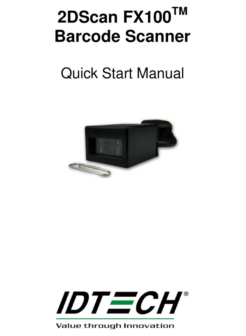
IDTECH 2DScan FX100 User manual

IDTECH

IDTECH 2DScan FX100 User manual

IDTECH Econoscan User manual

IDTECH

IDTECH Econoscan User manual

IDTECH 2DScan FX200 Instruction manual

IDTECH

IDTECH 2DScan FX200 Instruction manual

IDTECH BTScan User manual

IDTECH

IDTECH BTScan User manual

IDTECH Econoscan II Operating instructions

IDTECH

IDTECH Econoscan II Operating instructions

IDTECH 2DScan User manual

IDTECH

IDTECH 2DScan User manual

IDTECH 2DScan FX100 Instruction manual

IDTECH

IDTECH 2DScan FX100 Instruction manual

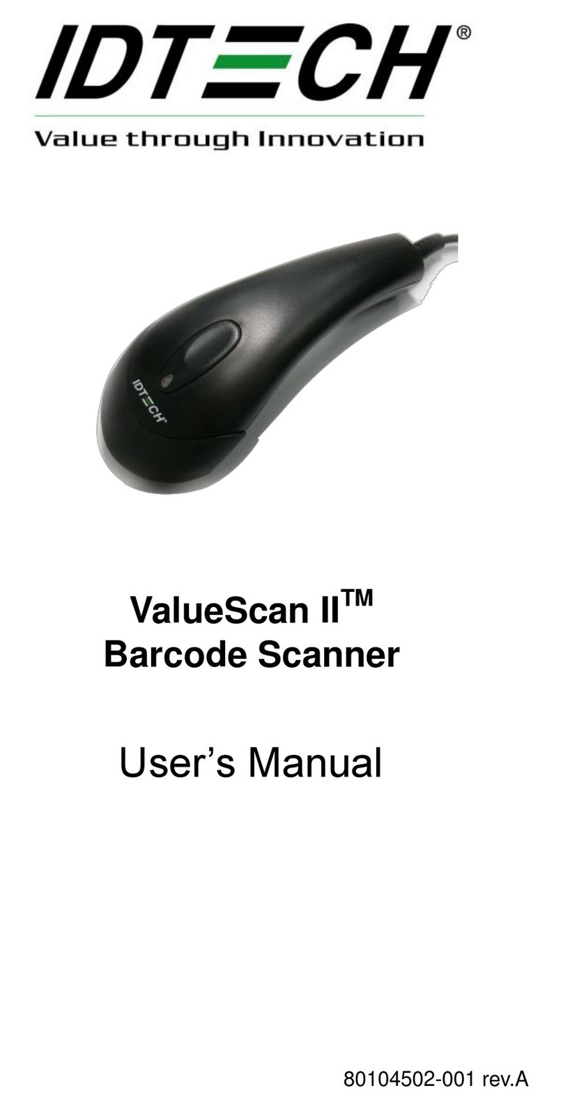
IDTECH ValueScan II User manual

IDTECH

IDTECH ValueScan II User manual

IDTECH 30 User manual

IDTECH

IDTECH 30 User manual

IDTECH ValueScan III IDBB-4244MRB User manual

IDTECH

IDTECH ValueScan III IDBB-4244MRB User manual

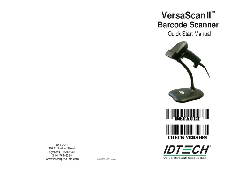
IDTECH VersaScan II User manual

IDTECH

IDTECH VersaScan II User manual

IDTECH MiniMag RS232 User manual

IDTECH

IDTECH MiniMag RS232 User manual

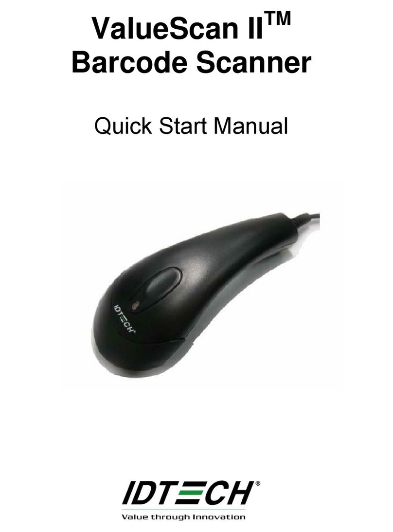
IDTECH ValueScan II Instruction manual

IDTECH

IDTECH ValueScan II Instruction manual

IDTECH VersaScan II Instruction manual

IDTECH

IDTECH VersaScan II Instruction manual

IDTECH Ez One Shot User manual

IDTECH

IDTECH Ez One Shot User manual

Popular Barcode Reader manuals by other brands

SATO ARGOX AS-9400DC user guide

SATO

SATO ARGOX AS-9400DC user guide

Unitech MS340BT user manual

Unitech

Unitech MS340BT user manual

Datalogic BC-80X0 Cradle Quick reference guide

Datalogic

Datalogic BC-80X0 Cradle Quick reference guide

Inateck BCST-33 user guide

Inateck

Inateck BCST-33 user guide

Cognex DataMan 70 Reference manual

Cognex

Cognex DataMan 70 Reference manual

Datalogic QuickScan QM2400 Quick reference guide

Datalogic

Datalogic QuickScan QM2400 Quick reference guide

Mindeo MD6000 user manual

Mindeo

Mindeo MD6000 user manual

Wireless 2877 user manual

Wireless

Wireless 2877 user manual

ChromaChecker CC-2D Quick user manual

ChromaChecker

ChromaChecker CC-2D Quick user manual

Cino Fuzzyscan quick start guide

Cino

Cino Fuzzyscan quick start guide

Tysso BCP-8000 user manual

Tysso

Tysso BCP-8000 user manual

Socket CHS 7Mi user guide

Socket

Socket CHS 7Mi user guide

Hand Held Products Quick Check 200 Series user guide

Hand Held Products

Hand Held Products Quick Check 200 Series user guide

Gryphon D100 user guide

Gryphon

Gryphon D100 user guide

Hand Held Products IMAGETEAM 4400 user guide

Hand Held Products

Hand Held Products IMAGETEAM 4400 user guide

Honeywell DCS19W Installation and user guide

Honeywell

Honeywell DCS19W Installation and user guide

Intermec SR61 quick start guide

Intermec

Intermec SR61 quick start guide

Microscan MS-820 user manual

Microscan

Microscan MS-820 user manual

manuals.online logo
manuals.online logoBrands
  • About & Mission
  • Contact us
  • Privacy Policy
  • Terms and Conditions

Copyright 2025 Manuals.Online. All Rights Reserved.